height SSANGYONG MUSSO 2003 User Guide
[x] Cancel search | Manufacturer: SSANGYONG, Model Year: 2003, Model line: MUSSO, Model: SSANGYONG MUSSO 2003Pages: 1574, PDF Size: 26.41 MB
Page 265 of 1574

M161 ENGINE MECHANICAL 1B2-113
Measurement of Mating Surface
1. Measure the height (H) of the cylinder head (refer to Service
data standard ).
2. Check the mating surface of the cylinder head.
3. Mill the sharp edge of the combustion chamber.
4. Re-measure the height (H) of the cylinder head.
5. Seal the intake and exhaust valves.
6. Measure the dimension (T) between the camshaft bearing and the valve system (refer to Service data standard).
7. Mill the cylinder head valve seat (refer to Service data
standard ).
Universal Tool Surface Grinding Machine
Sceledum, Type RTYRoaro
Schio/Italy
Page 269 of 1574

1B3-4 OM600 ENGINE MECHANICALSPECIAL TOOLS
SPECIAL TOOLS TABLE
603 589 00 09 00
Serration Wrench
657 589 03 63 00
Sliding Hammer 000 589 77 03 00
Box Wrench Insert
601 589 00 66 00 Counter Sink
667 589 00 23 00 Height Gauge 602 589 00 40 00
Engine Lock
116 589 20 33 00
Sliding Hammer 603 589 00 40 00
Counter Holder
Page 297 of 1574

1B3-32 OM600 ENGINE MECHANICAL
MILLING OF PRECHAMBER SEALING SURFACE1 Drift
2 Sleeve
3 Milling Cutter 4 Counter Sink (Special Tool - 601 589 00 66)
5 Cylinder Head
Tightening Torque 0.3, 0.6, 1.0 mm
Milling of the Prechamber Sealing Surface
Notice The prechamber sealing surface may only be remachined once with the cylinder head fitted. It is essential to adhere to the specified projection ‘C’ of the prechamber of 7.6 -
8.1mm. This ensures that the required clearance exists between prechamber and piston crown with the piston in TDC. Forthis reason, spacer rings should be inserted on remachinedsealing surfaces. If a spacer ring is already fitted, or a marking is made on the cylinder head, the cylinder head must be removed and size
‘C’ measured if further remachining is necessary on a
prechamber sealing surface.
Tools Required 601 589 00 66 00 Counter Sink 667 589 00 23 00 Height Gauge
Page 298 of 1574

OM600 ENGINE MECHANICAL 1B3-33
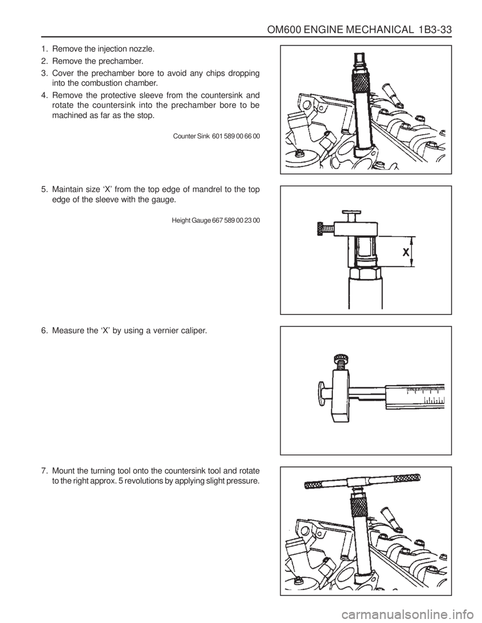
6. Measure the ‘X’ by using a vernier caliper.
7. Mount the turning tool onto the countersink tool and rotate to the right approx. 5 revolutions by applying slight pressure.
1. Remove the injection nozzle.
2. Remove the prechamber.
3. Cover the prechamber bore to avoid any chips droppinginto the combustion chamber.
4. Remove the protective sleeve from the countersink and rotate the countersink into the prechamber bore to be machined as far as the stop.
Counter Sink 601 589 00 66 00
5. Maintain size ‘X’ from the top edge of mandrel to the top
edge of the sleeve with the gauge.
Height Gauge 667 589 00 23 00
Page 387 of 1574

1B3-122 OM600 ENGINE MECHANICAL
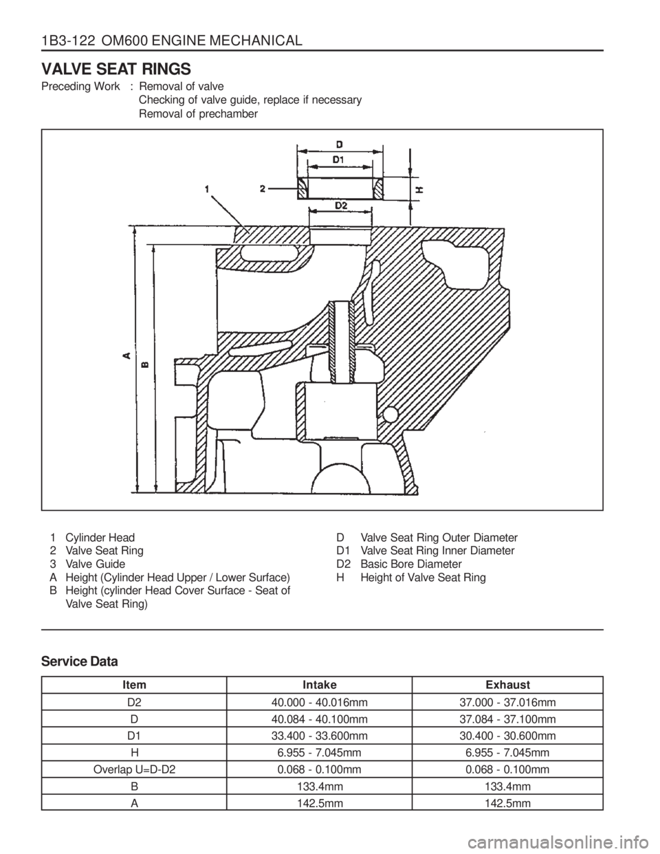
VALVE SEAT RINGS
Preceding Work : Removal of valveChecking of valve guide, replace if necessary
Removal of prechamber
1 Cylinder Head
2 Valve Seat Ring
3 Valve Guide
A Height (Cylinder Head Upper / Lower Surface)
B Height (cylinder Head Cover Surface - Seat of Valve Seat Ring) D Valve Seat Ring Outer Diameter
D1 Valve Seat Ring Inner Diameter
D2 Basic Bore Diameter
H Height of Valve Seat Ring
Service Data
Item D2D
D1 H
Overlap U=D-D2
B A Intake
40.000 - 40.016mm40.084 - 40.100mm33.400 - 33.600mm 6.955 - 7.045mm0.068 - 0.100mm
133.4mm142.5mm Exhaust
37.000 - 37.016mm37.084 - 37.100mm30.400 - 30.600mm 6.955 - 7.045mm0.068 - 0.100mm
133.4mm142.5mm
Page 393 of 1574

1B3-128 OM600 ENGINE MECHANICAL
Intake ValveExhaust Valve
Item
Valve Disc Diameter ‘d’
Valve Disc Height ‘h’
Setting Angle “� ” or Machining the Valve
Valve Stem Diameter ‘d1 ’
Valve Length ‘I’ Intake Valve
37.90 - 38.10 mm 1.7 mm45 °
7.955 - 7.970 mm
106.20 - 106.60 mm 105.30 - 105.70 0.03 mm Exhaust V
alve
34.90 - 35.10 mm 1.7 mm45 °
9.945 - 8.960 mm
106.20 - 106.60 mm 105.30 - 105.70 mm 0.03 mm
Standard Repair
Max. Permis Sible Runout at Valve Stem and Valve Seat
W = 38.0 ± 0.2mm
Matching ValvesCamshaft Cam Basic Dia.
Size (x)
Size (x) Size (x) 19.5 - 20.3mm
20.4 - 21.4mm
21.4 - 21.97mm W = 36.6 ± 0.2mm
Camshaft Cam Basic Dia.
19.5 - 20.1mm
20.2 - 21.2mm
21.2 - 21.97mm Valve to be Used
Use machined valve, if needed
new repair valve
I = 105.5 ± 0.2mm Reuse valve
Use standard size
valve
I = 106.4 ± 0.2mm
Page 394 of 1574

OM600 ENGINE MECHANICAL 1B3-129
Tools Required 001 589 32 21 00 Dial Gauge Checking and Machining
1. Clean the valves and do visual check.Valves with wobbled valve disc, with worn or scored valve stem should be replaced.
2. Measure valve disc height ‘h’.
Service data
Intake
Exhaust 1.7 ± 0.15 mm 1.7 ± 0.15 mm
3. Machine the valve. Notice Pay attention to setting angle ‘� ’ .
Commercial Tool
Valve corn grinding machine
4. Measure radial runout between valve stem and valve seat.
Limit Max. 0.03mm
Dial Gauge 001 589 32 21 00
Page 442 of 1574

1B3-178 OM600 ENGINE MECHANICALHeight ‘A’
(cylinder head surface - cylinder head cover surface) Minimum height after machiningPermissible unevenness of parting surface Permissible variation of parallelism (longitud. Direction) Peak-to-valley height
Valve arrears ‘a’
Prechamber protrusion
Service Data
In longitudinal direction In transverse direction Intake valve Exhaust valve
142.9 - 143.1mm
142.5mm0.08mm0.0mm
Max. 0.1mm
0.0017mm
0.1 - 0.7mm 0.1 - 0.7mm 7.6 - 8.1mm
FACING CYLINDER HEAD MATING SURFACE
Preceding Work : Removal of prechamber Cylinder head pressure leakage test
1 Valve
2 Cylinder Head
3 Prechamber
A Height of Cylinder Head B Longitudinal Direction
C Transverse Direction
a Valve Arrears
b Prechamber Protrusion
Page 443 of 1574

OM600 ENGINE MECHANICAL 1B3-179
Measurement Procedure
1. Measure height ‘A’ .
Limit 142.5 mm
Notice If the height is less than 142.5mm, replace the cylinder head.
2. Insert the valve (1) and measure valve arrears ‘a’.
Valve Arrears ‘a’ 0.1 - 0.7 mm
Notice If out of standard, machine the valve seat.
3. Install the prechamber and measure protrusion ‘C’.
Protrusion ‘C’ 7.6 - 8.1mm
4. Assemble the engine and check the valve timing.
Page 446 of 1574

1B3-182 OM600 ENGINE MECHANICAL Service Data
Height ‘Y’
Permissible unevenness of contacting surface Permissible roughness upper contacting surface Permissible variation of parallelism of crankcase uppersurface to lower surface in longitudinal directionPiston protrusion at TDC to crankcase upper surface
In longitudinal direction (B) In transverse direction (C) Min. 299.62 mm
0.06 mm 0.06 mm
0.0006 - 0.0016 mm 0.05 mm
0.965 mm0.735 mm
Max. Min.
FACING CRANKCASE CONTACTING SURFACE
1 Crankcase
2 Crankcase Contacting Surface
Y Height (crankcase upper surface - crankcase lower surface) B Longitudinal Direction
C Transverse Direction H Chamfer Heightb Chamfer Angle