SSANGYONG MUSSO 2003 User Guide
MUSSO 2003
SSANGYONG
SSANGYONG
https://www.carmanualsonline.info/img/67/57511/w960_57511-0.png
SSANGYONG MUSSO 2003 User Guide
Page 43 of 1574
M162 ENGINE MECHANICAL 1B1-7
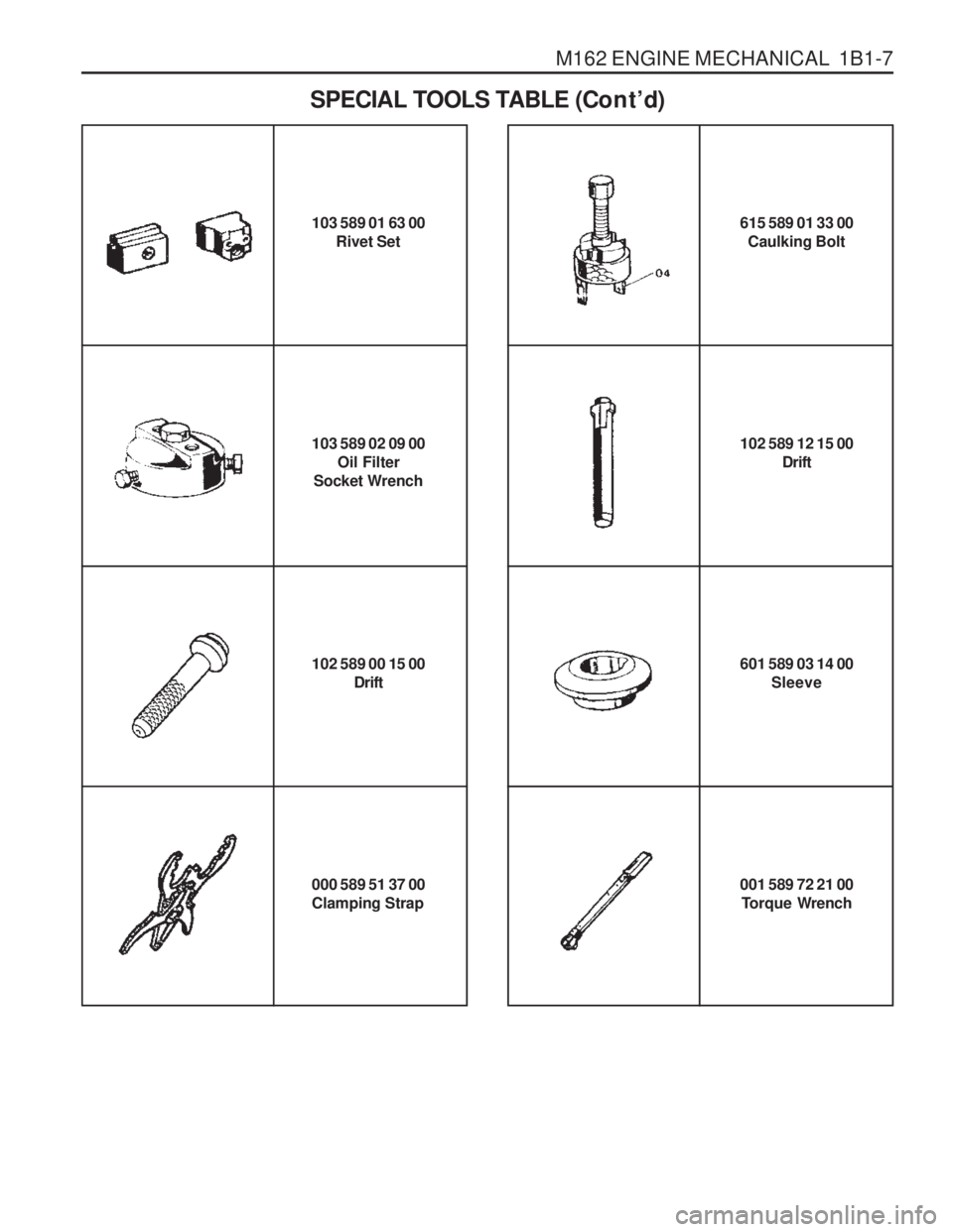
103 589 01 63 00Rivet Set
103 589 02 09 00 Oil Filter
Socket Wrench 102 589 12 15 00
Drift
SPECIAL TOOLS TABLE (Co n t
’d)
615 589 01 33 00
Caulking Bolt
102 589 00 15 00 Drift
000 589 51 37 00 Clamping Strap 001 589 72 21 00
Torque Wrench
601 589 03 14 00
Sleeve
Page 44 of 1574
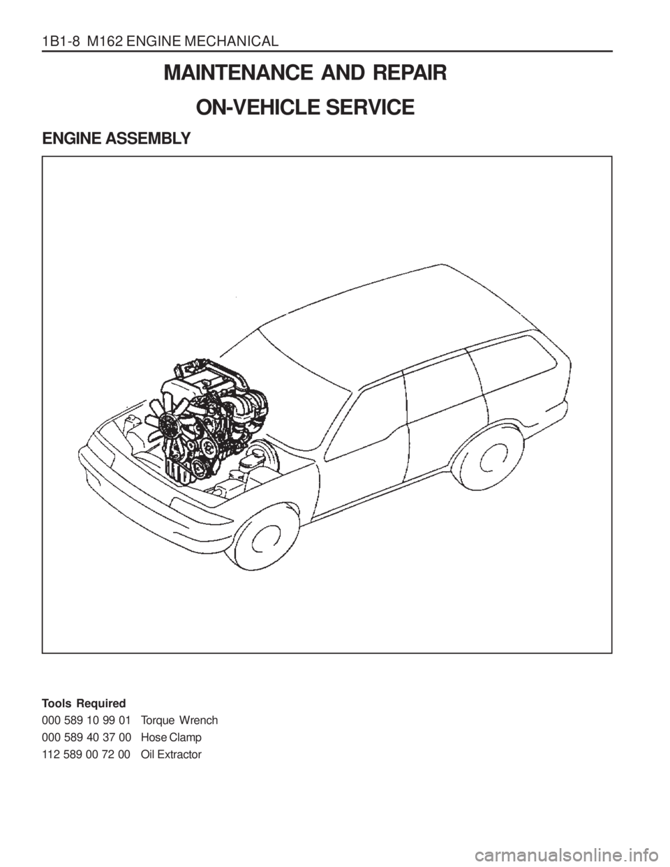
1B1-8 M162 ENGINE MECHANICALMAINTENANCE AND REPAIR
ON-VEHICLE SERVICE
ENGINE ASSEMBLY
Tools Required
000 589 10 99 01 Torque Wrench
000 589 40 37 00 Hose Clamp
112 589 00 72 00 Oil Extractor
Page 45 of 1574
M162 ENGINE MECHANICAL 1B1-9
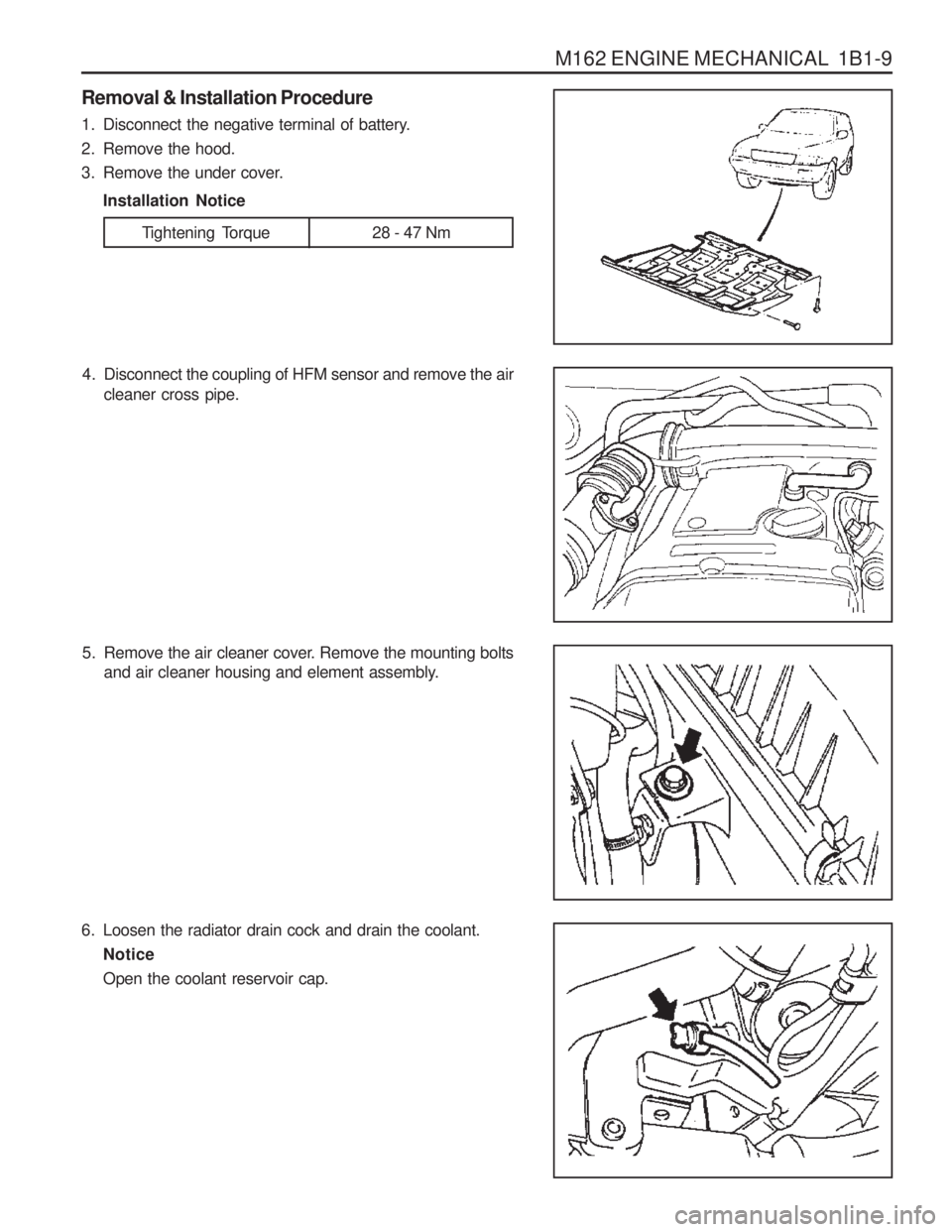
4. Disconnect the coupling of HFM sensor and remove the aircleaner cross pipe.
6. Loosen the radiator drain cock and drain the coolant. Notice Open the coolant reservoir cap.
5. Remove the air cleaner cover. Remove the mounting bolts
and air cleaner housing and element assembly.
Removal & Installation Procedure
1. Disconnect the negative terminal of battery.
2. Remove the hood.
3. Remove the under cover.
Installation Notice
Tightening Torque 28 - 47 Nm
Page 46 of 1574
1B1-10 M162 ENGINE MECHANICAL
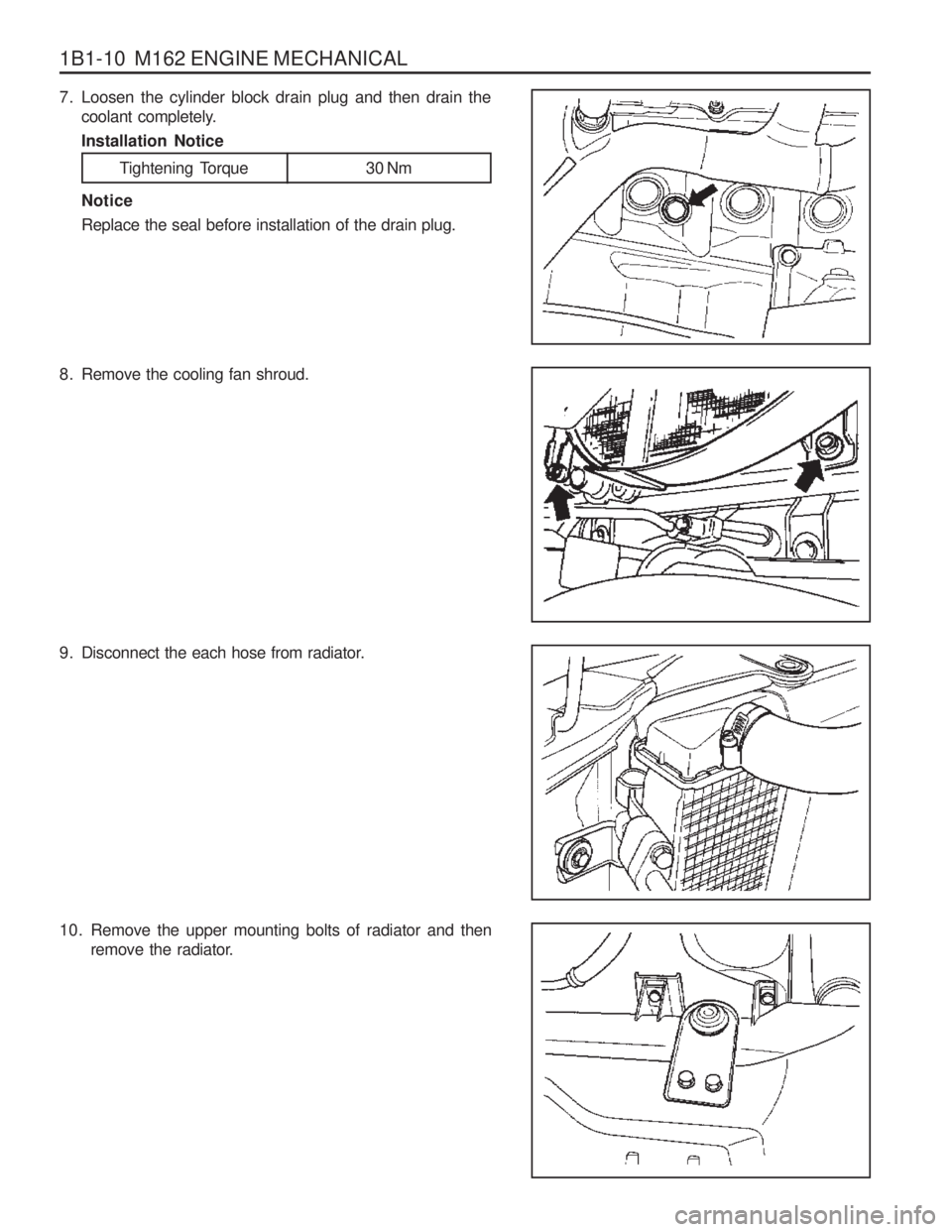
10. Remove the upper mounting bolts of radiator and thenremove the radiator.
7. Loosen the cylinder block drain plug and then drain thecoolant completely. Installation Notice
Tightening Torque 30 Nm
Notice Replace the seal before installation of the drain plug.
8. Remove the cooling fan shroud.
9. Disconnect the each hose from radiator.
Page 47 of 1574
M162 ENGINE MECHANICAL 1B1-11
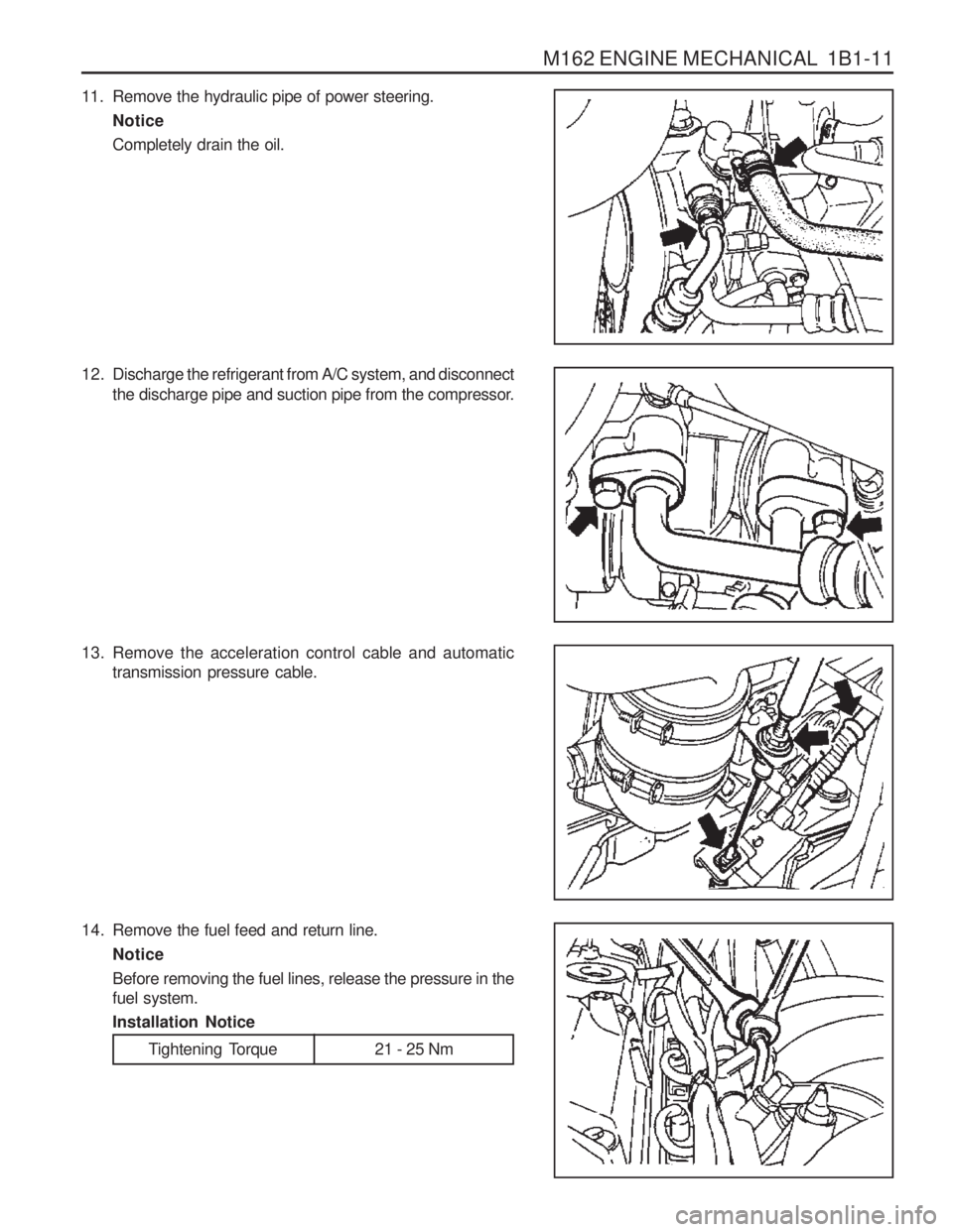
12. Discharge the refrigerant from A/C system, and disconnectthe discharge pipe and suction pipe from the compressor.
14. Remove the fuel feed and return line. Notice Before removing the fuel lines, release the pressure in the fuel system. Installation Notice
13. Remove the acceleration control cable and automatic
transmission pressure cable.
11. Remove the hydraulic pipe of power steering.
NoticeCompletely drain the oil.
Tightening Torque 21 - 25 Nm
Page 50 of 1574
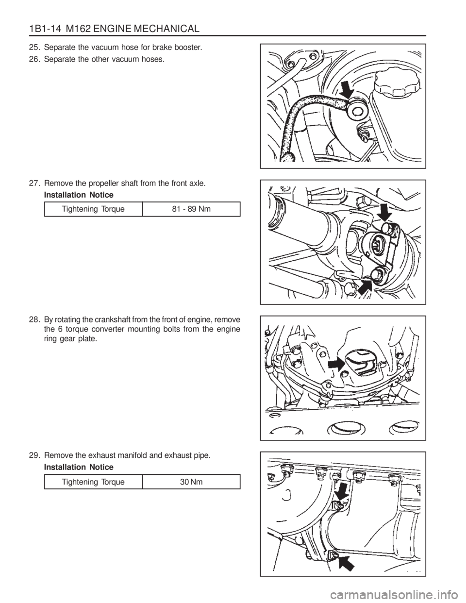
1B1-14 M162 ENGINE MECHANICAL
Tightening Torque 30 Nm
29. Remove the exhaust manifold and exhaust pipe.
Installation Notice
25. Separate the vacuum hose for brake booster.
26. Separate the other vacuum hoses.
27. Remove the propeller shaft from the front axle.Installation Notice
28. By rotating the crankshaft from the front of engine, remove the 6 torque converter mounting bolts from the engine ring gear plate.
Tightening Torque 81 - 89 Nm
Page 51 of 1574
M162 ENGINE MECHANICAL 1B1-15
30. Remove the transmission mounting bolts and separatethe transmission from the engine. Installation Notice
Tightening Torque 65 Nm
31. Remove the bolts for engine mounting bracket. Installation Notice
Tightening Torque 50 - 75 Nm
32. Hook the chain to the bracket of engine and by using a hoist or crane, carefully separate the engine assembly from the vehicle.
33. Installation should follow the removal procedure in the reverse order.
Page 54 of 1574
1B1-18 M162 ENGINE MECHANICAL
ALTERNATOR
1 Nut (M8)......................................... 22.5-27.5 Nm
2 Bolt (M8 x 30, 3 pieces) .................22.5-27.5 Nm
3 Bolt (M8 x 40, 1 piece) ...................22.5-27.5 Nm
Removal & Installation Procedure
1. Remove the drive belt.
2. Remove the alternator.
3. Unscrew the alternator carrier bolts and remove the carrier. Installation Notice 4 Bolt (M8 x 70, 1 piece)
...................22.5-27.5 Nm
5 Bolt (M8 x 75, 1 piece) ...................22.5-27.5 Nm
Tightening Torque 10 - 15 Nm
4. Installation should follow the removal procedure in the reverse order.
Page 56 of 1574
1B1-20 M162 ENGINE MECHANICAL Removal & Installation Procedure
1. Remove the belt pulley.Installation Notice
2. Disconnect the hydraulic pipe of the power steering pump and drain the oil.
3. Unscrew the bolts (arrows) and remove the steering pump. Installation Notice
Notice Pull the tensioning pulley clockwise as shown in the figure.
4. Remove the compressor after disconnecting the wiring connector and refrigerant pipe of A/C compressor. Notice Discharge all the refrigerant before removing the pipes.
Tightening Torque 40.5 - 49.5 Nm
Tightening Torque 22.5 - 27.5 Nm
Page 57 of 1574
M162 ENGINE MECHANICAL 1B1-21
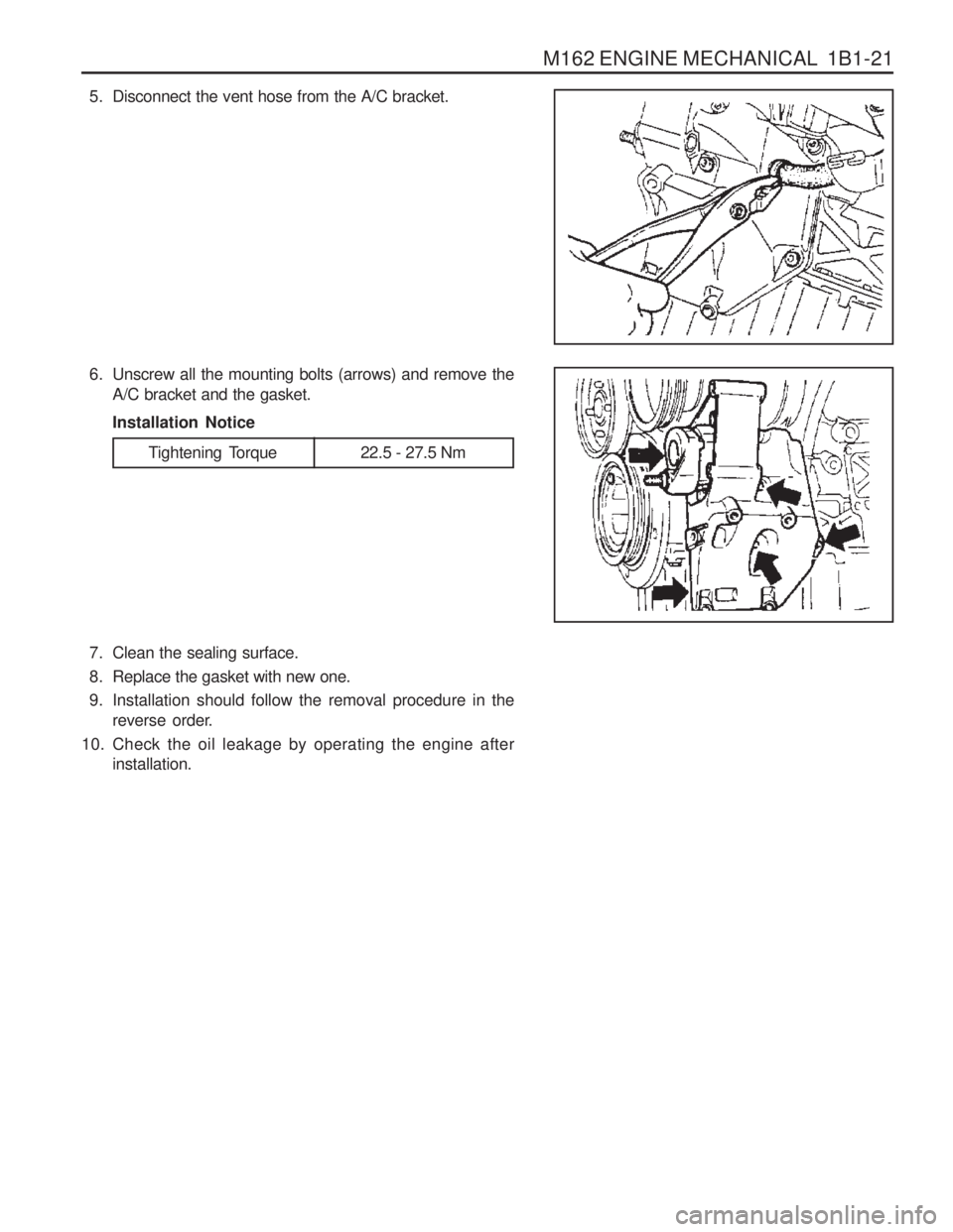
5. Disconnect the vent hose from the A/C bracket.
6. Unscrew all the mounting bolts (arrows) and remove theA/C bracket and the gasket. Installation Notice
7. Clean the sealing surface.
8. Replace the gasket with new one.
9. Installation should follow the removal procedure in the reverse order.
10. Check the oil leakage by operating the engine after installation.
Tightening Torque 22.5 - 27.5 Nm
