check oil SSANGYONG MUSSO 2003 Owner's Guide
[x] Cancel search | Manufacturer: SSANGYONG, Model Year: 2003, Model line: MUSSO, Model: SSANGYONG MUSSO 2003Pages: 1574, PDF Size: 26.41 MB
Page 229 of 1574
M161 ENGINE MECHANICAL 1B2-77
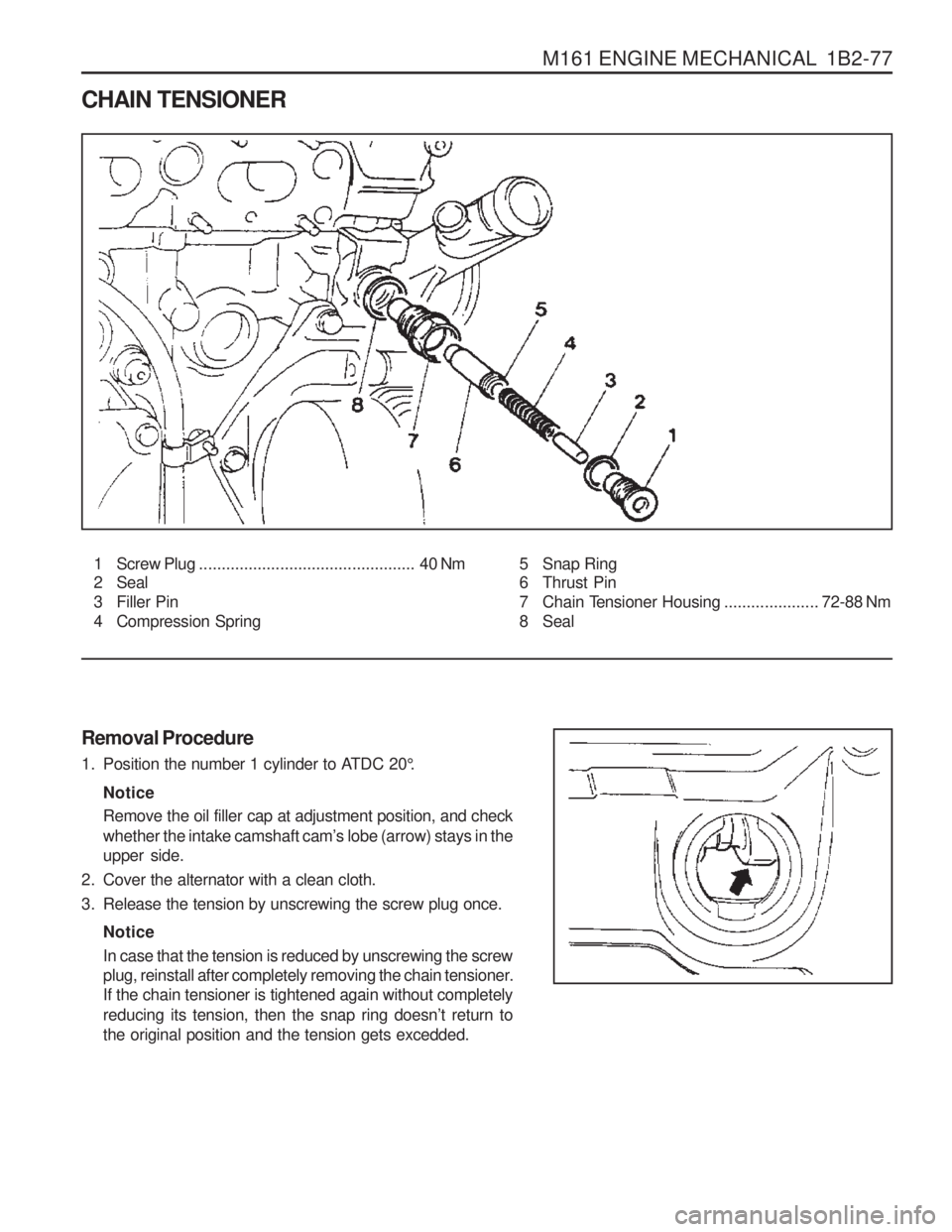
CHAIN TENSIONER1 Screw Plug ................................................ 40 Nm
2 Seal
3 Filler Pin
4 Compression Spring 5 Snap Ring
6 Thrust Pin
7 Chain Tensioner Housing
.....................72-88 Nm
8 Seal
Removal Procedure
1. Position the number 1 cylinder to A TDC 20°.
Notice Remove the oil filler cap at adjustment position, and check whether the intake camshaft cam ’s lobe (arrow) stays in the
upper side.
2. Cover the alternator with a clean cloth.
3. Release the tension by unscrewing the screw plug once.
NoticeIn case that the tension is reduced by unscrewing the screw
plug, reinstall after completely removing the chain tensioner.If the chain tensioner is tightened again without completely reducing its tension, then the snap ring doesn ’t return to
the original position and the tension gets excedded.
Page 231 of 1574
M161 ENGINE MECHANICAL 1B2-79
4. Lightly apply the grease to the seal (2) and install the screwplug (1). Installation Notice
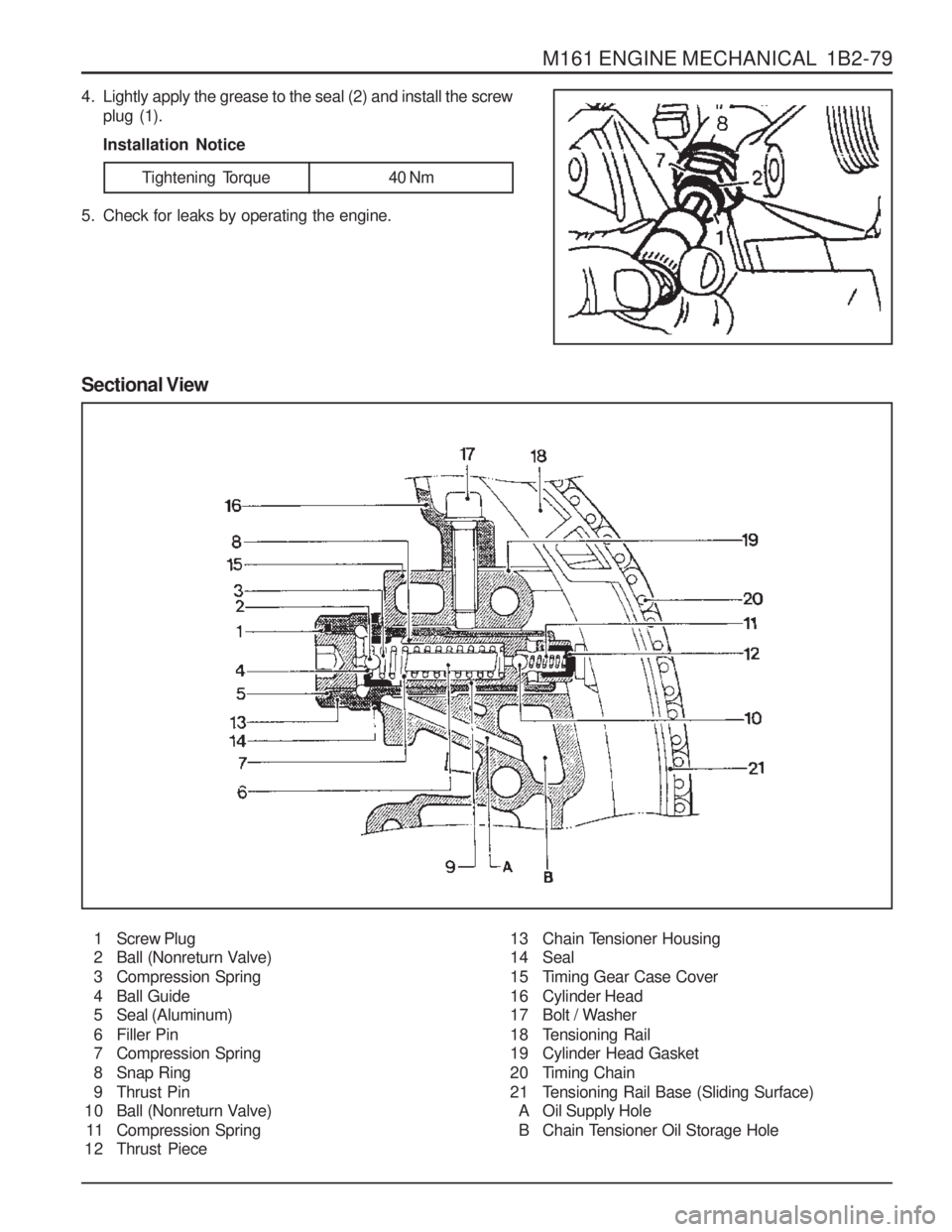
Sectional View
1 Screw Plug
2 Ball (Nonreturn Valve)
3 Compression Spring
4 Ball Guide
5 Seal (Aluminum)
6 Filler Pin
7 Compression Spring
8 Snap Ring
9 Thrust Pin
10 Ball (Nonreturn Valve)
11 Compression Spring
12 Thrust Piece 13 Chain Tensioner Housing
14 Seal
15 Timing Gear Case Cover
16 Cylinder Head
17 Bolt / Washer
18 Tensioning Rail
19 Cylinder Head Gasket
20 Timing Chain
21 Tensioning Rail Base (Sliding Surface)
A Oil Supply Hole
B Chain Tensioner Oil Storage Hole
5. Check for leaks by operating the engine.
Tightening Torque 40 Nm
Page 244 of 1574
1B2-92 M161 ENGINE MECHANICAL
1. Check the piston ring gap and apply the engine oil to thepiston pin and the connecting rod bushing.
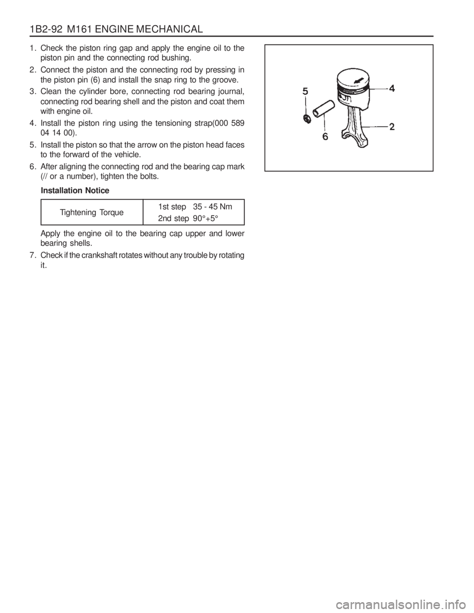
2. Connect the piston and the connecting rod by pressing in the piston pin (6) and install the snap ring to the groove.
3. Clean the cylinder bore, connecting rod bearing journal, connecting rod bearing shell and the piston and coat them with engine oil.
4. Install the piston ring using the tensioning strap(000 589 04 14 00).
5. Install the piston so that the arrow on the piston head faces to the forward of the vehicle.
6. After aligning the connecting rod and the bearing cap mark (// or a number), tighten the bolts.
Installation Notice
Tightening Torque 1st step 35 - 45 Nm
2nd step 90
°+5 °
Apply the engine oil to the bearing cap upper and lower bearing shells.
7. Check if the crankshaft rotates without any trouble by rotating it.
Page 249 of 1574
M161 ENGINE MECHANICAL 1B2-97
OIL PAN
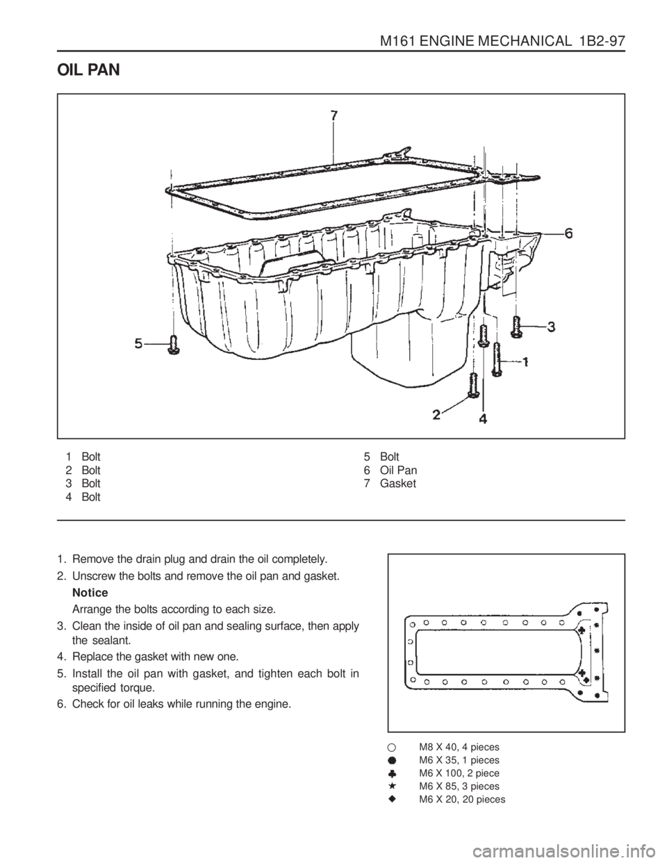
1 Bolt
2 Bolt
3 Bolt
4 Bolt
1. Remove the drain plug and drain the oil completely.
2. Unscrew the bolts and remove the oil pan and gasket. Notice Arrange the bolts according to each size.
3. Clean the inside of oil pan and sealing surface, then apply the sealant.
4. Replace the gasket with new one.
5. Install the oil pan with gasket, and tighten each bolt in specified torque.
6. Check for oil leaks while running the engine.
M8 X 40, 4 pieces M6 X 35, 1 piecesM6 X 100, 2 pieceM6 X 85, 3 piecesM6 X 20, 20 pieces5 Bolt
6 Oil Pan
7 Gasket
�
Page 252 of 1574
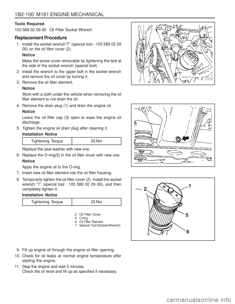
1B2-100 M161 ENGINE MECHANICAL9. Fill up engine oil through the engine oil filler opening.
10. Check for oil leaks at normal engine temperature after starting the engine.
11. Stop the engine and wait 5 minutes. Check the oil level and fill up as specified if necessary.
4. Remove the drain plug (1) and drain the engine oil.
Notice Leave the oil filler cap (3) open to ease the engine oil discharge.
5. Tighten the engine oil drain plug after cleaning it. Installation Notice
Tools Required
103 589 02 09 00 Oil Filter Socket Wrench Replacement Procedure
1. Install the socket wrench ”7” (special tool : 103 589 02 09
00) on the oil filter cover (2). NoticeMake the screw cover removable by tightening the bolt at the side of the socket wrench (special tool).
2. Install the wrench to the upper bolt in the socket wrench and remove the oil cover by turning it.
3. Remove the oil filter element.
Notice Work with a cloth under the vehicle when removing the oil filter element to not drain the oil. Replace the seal washer with new one.
6. Replace the O-ring(5) in the oil filter cover with new one.
Notice Apply the engine oil to the O-ring.
7. Insert new oil filter element into the oil filter housing.
Tightening Torque 25 Nm
8. Temporarily tighten the oil filter cover (2). Install the socket wrench “7” (special tool : 103 589 02 09 00), and then
completely tighten it. Installation Notice
2 Oil Filter Cover
5 O-ring
6 Oil Filter Element
7 Special Tool (Socket Wrench)
Tightening Torque 25 Nm
Page 257 of 1574
M161 ENGINE MECHANICAL 1B2-105
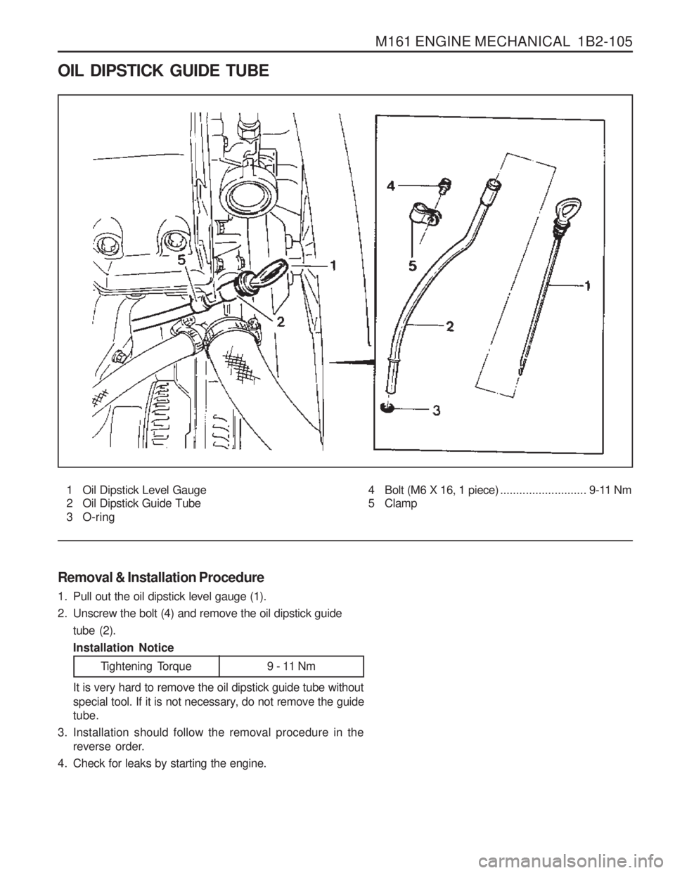
OIL DIPSTICK GUIDE TUBE
1 Oil Dipstick Level Gauge
2 Oil Dipstick Guide Tube
3 O-ring
Removal & Installation Procedure
1. Pull out the oil dipstick level gauge (1).
2. Unscrew the bolt (4) and remove the oil dipstick guide tube (2).Installation Notice 4 Bolt (M6 X 16, 1 piece)
........................... 9-11 Nm
5 Clamp
Tightening Torque 9 - 11 Nm
It is very hard to remove the oil dipstick guide tube without
special tool. If it is not necessary, do not remove the guide tube.
3. Installation should follow the removal procedure in the reverse order.
4. Check for leaks by starting the engine.
Page 266 of 1574
SECTION 1B3
OM600 ENGINE MECHANICAL
CAUTION: Disconnect the negative battery cable before removing or installing any electrical unit or when a tool or equipment could easily come in contact with exposed electrical terminals. Disconnecting this cable will help prevent personal injury and damage to the vehicle. The ignition must also be in LOCK unless otherwisenoted.
Specifications . . . . . . . . . . . . . . . . . . . . . . . 1B3-2Fastener Tightening Specifications . . . . . . . . 1B3-2
Special Tools . . . . . . . . . . . . . . . . . . . . . . . 1B3-4 Special Tools Table . . . . . . . . . . . . . . . . . . . . 1B3-4
Maintenance and Repair . . . . . . . . . . . . . 1B3-12
On-Vehicle Service . . . . . . . . . . . . . . . . . . . . 1B3-12
Engine Assembly . . . . . . . . . . . . . . . . . . . . 1B3-12
Poly V-Belt . . . . . . . . . . . . . . . . . . . . . . . . . 1B3-21
Tensioning Device . . . . . . . . . . . . . . . . . . . . 1B3-23
Poly V-Belt Alignment & Inspection . . . . . . . 1B3-26
Prechamber . . . . . . . . . . . . . . . . . . . . . . . . 1B3-29
Milling of Prechamber Sealing Surface . . . . 1B3-32
TDC (TDC Sensor Bracket) Setting . . . . . . 1B3-35
Cylinder Head . . . . . . . . . . . . . . . . . . . . . . . 1B3-37
Timing Case Cover . . . . . . . . . . . . . . . . . . . 1B3-63
Crankshaft End Cover . . . . . . . . . . . . . . . . 1B3-71
Vibration Damper and Hub . . . . . . . . . . . . . 1B3-74
Crankshaft Front Radial Seal . . . . . . . . . . . 1B3-80
Crankshaft Ball Bearing . . . . . . . . . . . . . . . 1B3-82
Crankshaft . . . . . . . . . . . . . . . . . . . . . . . . . 1B3-83
Flywheel . . . . . . . . . . . . . . . . . . . . . . . . . . . 1B3-93
Machining of Flywheel . . . . . . . . . . . . . . . . 1B3-97
Flywheel Ring Gear . . . . . . . . . . . . . . . . . . 1B3-98
Hydraulic Valve Clearance Compensation
Element Check . . . . . . . . . . . . . . . . . . . . 1B3-101
Valve Tappets . . . . . . . . . . . . . . . . . . . . . . 1B3-103
Valve Spring Check . . . . . . . . . . . . . . . . . 1B3-105
Valve Springs (Cylinder Head Removed) . 1B3-106
TABLE OF CONTENTS
Valve Springs (Cylinder Head Installed) . . 1B3-109
Valve Stem Seals . . . . . . . . . . . . . . . . . . . 1B3-112
Check and Replacement of Valve Guides . . . . . . . . . . . . . . . . . . . . . 1B3-116
Valve Seat Rings . . . . . . . . . . . . . . . . . . . 1B3-122
Check and Machining of Valves . . . . . . . . 1B3-127
Machining of Valve Seat . . . . . . . . . . . . . . 1B3-132
Camshaft Timing Test . . . . . . . . . . . . . . . . 1B3-137
Camshaft . . . . . . . . . . . . . . . . . . . . . . . . . 1B3-139
Chain Tensioner . . . . . . . . . . . . . . . . . . . . 1B3-145
Timing Chain . . . . . . . . . . . . . . . . . . . . . . . 1B3-147
Tensioning Rail . . . . . . . . . . . . . . . . . . . . . 1B3-151
Cylinder Head Guide Rail . . . . . . . . . . . . . 1B3-152
Timing Case Cover Guide Rail . . . . . . . . . 1B3-156
Crankshaft Sprocket . . . . . . . . . . . . . . . . . 1B3-158
Piston . . . . . . . . . . . . . . . . . . . . . . . . . . . . 1B3-163
Oil Filter . . . . . . . . . . . . . . . . . . . . . . . . . . 1B3-169
Oil Pan . . . . . . . . . . . . . . . . . . . . . . . . . . . 1B3-171
Oil Spray Nozzle . . . . . . . . . . . . . . . . . . . . 1B3-174
Oil Pump . . . . . . . . . . . . . . . . . . . . . . . . . . 1B3-175
Unit Repair . . . . . . . . . . . . . . . . . . . . . . . 1B3-177
Cylinder Head Pressure Leakage Test . . . 1B3-177
Facing Cylinder Head Mating Surface . . . . 1B3-178
Replacement of Crankcase Core Plug . . . 1B3-180
Facing Crankcase Contacting Surface . . . 1B3-182
Oil Gallery Steel Ball . . . . . . . . . . . . . . . . . 1B3-183
Cylinder Bore Measurement . . . . . . . . . . . 1B3-187
Page 335 of 1574
1B3-70 OM600 ENGINE MECHANICAL
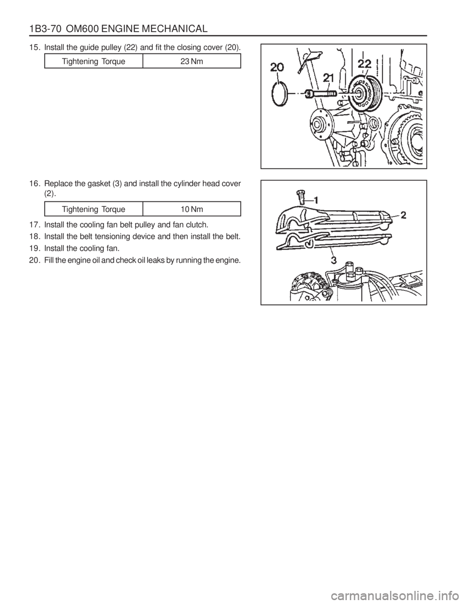
15. Install the guide pulley (22) and fit the closing cover (20).
16. Replace the gasket (3) and install the cylinder head cover(2).
17. Install the cooling fan belt pulley and fan clutch.
18. Install the belt tensioning device and then install the belt.
19. Install the cooling fan.
20. Fill the engine oil and check oil leaks by running the engine.
Tightening Torque 23 Nm
Tightening Torque 10 Nm
Page 356 of 1574
OM600 ENGINE MECHANICAL 1B3-91
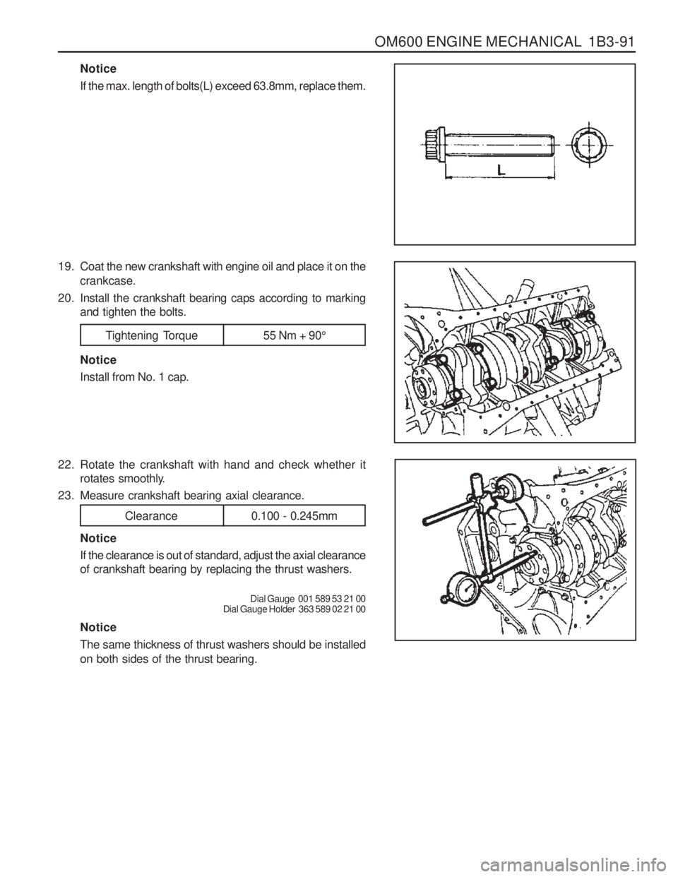
Notice If the max. length of bolts(L) exceed 63.8mm, replace them.
19. Coat the new crankshaft with engine oil and place it on the crankcase.
20. Install the crankshaft bearing caps according to marking and tighten the bolts.
Tightening Torque 55 Nm + 90 °
Notice Install from No. 1 cap.
22. Rotate the crankshaft with hand and check whether it rotates smoothly.
23. Measure crankshaft bearing axial clearance.
Clearance 0.100 - 0.245mm
Notice If the clearance is out of standard, adjust the axial clearance of crankshaft bearing by replacing the thrust washers.
Dial Gauge 001 589 53 21 00
Dial Gauge Holder 363 589 02 21 00
Notice The same thickness of thrust washers should be installed on both sides of the thrust bearing.
Page 357 of 1574
1B3-92 OM600 ENGINE MECHANICAL
28. Remove the connecting rod bearing cap.
29. Install the piston.
30. Rotate the crankshaft by hand and check whether it rotatessmoothly.
31. If the bearings are damaged,
- replace the oil presser relief valve. - clean the oil pump and oil filter housing carefully and
replace the hose if necessary. Notice After assembling the engine, check the camshaft timing, adjust the start of fuel injection and check the TDC sensorbracket setting.
32. Fill oil and run the engine and then check the oil pressure and oil level. Notice Install the original oil filter element and then change the engine oil and oil filter element after 1,000 - 1,500km.
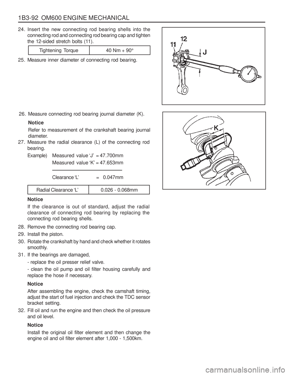
27. Measure the radial clearance (L) of the connecting rod
bearing. Example) Measured value ‘J’ = 47.700mm
Measured value ‘K’ = 47.653mm
Clearance ‘L’ = 0.047mm
Radial Clearance ‘L’0.026 - 0.068mm
Notice If the clearance is out of standard, adjust the radial clearance of connecting rod bearing by replacing theconnecting rod bearing shells.
26. Measure connecting rod bearing journal diameter (K).
Notice Refer to measurement of the crankshaft bearing journal
diameter.
24. Insert the new connecting rod bearing shells into theconnecting rod and connecting rod bearing cap and tighten
the 12-sided stretch bolts (11).
25. Measure inner diameter of connecting rod bearing.
Tightening Torque 40 Nm + 90 °