diagram SSANGYONG MUSSO 2003 Owner's Guide
[x] Cancel search | Manufacturer: SSANGYONG, Model Year: 2003, Model line: MUSSO, Model: SSANGYONG MUSSO 2003Pages: 1574, PDF Size: 26.41 MB
Page 1160 of 1574

7D-4 FATC-HAVC
CIRCUIT DIAGRAM
SCHEMATIC AND ROUTING DIAGRAMS
Page 1161 of 1574

FATC-HAVC 7D-5
FATC BLOCK DIAGRAM
INCAR SENSOR
AMBIENT SENSOR
WATER TEMPERATURE SENSOR
SUN LOAD SENSOR
TEMPERATURE SWITCH
BLOWER SWITCH
MODE SWITCH
DEFROSTER SWITCH
INTAKE SWITCH
AUTO SWITCH
A/CON SWITCH
OFF SWITCH
TEMP DOOR POSITION FEEDBACKVOLTAGE
POWER TRANSISTOR COLLECTORVOLTAGE
VFD
MAX HI RELAY
POWER T/R
BLOWERMOTOR
ECUCOMPRESSOR
MIX ACTUATORMIX DOOR
INTAKE ACTUATORINTAKE DOOR
MODE ACTUATORMODE DOOR
Airconditioner output
C ON
T
RO L
UN I
T
Page 1181 of 1574

SECTION 8B
SUPPLEMENTAL RESTRAINT SYSTEM(SRS)
Specifications . . . . . . . . . . . . . . . . . . . . . . . . 8B-1General Specifications . . . . . . . . . . . . . . . . . . 8B-1
Schematic and Routing Diagrams . . . . . . . . 8B-2 Air Bag . . . . . . . . . . . . . . . . . . . . . . . . . . . . . . 8B-2
Cautions . . . . . . . . . . . . . . . . . . . . . . . . . . . . 8B-3
Function Description . . . . . . . . . . . . . . . . . . 8B-4 Air Bag Module . . . . . . . . . . . . . . . . . . . . . . . . 8B-6
Diagnosis . . . . . . . . . . . . . . . . . . . . . . . . . . . 8B-7 Description . . . . . . . . . . . . . . . . . . . . . . . . . . . 8B-7
Self Diagnosis . . . . . . . . . . . . . . . . . . . . . . . . 8B-10
Circuit Diagram . . . . . . . . . . . . . . . . . . . . . . . 8B-16
TABLE OF CONTENTS
Caution: Disconnect the negative battery cable before removing or installing any electrical unit or when a tool or equipment could easily come in contact with exposed electrical terminals. Disconnecting this cable will help prevent personal injury and damage to the vehicle. The ignition must also be in LOCK unless otherwisenoted.
SPECIFICATIONS
GENERAL SPECIFICATIONS
Application
Air bag System Deployment Time
Detection Time
Operating Temperature
Storage TemperatureAir Bag Replacement Interval
Voltage Range Current Consumption Acceleration Range Max. Acceleration
Voltage Ramp Energy Reservation Inflator Ignition EnergySquib Resistance
Air Bag Warning Lamp ON Time (When Ignition ON) Description
< 20ms< 5ms
-40°C ~ +85°C
-40°C ~ +90°C
Every 10-year after installation 9-16V
5ms after ignition switch ON < 1A,
5ms ~ 5sec. <300mA, after 5sec. < 100mA
+/-50g
+/-600g pulse 0.5 ~ 2.0 V/s
150ms after battery disconnection
4.3mJ
2.15 ± 0.35 �
6 sec.Air Bag Diagram . . . . . . . . . . . . . . . . . . . . . . 8B-17
Maintenance and Repair . . . . . . . . . . . . . . 8B-18
On-Vehicle Service . . . . . . . . . . . . . . . . . . . . . 8B-18
Air Bag Module . . . . . . . . . . . . . . . . . . . . . . . 8B-18
Clock Spring . . . . . . . . . . . . . . . . . . . . . . . . . 8B-19
Air Bag Control Unit (AC4) . . . . . . . . . . . . . . 8B-21
General Description and System Operation . . . . . . . . . . . . . . . . . . . . . . . . 8B-22
Introduction . . . . . . . . . . . . . . . . . . . . . . . . . . 8B-22
Caution . . . . . . . . . . . . . . . . . . . . . . . . . . . . . 8B-22
Page 1182 of 1574

8B-2 SUPPLEMENTAL RESTRAINT SYSTEM(SRS)SCHEMATIC AND ROUTING DIAGRAMS
AIR BAG
Page 1196 of 1574

8B-16 SUPPLEMENTAL RESTRAINT SYSTEM(SRS) CIRCUIT DIAGRAM
Page 1197 of 1574

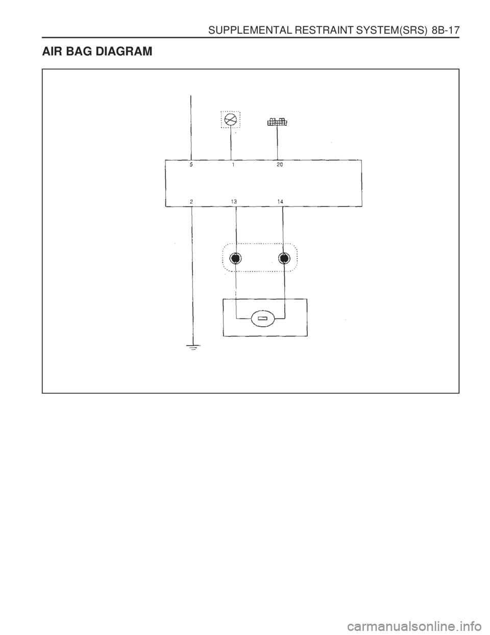
SUPPLEMENTAL RESTRAINT SYSTEM(SRS) 8B-17
AIR BAG DIAGRAM
Page 1203 of 1574

SECTION 9A
BODY WIRING SYSTEM
Schematic and Routing Diagrams . . . . . . . . 9A-2
Power Distribution . . . . . . . . . . . . . . . . . . . . . . 9A-2
Starting & Charging (Gasoline HFM) . . . . . . . 9A-3
Starting & Charging (Diesel) . . . . . . . . . . . . . . 9A-4
Fuse Box and Relay . . . . . . . . . . . . . . . . . . . 9A-5
Location of Connectors by
Wiring Harness . . . . . . . . . . . . . . . . . . . . . 9A-7
Main . . . . . . . . . . . . . . . . . . . . . . . . . . . . . . . . 9A-7
Engine Room . . . . . . . . . . . . . . . . . . . . . . . . 9A-11
Floor . . . . . . . . . . . . . . . . . . . . . . . . . . . . . . . 9A-13
Roof . . . . . . . . . . . . . . . . . . . . . . . . . . . . . . . 9A-14
Driver's Door . . . . . . . . . . . . . . . . . . . . . . . . . 9A-15
Passenger's Door . . . . . . . . . . . . . . . . . . . . . 9A-15
TABLE OF CONTENTS
Caution: Disconnect the negative battery cable before removing or installing any electrical unit or when a tool or equipment could easily come in contact with exposed electrical terminals. Disconnecting this cable will help prevent personal injury and damage to the vehicle. The ignition must also be in LOCK unless otherwisenoted.
Rear Left Door . . . . . . . . . . . . . . . . . . . . . . . 9A-16
Rear Right Door . . . . . . . . . . . . . . . . . . . . . . 9A-16
Tail Gate . . . . . . . . . . . . . . . . . . . . . . . . . . . . 9A-17
Semi Automatic Air Conditioner . . . . . . . . . . 9A-18
Full automatic Air Conditioner . . . . . . . . . . . . 9A-19
Gasoline Engine (MSE) . . . . . . . . . . . . . . . . 9A-20
Gasoline Engine (HFM) . . . . . . . . . . . . . . . . 9A-21
Diesel Engine . . . . . . . . . . . . . . . . . . . . . . . . 9A-22
Manual Transmission . . . . . . . . . . . . . . . . . . 9A-23
Automatic Transmission (BENZ) . . . . . . . . . . 9A-24
Automatic Transmission (BTRA) . . . . . . . . . . 9A-25
Driver's Seat . . . . . . . . . . . . . . . . . . . . . . . . . 9A-26
Page 1204 of 1574

9A-2 BODY WIRING SYSTEMSCHEMATIC AND ROUTING DIAGRAMS
POWER DISTRIBUTION
Page 1229 of 1574

Low (Philips H4)Tail Lamp
Brake Lamp
High Mounted Stop Lamp Reverse LampFog Lamp*
Turn Signal Lamp Position Lamp
Front LampRear Lamp
Luggage Lamp
Door Courtesy Lamp SECTION 9B
LIGHTING SYSTEM
Caution: Disconnect the negative battery cable before removing or installing any electrical unit or when a tool or equipment could easily come in contact with exposed electrical terminals. Disconnecting this cable will help prevent personal injury and damage to the vehicle. The ignition must also be in LOCK unless otherwisenoted.
TABLE OF CONTENTS
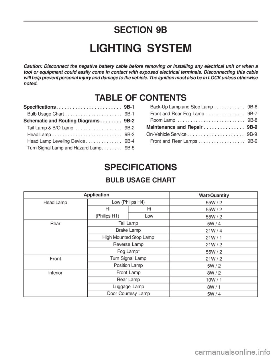
SPECIFICATIONSBULB USAGE CHART
Head Lamp Rear
Front
Interior
Application
Specifications . . . . . . . . . . . . . . . . . . . . . . . . 9B-1
Bulb Usage Chart . . . . . . . . . . . . . . . . . . . . . . 9B-1
Schematic and Routing Diagrams . . . . . . . . 9B-2 Tail Lamp & B/O Lamp . . . . . . . . . . . . . . . . . . 9B-2
Head Lamp . . . . . . . . . . . . . . . . . . . . . . . . . . . 9B-3
Head Lamp Leveling Device . . . . . . . . . . . . . . 9B-4
Turn Signal Lamp and Hazard Lamp . . . . . . . . 9B-5 Back-Up Lamp and Stop Lamp . . . . . . . . . . . .
9B-6
Front and Rear Fog Lamp . . . . . . . . . . . . . . . 9B-7
Room Lamp . . . . . . . . . . . . . . . . . . . . . . . . . . 9B-8
Maintenance and Repair . . . . . . . . . . . . . . . 9B-9
On-Vehicle Service . . . . . . . . . . . . . . . . . . . . . 9B-9 Front and Rear Lamps . . . . . . . . . . . . . . . . . . 9B-9
Hi
(Philips H1)
Hi
Low Watt/Quantity
55W / 2 55W / 2 55W / 25W / 4
21W / 4 21W / 121W / 2 55W / 2 21W / 2 5W / 28W / 2
10W / 1
8W / 15W / 4
Page 1230 of 1574

9B-2 LIGHTING SYSTEM
TAIL LAMP & B/O LAMP
SCHEMATIC AND ROUTING DIAGRAMS
15
(NO.15)
OVPR