SSANGYONG NEW ACTYON SPORTS 2012 Service Manual
NEW ACTYON SPORTS 2012
SSANGYONG
SSANGYONG
https://www.carmanualsonline.info/img/67/57513/w960_57513-0.png
SSANGYONG NEW ACTYON SPORTS 2012 Service Manual
Trending: power steering, jacking points, radiator, immobilizer, refrigerant type, lock, catalytic converter
Page 411 of 828
01-6
2) Interior Fuse and Relay Box on Passenger Side
Page 412 of 828
01-78410-02
5. OPERATING PROCESS OF ICM BOX
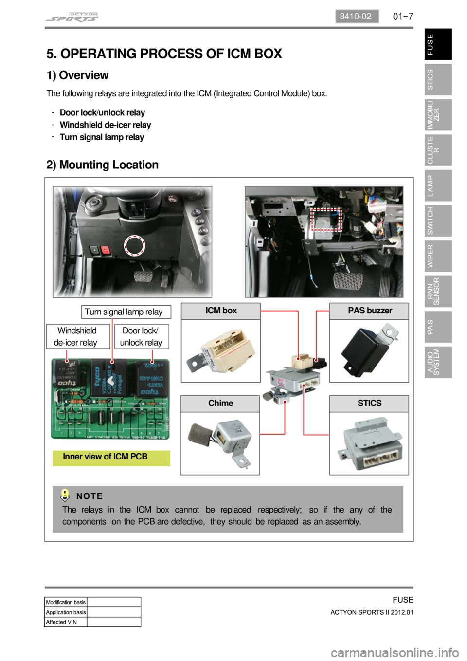
The following relays are integrated into the ICM (Integrated Control Module) box.
Door lock/unlock relay
Windshield de-icer relay
Turn signal lamp relay -
-
-
1) Overview
2) Mounting Location
Door lock/
unlock relay
Turn signal lamp relay
Windshield
de-icer relay
Inner view of ICM PCB
PAS buzzer
Chime
ICM box
STICS
The relays in the ICM box cannot be replaced respectively; so if the any of the
components on the PCB are defective, they should be replaced as an assembly.
Page 413 of 828
01-8
3) Operating Process by Power Supply of ICM Box
(1) Door lock relay
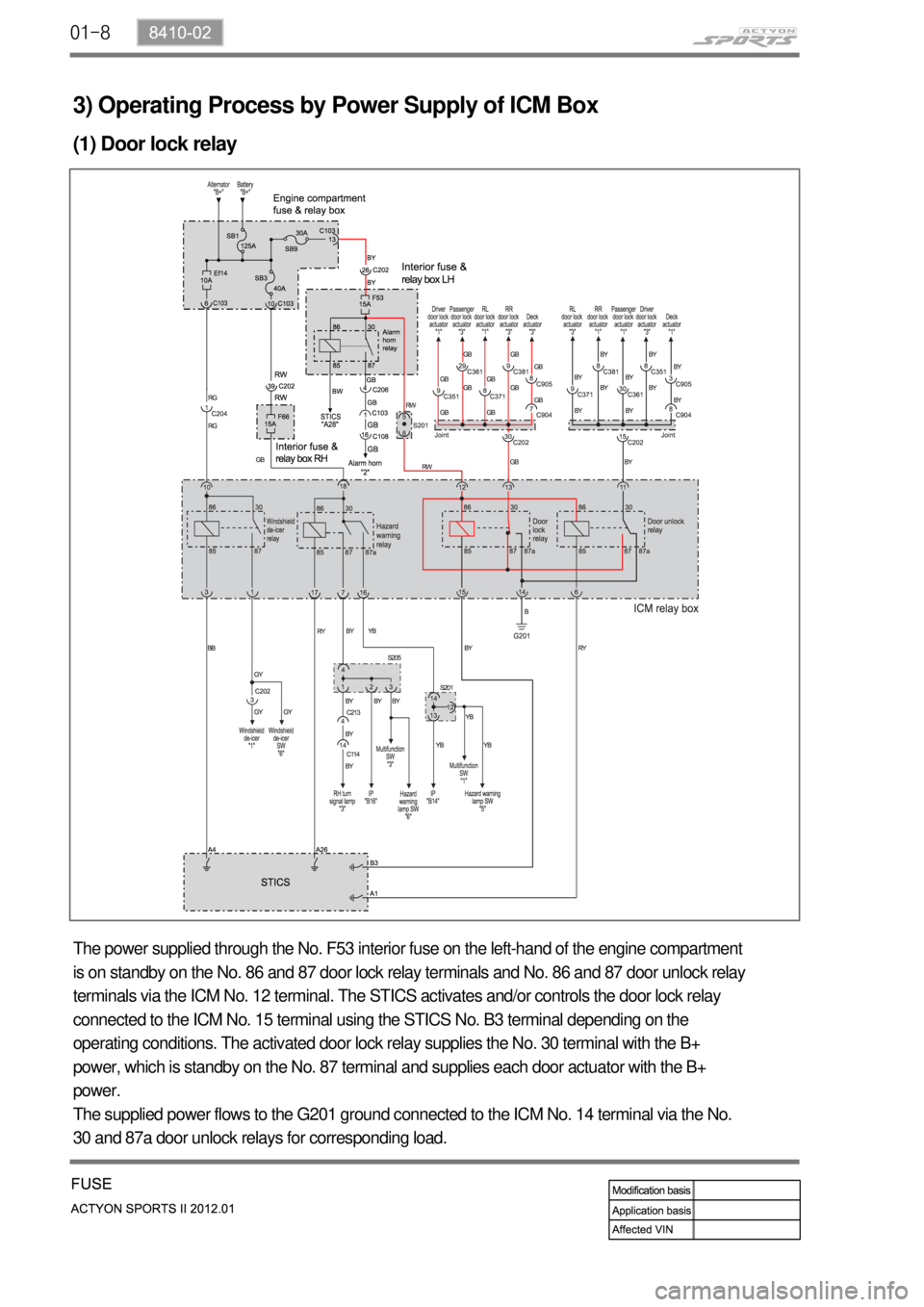
The power supplied through the No. F53 interior fuse on the left-hand of the engine compartment
is on standby on the No. 86 and 87 door lock relay terminals and No. 86 and 87 door unlock relay
terminals via the ICM No. 12 terminal. The STICS activates and/or controls the door lock relay
connected to the ICM No. 15 terminal using the STICS No. B3 terminal depending on the
operating conditions. The activated door lock relay supplies the No. 30 terminal with the B+
power, which is standby on the No. 87 terminal and supplies each door actuator with the B+
power.
The supplied power flows to the G201 ground connected to the ICM No. 14 terminal via the No.
30 and 87a door unlock relays for corresponding load.
Page 414 of 828
01-98410-02
(2) Door unlock relay
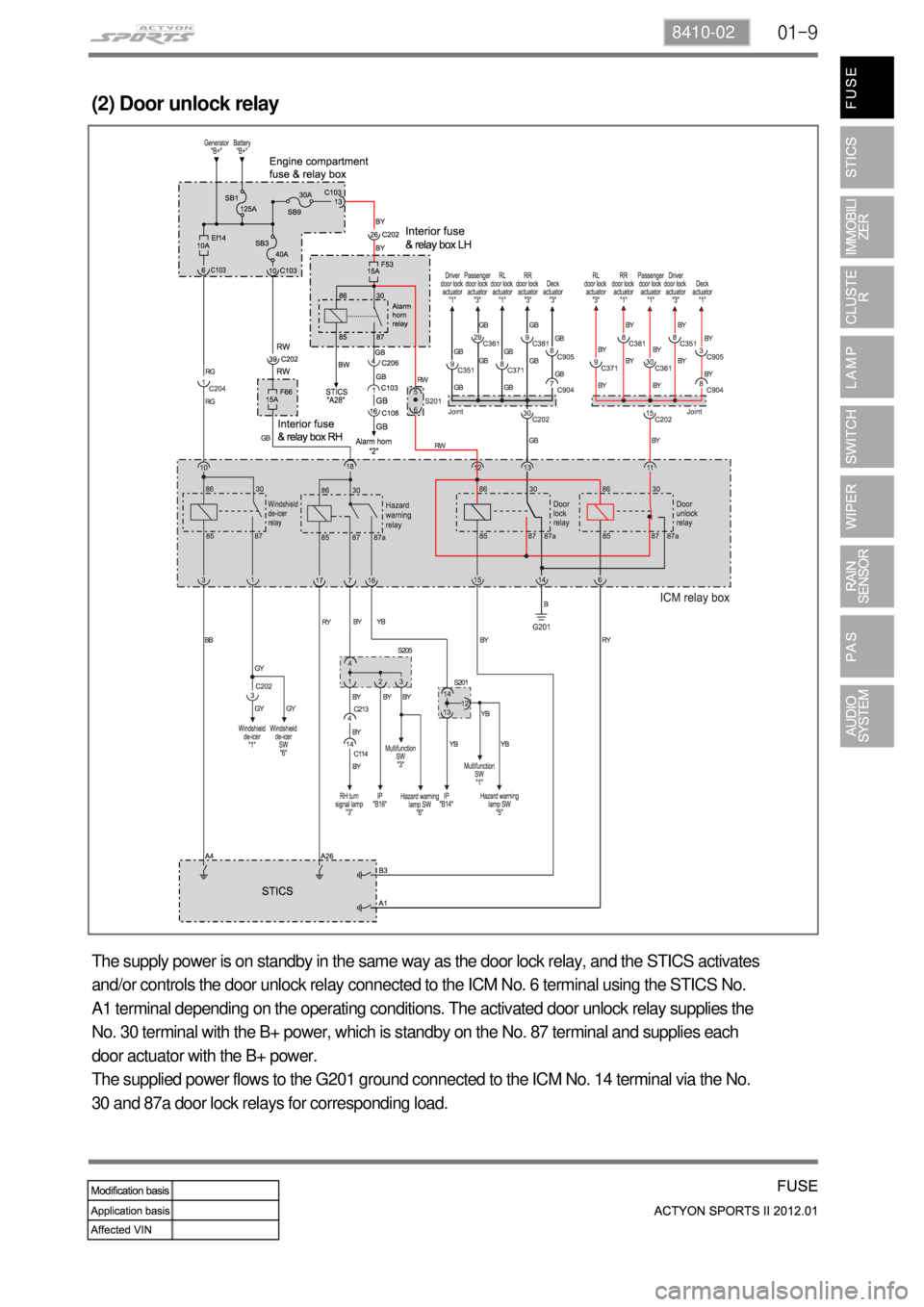
The supply power is on standby in the same way as the door lock relay, and the STICS activates
and/or controls the door unlock relay connected to the ICM No. 6 terminal using the STICS No.
A1 terminal depending on the operating conditions. The activated door unlock relay supplies the
No. 30 terminal with the B+ power, which is standby on the No. 87 terminal and supplies each
door actuator with the B+ power.
The supplied power flows to the G201 ground connected to the ICM No. 14 terminal via the No.
30 and 87a door lock relays for corresponding load.
Page 415 of 828
01-10
(3) Turn signal lamp (Hazard warning lamp operation)
The B+ power supplied through the No. F66 interior fuse on the right-hand of the engine
compartment is on standby on the No. 30 and 86 hazard warning lamp relay terminals via the ICM
No. 18 terminal.
The STICS activates and/or controls the hazard warning lamp relay using the No. A26 terminal
depending on the operating conditions. The activated relay supplies the No. 87 and 87a terminals
with the power, which is on standby on the No. 30 hazard warning lamp relay terminal.
The supplied power flows to the corresponding circuit via the No. 7 and 16 ICM terminals.
Page 416 of 828
01-118410-02
(4) Windshield de-icer operation
The B+ power supplied through the No. Ef14 fuse and relay box in the engine compartment is on
standby on the No. 30 and 86 windshield de-icer relay terminals via the ICM No. 10 terminal.
The STICS activates and/or controls the windshield de-icer relay using the No. A4 terminal
depending on the operating conditions. The activated relay supplies the No. 87 terminal with the
power, which is on standby on the No. 30 windshield de-icer lamp relay terminal.
The supplied power flows to the windshield de-icer circuit via the No. 1 ICM terminal.
Page 417 of 828

02-38710-01
1. PERFORMANCE AND SPECIFICATIONS
1) Rated Load & Input Signals
Rated Load ▶
NO. Item Rated Load
1 Chime bell / Buzzer DC 12V 350 mA (Inductive load)
2 Front room lamp DC 12V 16W (Lamp load)
3 Rear room lamp DC 12V 8W (Lamp load)
4 Ignition key illumination DC 12V 1.2W (Lamp load)
5 Seat belt indicator DC 12V 1.2W (Lamp load)
6 Parking brake warning lamp DC 12V 1.2W (Lamp load)
7 Door ajar warning lamp DC 12V 1.2W (Lamp load)
8 Door lock relay DC 12V 200 mA (Inductive load)
9 Door unlock relay DC 12V 200 mA (Inductive load)
10 Horn relay DC 12V 260 mA
11 Tail lamp relay DC 12V 200 mA (Inductive load)
12 Hazard warning lamp relay DC 12V 200 mA (Inductive load)
13 Power window relay DC 12V 200 mA (Inductive load)
14 Rear defogger relay DC 12V 200 mA (Inductive load)
15 Wiper LOW relay DC 12V 200 mA (Inductive load)
16 Wiper HIGH relay DC 12V 200 mA (Inductive load)
17 Front washer motor DC 12V 1.5A
18 Head lamp relay DC 12V 750 mA (Inductive load)
19 Front defogger relay DC 12V 200 mA (Inductive load)
20 Mirror lock relay DC 12V 200 mA (Inductive load)
21 Mirror unlock relay DC 12V 200 mA (Inductive load)
Page 418 of 828

02-4
Input Signals ▶
NO. Input Signal Name Logic Status
1 IGN1 ON = BAT
(IGN ON or START)
2 IGN2 ON = BAT (IGN ON)
3 ALT_D ON = BAT (engine started)
4 Key reminder switch IN = BAT (key in)
5 Driver's door switch OPEN = GND, CLOSE = OPEN
6 Passenger's door switch OPEN = GND, CLOSE = OPEN
7 Rear door switch - OPEN (one of rear doors) = GND
- CLOSE (all rear doors) = OPEN
8 Hood switch OPEN = GND, CLOSE = OPEN
9 Driver's door lock/unlock switch LOCK = OPEN, UNLOCK = GND
10 Passenger's door lock/unlock switch LOCK = OPEN, UNLOCK = GND
11 Rear door lock/unlock switch - UNLOCK (one of rear doors)
= GND
- LOCK (all rear doors) = OPEN
12 Tailgate lock/unlock switch LOCK = OPEN, UNLOCK = GND
13 Rear defogger switch ON = GND, OFF = OPEN
14 Seat belt switch Unfastened = GND, Fastened = OPEN
15 Sunroof open switch ON = GND, OFF = OPEN
16 Parking brake switch ON = GND, OFF = OPEN
17 Air bag collision sensor ON = 200 ms output (LOW), OFF = OPEN
18 Wiper motor (parking) switch STOP = BAT VOLTAGE, ROTATING = GND
19 Washer switch ON = BAT, OFF = OPEN
20 INT-AUTO switch ON = BAT, OFF = OPEN
21 Auto washer switch ON = BAT, OFF = OPEN
22 Intermittent resistance 0W ~ 51KW (for intermittent wiper)
23 Speed sensor ON = GND (PWM), OFF = OPEN
24 Mirror lock/unlock switch ON = GND, OFF = OPEN
25 Front defogger switch ON = GND, OFF = OPEN
26 Auto hazard switch ON = GND, OFF = OPEN
Page 419 of 828
02-58710-01
NO. Input Signal Name Logic Status
27 Central door lock switch ON = GND, OFF = OPEN
28 Multifunction auto light switch ON = GND, OFF = OPEN
29 Turn signal lamp switch ON = BAT/GND, OFF = OPEN
(approx. 5.1 V ~ 9.2 V)
30 Rain sensor ON = GND (DATA), OFF = BAT
31 Telematics ON = GND (DATA), OFF = BAT
32 Diagnosis ON = GND (DATA), OFF = BAT (KWP2000)
Page 420 of 828
02-6
1. GENERAL
STICS of KORANDO SPORTS, called as RKSTICS (REKES + STICS (Super Time & Integrated
Control System)), is almost the same as that of ACTYON SPORTS in terms of its function and
role.
Chime
STICS unit
PAS buzzerICM relay box
Inside of Lower IP Cover on Drive
Side
Trending: sensor, air suspension, battery capacity, wiring, oil reset, width, refrigerant type


