SSANGYONG RODIUS 2005 Service Manual
RODIUS 2005
SSANGYONG
SSANGYONG
https://www.carmanualsonline.info/img/67/57522/w960_57522-0.png
SSANGYONG RODIUS 2005 Service Manual
Trending: trunk, transmission oil, brake pads, torque, battery replacement, fuses, heater
Page 201 of 502
0-4
RODIUS 2005.07
3170-01
MANUAL TRANSMISSION
1. MANUAL TRANSMISSION OVERVIEW
4WD
2WD
TSM54/52 transmission is designed to link the gear ratio, installation dimensions and shapes
with current T5 transmission and BTRA automatic transmission. It provides maximum
drivability by the optimized engine torque and gear ratio.
TSM54/52 transmission uses linkage type shift elements directly connected to the
transmission. It prevent the transmission from shifting to the reverse gear from 5th gea
r
when shifting to reverse gear. It also prevents the break and wear. 1.
2.
Page 202 of 502
0-5
MANUAL TRANSMISSION
RODIUS 2005.07
3170-01
1) Features
All gears use the helical type and high
strength materials. 3.
The helical type gear provides less noise.
The synchronizing devices are installed in
1/2, 3/4, 5/R gears. To prevent the double
engagement, the independent interlock
devices are installed. 4.
TSM54/52 transmission uses the inertia
lock type key to make smooth gea
r
engagement and to provide silent gea
r
engagement.
The clutch release system is available to
use CSC (Concentric Slave Cylinder) o
r
Fork type according to the vehicle model.
New Rexton uses the fork type
clutch release system.
The semi-remote control type gear shift
mechanism is used to prevent incorrect
shifting. 5.
6.
Page 203 of 502
0-6
RODIUS 2005.07
3170-01
MANUAL TRANSMISSION
2. CIRCUIT DIAGRAM (BACKUP LAMP)
Page 204 of 502
0-3
CLUTCH
RODIUS 2005.07
3010-01
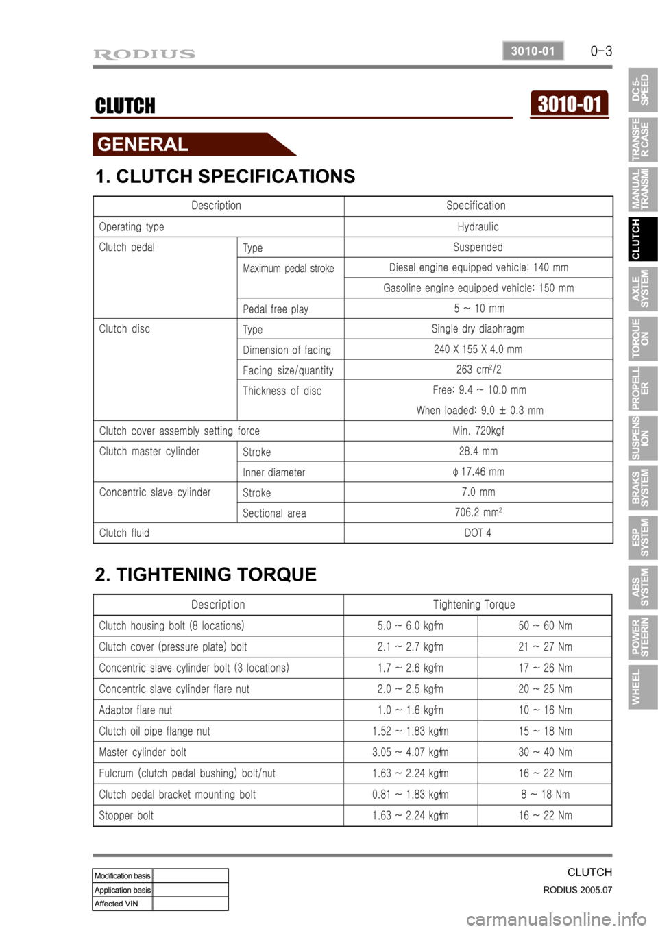
3010-01CLUTCH
1. CLUTCH SPECIFICATIONS
2. TIGHTENING TORQUE
Page 205 of 502

0-4
RODIUS 2005.07
3010-01
CLUTCH
1. OVERVIEW
1) Driving Elements
The driving elements consist of two flat surfaces machined to a smooth finish.
One of these is the rear face of the engine flywheel and the other is the clutch cover pressure
plate. The clutch pressure plate is fitted into a clutch steel cover, which is bolted to the flywheel.
2) Driven Elements
The driven element is the clutch disc with a splined hub which is free to slide lengthwise along
the splines of the input shaft. The driving and driven elements are held in contact by spring
pressure. This pressure is exerted by a diaphragm spring in the clutch cover pressure plate
assembly.
3) Operating Elements
The clutch control system consists of the clutch pedal, clutch master cylinder, concentric slave
cylinder. This system directly releases the clutch by using hydraulic pressure while the
conventional clutch system releases the clutch by using release lever and release fork. This
system provides higher efficiency than conventional clutch system, and its durability is superior.
Adaptor (mounted on transmission case) Concentric slave cylinder pipe (mounted inside o
f
transmission) Concentric slave cylinder (mounted inside of transmission)
Page 206 of 502
0-5
CLUTCH
RODIUS 2005.07
3010-01
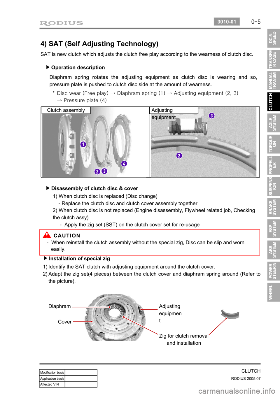
4) SAT (Self Adjusting Technology)
SAT is new clutch which adjusts the clutch free play according to the wearness of clutch disc. Operation description
▶
Diaphram spring rotates the adjusting equipment as clutch disc is wearing and so,
pressure plate is pushed to clutch disc side at the amount of wearness.
Disc wear (Free play) → Diaphram spring (1) → Adjusting equipme nt (2, 3)
→ Pressure plate (4)
*
Clutch assembly Adjusting
equipment
Disassembly of clutch disc & cover
▶
- When reinstall the clutch assembly without the special zig, Disc can be slip and worn
easily.
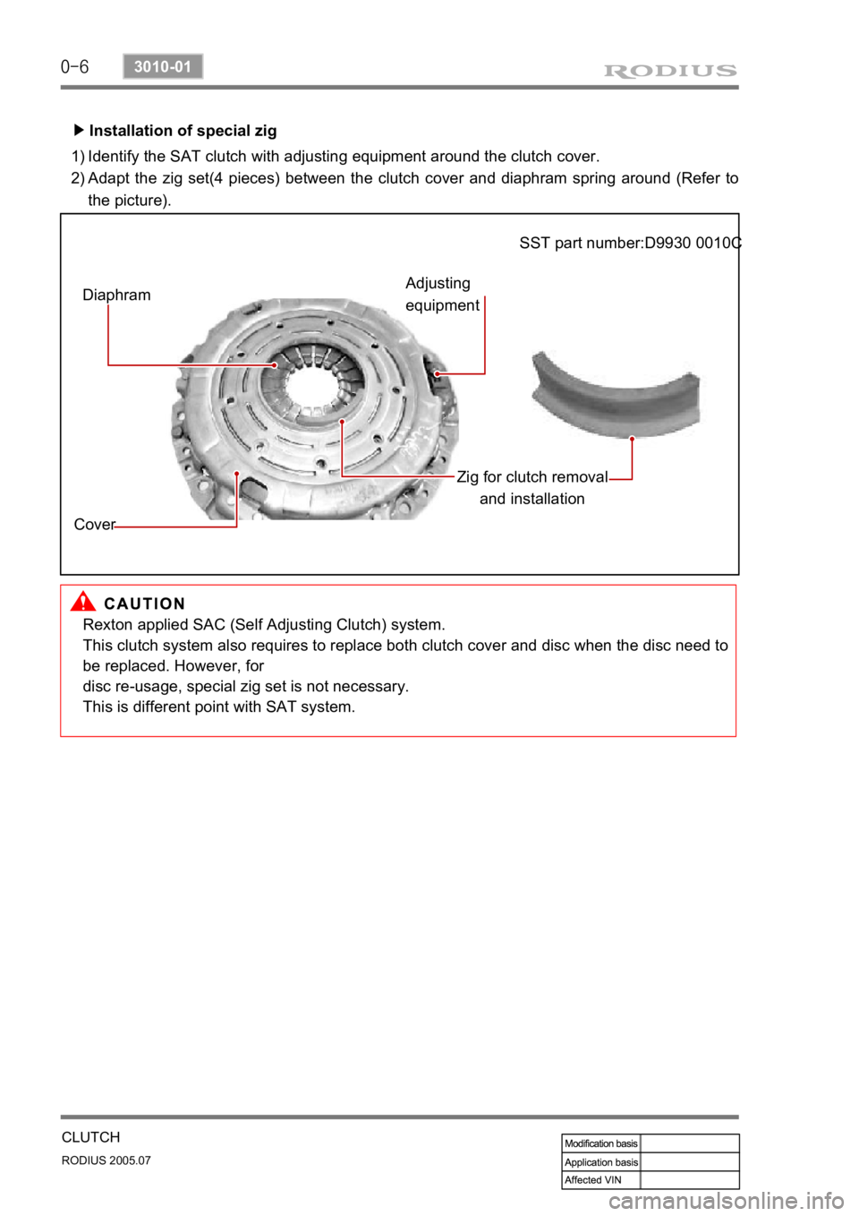
Installation of special zig
▶
Identify the SAT clutch with adjusting equipment around the clutch cover.
Adapt the zig set(4 pieces) between the clutch cover and diaphram spring around (Refer to
the picture).
1)
2)
Diaphram
Cover Zig for clutch removal and installationAdjusting
equipmen
t
1) When clutch disc is replaced (Disc change)
- Replace the clutch disc and clutch cover assembly together
2) When clutch disc is not replaced (Engine disassembly, Flywheel related job, Checking
the clutch assy)
- Apply the zig set (SST) on the clutch cover set for re-usage
Page 207 of 502
0-6
RODIUS 2005.07
3010-01
CLUTCH
Installation of special zig
▶
Identify the SAT clutch with adjusting equipment around the clutch cover.
Adapt the zig set(4 pieces) between the clutch cover and diaphram spring around (Refer to
the picture).
1)
2)
Diaphram
Cover Zig for clutch removal
and installation
Adjusting
equipment SST part number:D9930 0010C
Rexton applied SAC (Self Adjusting Clutch) system.
This clutch system also requires to replace both clutch cover and disc when the disc need to
be replaced. However, for
disc re-usage, special zig set is not necessary.
This is different point with SAT system.
Page 208 of 502
0-7
CLUTCH
RODIUS 2005.07
3010-01
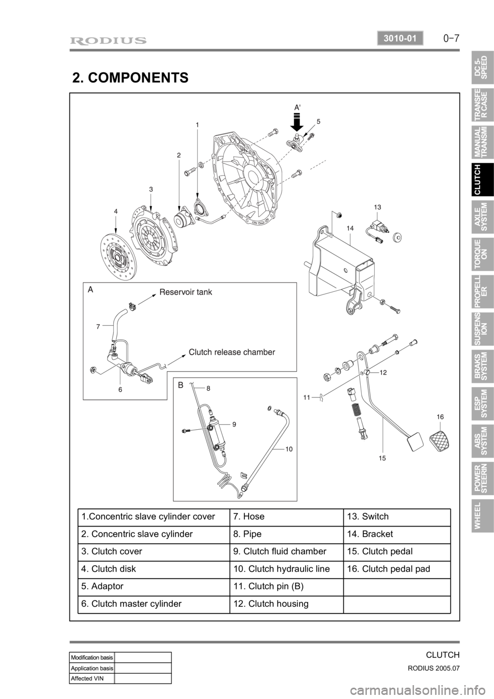
2. COMPONENTS
1.Concentric slave cylinder cover 7. Hose 13. Switch
2. Concentric slave cylinder 8. Pipe 14. Bracket
3. Clutch cover 9. Clutch fluid chamber 15. Clutch pedal
4. Clutch disk 10. Clutch hydraulic line 16. Clutch pedal pad
5. Adaptor 11. Clutch pin (B)
6. Clutch master cylinder 12. Clutch housing
Page 209 of 502
0-3
AXLE SYSTEM
RODIUS 2005.07
0000-00
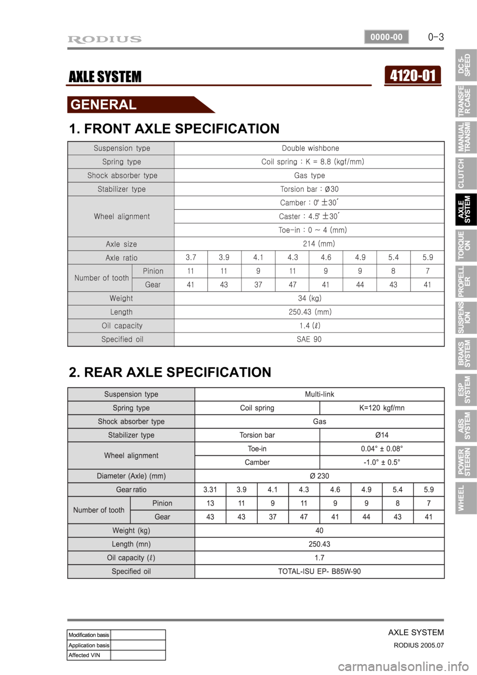
4120-01AXLE SYSTEM
1. FRONT AXLE SPECIFICATION
2. REAR AXLE SPECIFICATION
Page 210 of 502
0-3
TORQUE ON DEMAND
RODIUS 2005.07
3240-01
3240-01TOD(TORQUE ON DEMAND)
1. SPECIFICATIONS
Trending: parking sensors, change time, wiring, windshield wipers, wheel alignment, traction control, length


