SSANGYONG RODIUS 2005 Service Manual
RODIUS 2005
SSANGYONG
SSANGYONG
https://www.carmanualsonline.info/img/67/57522/w960_57522-0.png
SSANGYONG RODIUS 2005 Service Manual
Trending: air conditioning, check oil, ignition, fuel pressure, reset, turn signal, oil type
Page 271 of 502
0-19
ABS SYSTEM
RODIUS 2005.07
4892-01
(2) ABS Circuit Per ABS Operation Range
Hydraulic Pressure Circuit when ABS is Not Operating ▶
No Hydraulic Pressure Circuit when ABS is Operating ▶
The hydraulic pressure in the master cylinder increases through the vacuum booster and it is
delivered to the wheel via the normal open inlet valve. At this moment, the normally-closed
outlet valve is closed. The speed of the wheel that hydraulic pressure is delivered reduces
gradually
As hydraulic pressure on each wheel increases, the wheel tends to lock. In order to prevent the
wheel from locking, the hydraulic valve modulator operates the inlet valve control solenoid to
close the inlet valve and stop the hydraulic pressure increases. At this moment, the outlet valve
is closed. This procedure helps the wheel to maintain a stable hydraulic pressure.
Page 272 of 502

0-20
RODIUS 2005.07
4892-01
ABS SYSTEM
Pressure Decreases in the Circuit when ABS is Operating ▶
Pressure Increases in the Circuit when ABS is Operating ▶
Even when the hydraulic pressure on each circuit is stable, the wheel can be locked as the
wheel speed decreases. This is when the ABS ECU detects the wheel speed and the vehicle
speed and gives the optimized braking without locking the wheels. In order to prevent from
hydraulic pressure increases, the inlet valve is closed and the outlet valve is opened. Also, the
oil is sent to the low pressure changer and the wheel speed increases again. The ABS ECU
operates the pump to circulate the oil in the low pressure chamber to the master cylinder. This
may make the driver to feel the brake pedal vibration and some noises.
As the wheel speed increases, the inlet valve opens and the wheel’s pressure increases
due to the master cylinder pressure. The oil in the low pressure chamber circulates to the wheel
by the pump and the wheel speed decreases as the hydraulic pressure at wheel increases. This
operation continues repetitively until there are no signs that the ECU is locking the wheels.
When the ABS hydraulic pressure control takes place, there may be some vibration and noises
at the brake pedal.
Page 273 of 502
0-21
ABS SYSTEM
RODIUS 2005.07
4892-01
(3) COMPONENTS DESCRIPTION
HECU (Hydraulic & Electronic Control Unit) ▶
Motor Pump ▶
Valve Body ▶
HECU consists of motor pump (1), solenoid
valve (2) and ECU (3).
ECU connector has 47 pins and the numbe
r
of valves in valve body is 6 when equipped
with only ABS and 12 when equipped with
ESP system.
The motor is operated when ABS is
activated. The cam-shaped output shaft o
f
the motor enables the brake system to
receive and supply the brake fluid during the
motor operation.
The cam bushing is installed between
plungers and it draws and discharges the
brake fluid.
Page 274 of 502
0-22
RODIUS 2005.07
4892-01
ABS SYSTEM
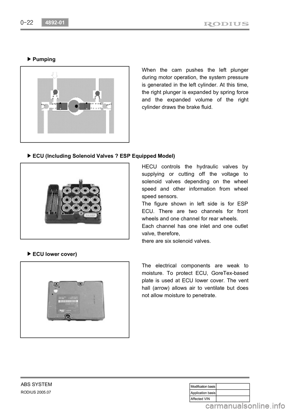
Pumping
▶
ECU (Including Solenoid Valves ? ESP Equipped Model)
▶
ECU lower cover)
▶
When the cam pushes the left plunger
during motor operation, the system pressure
is generated in the left cylinder. At this time,
the right plunger is expanded by spring force
and the expanded volume of the right
cylinder draws the brake fluid.
HECU controls the hydraulic valves by
supplying or cutting off the voltage to
solenoid valves depending on the wheel
speed and other information from wheel
speed sensors.
The figure shown in left side is for ESP
ECU. There are two channels for front
wheels and one channel for rear wheels.
Each channel has one inlet and one outlet
valve, therefore,
there are six solenoid valves.
The electrical components are weak to
moisture. To protect ECU, GoreTex-based
plate is used at ECU lower cover. The vent
hall (arrow) allows air to ventilate but does
not allow moisture to penetrate.
Page 275 of 502
0-3
POWER STEERING SYSTEM
RODIUS 2005.07
4610-00
4610-00POWER STEERING SYSTEM
1. SPECIFICATION
Page 276 of 502
0-4
RODIUS 2005.07
4610-00
POWER STEERING SYSTEM
2. TIGHTENING TORQUE
3. SPECIAL TOOLS AND EQUIPMENT
Page 277 of 502
0-5
POWER STEERING SYSTEM
RODIUS 2005.07
4610-00
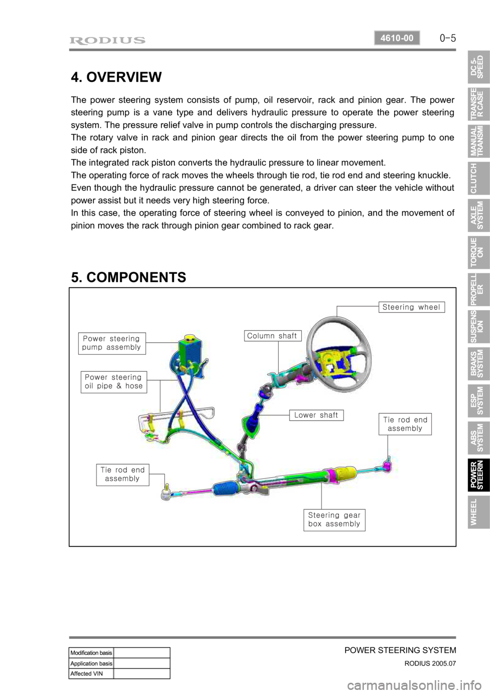
4. OVERVIEW
The power steering system consists of pump, oil reservoir, rack and pinion gear. The power
steering pump is a vane type and delivers hydraulic pressure to operate the power steering
system. The pressure relief valve in pump controls the discharging pressure.
The rotary valve in rack and pinion gear directs the oil from the power steering pump to one
side of rack piston.
The integrated rack piston converts the hydraulic pressure to linear movement.
The operating force of rack moves the wheels through tie rod, tie rod end and steering knuckle.
Even though the hydraulic pressure cannot be generated, a driver can steer the vehicle without
power assist but it needs very high steering force.
In this case, the operating force of steering wheel is conveyed to pinion, and the movement o
f
pinion moves the rack through pinion gear combined to rack gear.
5. COMPONENTS
Page 278 of 502
0-6
RODIUS 2005.07
4610-00
POWER STEERING SYSTEM
1. COMPONENTS OF POWER STEERING ASSEMBLY
Page 279 of 502
0-7
POWER STEERING SYSTEM
RODIUS 2005.07
4610-00
2. POWER STEERING GEAR BOX ASSEMBLY
The power steering gear consists of power cylinder and control valve.
The power cylinder has cylinder, piston and piston rod. The control valve directs the oil to one
end face of the piston to enhance the steering force.
The control valve controls the directions and operations of power cylinder.
Additionally, the safety check valve is installed so that the system can be operated manually
when the system is defective.
Page 280 of 502
0-8
RODIUS 2005.07
4610-00
POWER STEERING SYSTEM
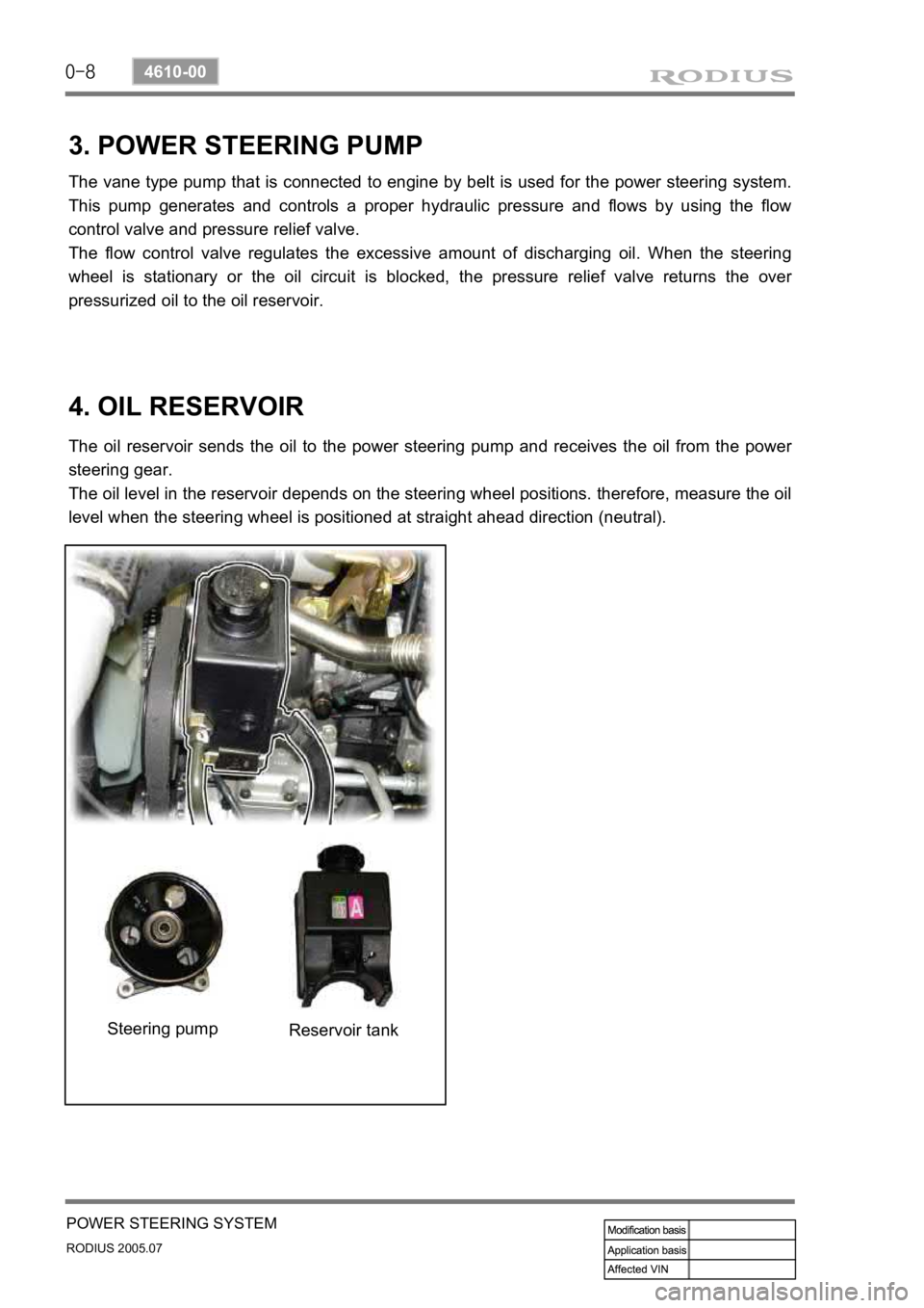
3. POWER STEERING PUMP
The vane type pump that is connected to engine by belt is used for the power steering system.
This pump generates and controls a proper hydraulic pressure and flows by using the flow
control valve and pressure relief valve.
The flow control valve regulates the excessive amount of discharging oil. When the steering
wheel is stationary or the oil circuit is blocked, the pressure relief valve returns the ove
r
pressurized oil to the oil reservoir.
4. OIL RESERVOIR
The oil reservoir sends the oil to the power steering pump and receives the oil from the power
steering gear.
The oil level in the reservoir depends on the steering wheel positions. therefore, measure the oil
level when the steering wheel is positioned at straight ahead direction (neutral).
Steering pump Reservoir tank
Trending: oil level, load capacity, remote start, hood open, window, clock, lights


