EGR SSANGYONG TURISMO 2013 Workshop Manual
[x] Cancel search | Manufacturer: SSANGYONG, Model Year: 2013, Model line: TURISMO, Model: SSANGYONG TURISMO 2013Pages: 796, PDF Size: 78.99 MB
Page 533 of 796

09-6
Shift lever (R position)
Sends reverse signal to PAS unit
1. Overview
The parking aid system (PAS) is a supplementary device which detects the distance to any obstacle
with the ultrasonic sensors equipped to the rear bumper and warns the driver with alarm sounds, when
the vehicle is moving backward.
The system emits the ultrasonic wave signals from the sensors on the rear bumper with a specific
interval and detects the reflected signals from obstacles.
The alarm interval becomes shorter as the obstacle approaches to assure the safety distance and to
facilitate parking of the vehicle.
2. Layout
ICM box
Buzzer integrated into ICM box
(indicates distance as alarm interval)
Page 545 of 796
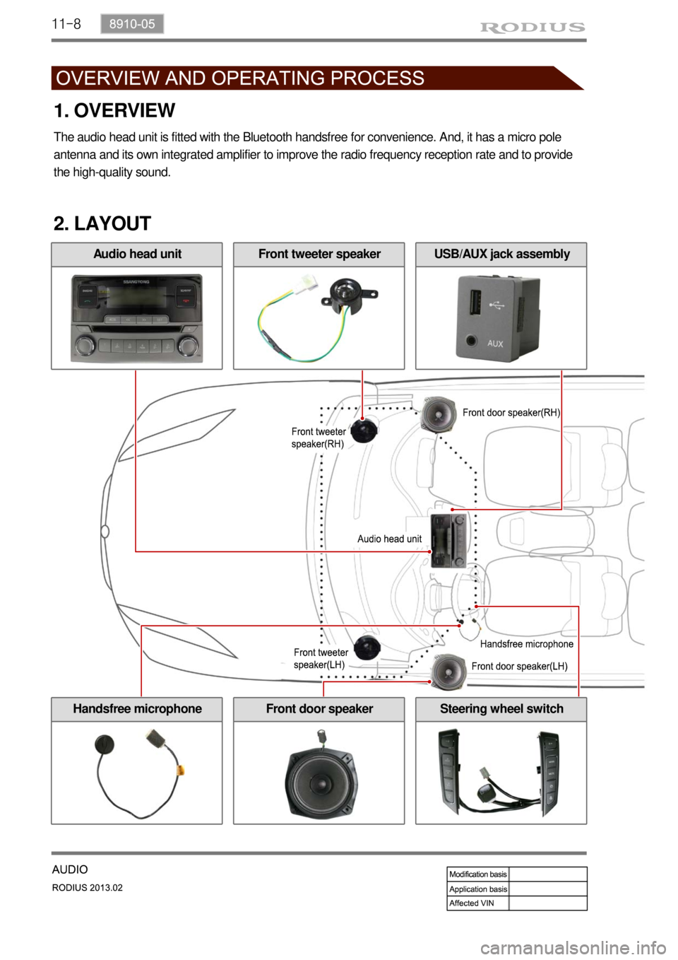
11-8
Front door speaker
2. LAYOUT
Handsfree microphoneSteering wheel switch
1. OVERVIEW
The audio head unit is fitted with the Bluetooth handsfree for convenience. And, it has a micro pole
antenna and its own integrated amplifier to improve the radio frequency reception rate and to provide
the high-quality sound.
Audio head unitFront tweeter speakerUSB/AUX jack assembly
Page 594 of 796
03-8
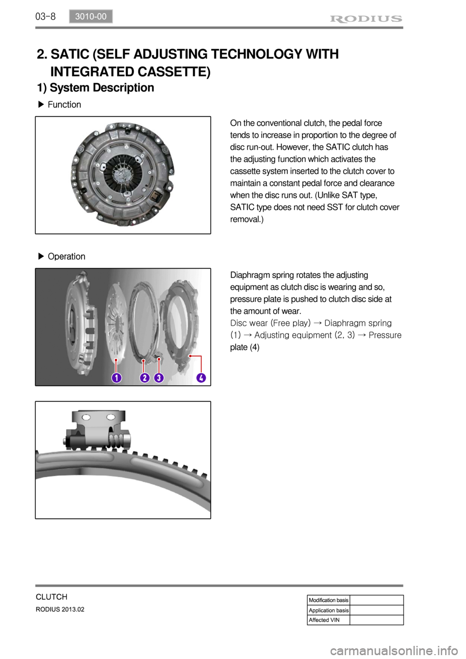
2. SATIC (SELF ADJUSTING TECHNOLOGY WITH
INTEGRATED CASSETTE)
1) System Description
▶ Function
On the conventional clutch, the pedal force
tends to increase in proportion to the degree of
disc run-out. However, the SATIC clutch has
the adjusting function which activates the
cassette system inserted to the clutch cover to
maintain a constant pedal force and clearance
when the disc runs out. (Unlike SAT type,
SATIC type does not need SST for clutch cover
removal.)
▶ Operation
Diaphragm spring rotates the adjusting
equipment as clutch disc is wearing and so,
pressure plate is pushed to clutch disc side at
the amount of wear.
Disc wear (Free play) → Diaphragm spring
(1) → Ad
justing equipment (2, 3) → Pressure
plate (4)
Page 608 of 796

05-93240-01
4. IWE LOCKING HUB SYSTEM
1) Overview
The vacuum locking hub uses the IWE (Integrated Wheel End) system, and in this system, the
vacuum is generated only within the hub actuator.
It is structured to transmit power to the front section after the actuator hub is engaged following
the release of vacuum from the drive shaft end gear and the hub end gear.
Booster
Vacuum pump
Vacuum generation process in front hub actuator ▶
Page 630 of 796
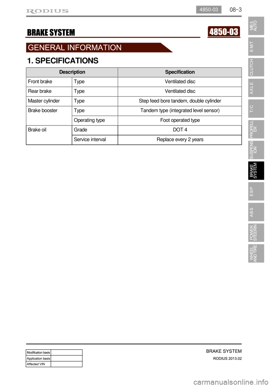
08-34850-03
Brake oil Grade DOT 4
Service interval Replace every 2 years
1. SPECIFICATIONS
Description Specification
Front brake Type Ventilated disc
Rear brake Type Ventilated disc
Master cylinder Type Step feed bore tandem, double cylinder
Brake booster Type Tandem type (integrated level sensor)
Operating type Foot operated type
Page 649 of 796

09-34891-01
1. SPECIFICATIONS
1) Pressure Sensor
UnitDescription
Location
ABS ESP
HECU
(Hydraulic &
Electronic Control
Unit) CPU:MCU60 (32bit)
Clock Frequency:
28 MHz
Memory: 128~256 KB CPU:MCU60 (32bit)
Clock Frequency:
28 MHz
Memory:256~512 KB Under the front washer
reservoir
Wheel Speed
SensorActive type wheel speed
sensorActive type wheel speed
sensorOn each wheel
Front air gap:
0.3 ~ 1.3mm,
Rear air gap:
0.3 ~ 1.3 mm
Steering Wheel
Angle SensorN/AMaximum angular speed:
1500°/sec
Operating voltage:
9~16 VUnder the steering
wheel
Sensor ClusterN/AIntegrated with yaw rate
sensor and lateral sensorUnder the audio
assembly
Pressure Sensor
N/A Analog outputUnder the master
cylinder
Description Specification
Supplying voltage approx. 5 V (4.75~5.25 V)
Max. pressure 350 bar
Page 652 of 796
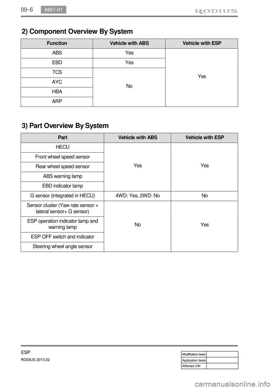
09-6
2) Component Overview By System
Function Vehicle with ABS Vehicle with ESP
ABS Yes
Yes EBD Yes
TCS
No AYC
HBA
ARP
3) Part Overview By System
Part Vehicle with ABS Vehicle with ESP
HECU
Yes Yes Front wheel speed sensor
Rear wheel speed sensor
ABS warning lamp
EBD indicator lamp
G sensor (integrated in HECU) 4WD: Yes, 2WD: No No
Sensor cluster (Yaw rate sensor +
lateral sensor+ G sensor)
No Yes ESP operation indicator lamp and
warning lamp
ESP OFF switch and indicator
Steering wheel angle sensor
Page 655 of 796
09-94891-01
1. ESP (Electronic Stability Program)
As the single-track vehicle model used for the calculations is only valid for a vehicle moving forward,
ESP intervention never takes place during backup.
The ESP system includes the ABS/EBD and ASR systems allowing the system to be able to operate
depending to the vehicle driving conditions.
1) Overview
For example, when the brakes are applied during cornering at the speed of 100 km/h, the ABS will
operate at the same time the ASR or ABD systems operate to reduce the power from the slipping
wheel. And when yaw rate sensor detects the rate exceeding 4 degree/seconds, the ESP system
is activated to apply the brake force to the corresponding wheel to compensate the yaw moment
with the vehicle stability control function. This may cause a problem in vehicle control system due
to multi-operation of systems, thus there is a priority as below:
TCS (ASR or ABD) > ESP > ABS (This is subject to the driving and vehicle conditions.)
Page 695 of 796

11-134610-00
1. OVERVIEW
The power steering has been designed to make the wheel move more easily than in a manual steering
system. The hydraulic power assists the process utilizing hydraulic fluid. The fluid increases pressure
in the power steering pump and aids the movement of the steering mechanism. The power steering
system consists of pump, oil reservoir, rack and gear box. The power steering pump is a vane type
and delivers hydraulic pressure to operate the power steering system. The pressure relief valve in the
pump controls the discharging pressure. The rotary valve in the rack and the pinion gear directs the oil
from the power steering pump to one side of the rack piston. The integrated rack piston converts the
hydraulic pressure to linear movement. The operating force of the rack moves the wheels through the
tie rod, the tie rod end and the steering knuckle. Even though the hydraulic pressure cannot be
generated, a driver can steer the vehicle without power assist but it needs very high steering force. In
this case, the operating force of the steering wheel is conveyed to the pinion, and the movement of the
pinion moves the rack through the pinion gear combined to the rack gear.
Page 700 of 796

12-54170-01
1. OVERVIEW
A radial tire uses a cord angle of 90 degrees. That is, the cord material runs in a radial or direct line
from one bead to the other across the tread. In addition, a radial tire has a belt overwrap under the
tread surface to provide greater structural stability. The belt overwrap of a radial tire distortion while the
radial structure enables high speed driving.
Tire supports the weight of the vehicle, reduces the impact from the road and at the same time,
transmits the power to propel, brake and steer on the road. It also functions to maintain a
vehicle’s movement. In order to complete such tasks, a tire must be structured to be a resilient
vessel of air.
There is wear limit mark on the tire, which protrudes as a strip shape located approximately 1.6 mm
from the groove bottom. This wear limit mark is not seen from the outside so there is additional
"▲" mark on the shoulder to let the driver find the wear mark easily. To measure the tire groove
depth, measure at any point other than the point which has a wear limit mark.
The tire is worn unevenly according to the driver's driving habit, improper servicing, low tire inflation
pressure, changed tire location, etc.
1) Structure of Tire
Tread
This thick layer of rubber provides the interface
between the tire and the road. Wear-resistant
rubber is used to protect the carcass and belt
against fractures and impacts and to deliver a
long driving life.
Shoulder
Located between the tread and sidewall, the
shoulder rubber is the thickest so that the
design must allow for the easy diffusion of heat
generated within the tire while driving.
Sidewall
The part between the shoulder and bead, the
flexible sidewall protects the carcass and
enhances the ride. A tire’s type, size,
structure, pattern, manufacturing company,
product name and various characters are
indicated here. Bead
The bead attaches the tire to the rim and wraps
the end of the cord fabric. Comprised of the bead
wire, core, flipper and other parts, the bead is
generally designed to be slightly tight around the
rim so that in the case of a sudden drop in
inflation pressure, the tire will not fall off the rim.
Carcass
As the most important framework of a tire, the
entire inner layer of cord fabric is called the
carcass. The carcass acts to support air
pressure, vertical load and absorb shocks.
Valve
Belt
Bead core