SUBARU CROSSTREK 2017 1.G Owners Manual
CROSSTREK 2017 1.G
SUBARU
SUBARU
https://www.carmanualsonline.info/img/17/7197/w960_7197-0.png
SUBARU CROSSTREK 2017 1.G Owners Manual
Trending: headlight bulb, change key battery, height, boot, air filter, coolant reservoir, battery
Page 531 of 572
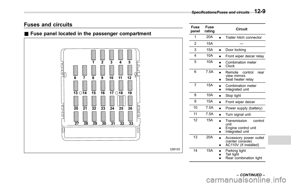
Fuses and circuits
&Fuse panel located in the passenger compartment
Fuse
panelFuse
ratingCircuit
1 20A
.Trailer hitch connector
2 15A—
3 15A
.Door locking
4 10A
.Front wiper deicer relay
5 10A
.Combination meter
.Clock
6 7.5A
.Remote control rear
view mirrors
.Seat heater relay
7 15A
.Combination meter
.Integrated unit
8 10A
.Stop light
9 15A
.Front wiper deicer
10 7.5A
.Power supply (battery)
11 7.5A
.Turn signal unit
12 15A
.Transmission control
unit
.Engine control unit
.Integrated unit
13 20A
.Accessory power outlet
(center console)
.AC110V (If installed)
14 15A
.Parking light
.Tail light
.Rear combination light Specifications/Fuses and circuits
–CONTINUED–
12-9
Page 532 of 572
Specifications/Fuses and circuits
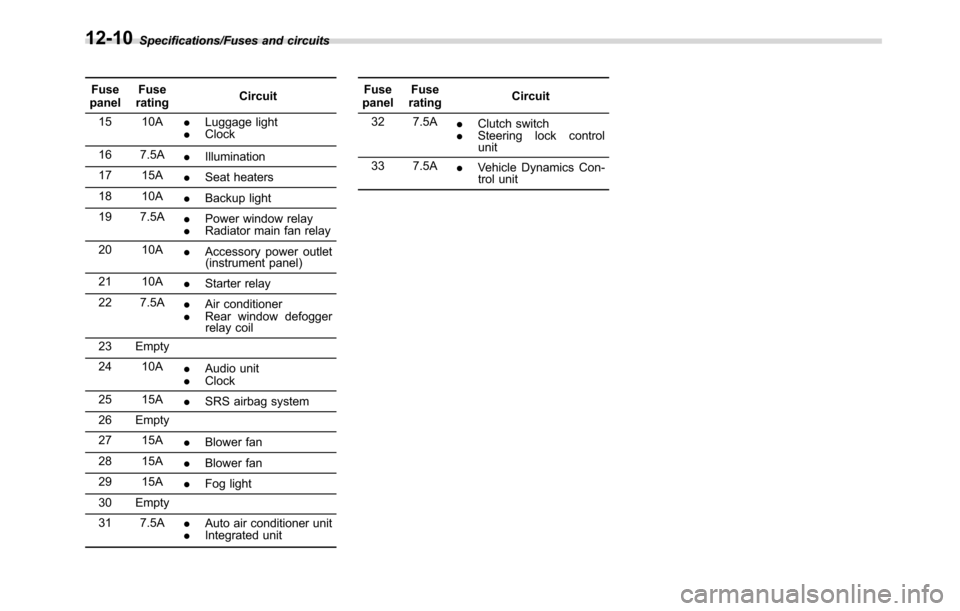
Fuse
panelFuse
ratingCircuit
15 10A
.Luggage light
.Clock
16 7.5A
.Illumination
17 15A
.Seat heaters
18 10A
.Backup light
19 7.5A
.Power window relay
.Radiator main fan relay
20 10A
.Accessory power outlet
(instrument panel)
21 10A
.Starter relay
22 7.5A
.Air conditioner
.Rear window defogger
relay coil
23 Empty
24 10A
.Audio unit
.Clock
25 15A
.SRS airbag system
26 Empty
27 15A
.Blower fan
28 15A
.Blower fan
29 15A
.Fog light
30 Empty
31 7.5A
.Auto air conditioner unit
.Integrated unitFuse
panelFuse
ratingCircuit
32 7.5A
.Clutch switch
.Steering lock control
unit
33 7.5A
.Vehicle Dynamics Con-
trol unit
12-10
Page 533 of 572
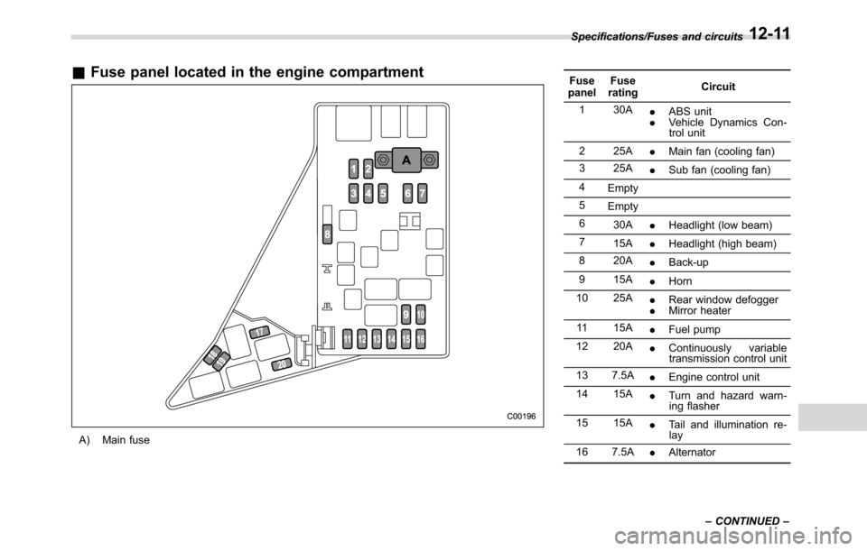
&Fuse panel located in the engine compartment
A) Main fuseFuse
panelFuse
ratingCircuit
1 30A
.ABS unit
.Vehicle Dynamics Con-
trol unit
2 25A
.Main fan (cooling fan)
3 25A
.Sub fan (cooling fan)
4
Empty
5
Empty
6
30A
.Headlight (low beam)
7
15A
.Headlight (high beam)
8 20A
.Back-up
9 15A
.Horn
10 25A
.Rear window defogger
.Mirror heater
11 15A
.Fuel pump
12 20A
.Continuously variable
transmission control unit
13 7.5A
.Engine control unit
14 15A
.Turn and hazard warn-
ing flasher
15 15A
.Tail and illumination re-
lay
16 7.5A
.Alternator Specifications/Fuses and circuits
–CONTINUED–
12-11
Page 534 of 572
Specifications/Fuses and circuits
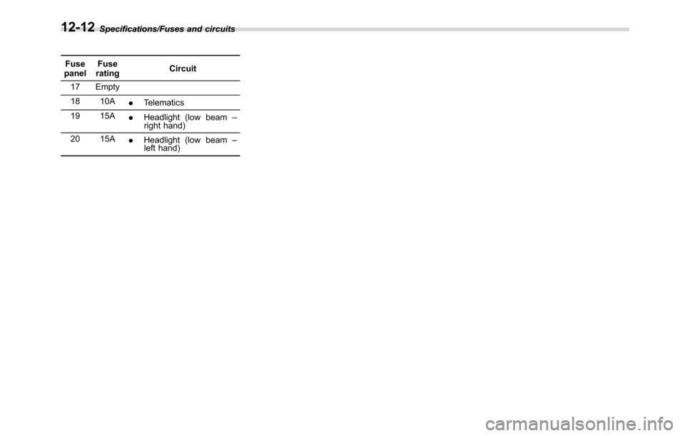
Fuse
panelFuse
ratingCircuit
17 Empty
18 10A
.Telematics
19 15A
.Headlight (low beam–
right hand)
20 15A
.Headlight (low beam–
left hand)
12-12
Page 535 of 572
Bulb chart
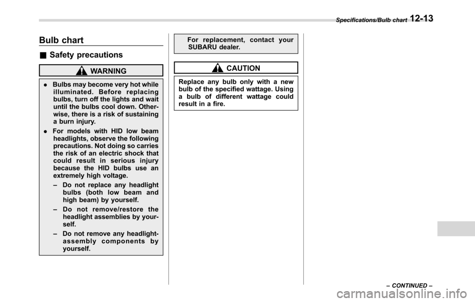
&Safety precautions
WARNING
.Bulbs may become very hot while
illuminated. Before replacing
bulbs, turn off the lights and wait
until the bulbs cool down. Other-
wise, there is a risk of sustaining
a burn injury.
.For models with HID low beam
headlights, observe the following
precautions. Not doing so carries
the risk of an electric shock that
could result in serious injury
because the HID bulbs use an
extremely high voltage.
–Do not replace any headlight
bulbs (both low beam and
high beam) by yourself.
–Do not remove/restore the
headlight assemblies by your-
self.
–Do not remove any headlight-
assembly components by
yourself.For replacement, contact your
SUBARU dealer.
CAUTION
Replace any bulb only with a new
bulb of the specified wattage. Using
a bulb of different wattage could
result in a fire.
Specifications/Bulb chart
–CONTINUED–12-13
Page 536 of 572
Specifications/Bulb chart
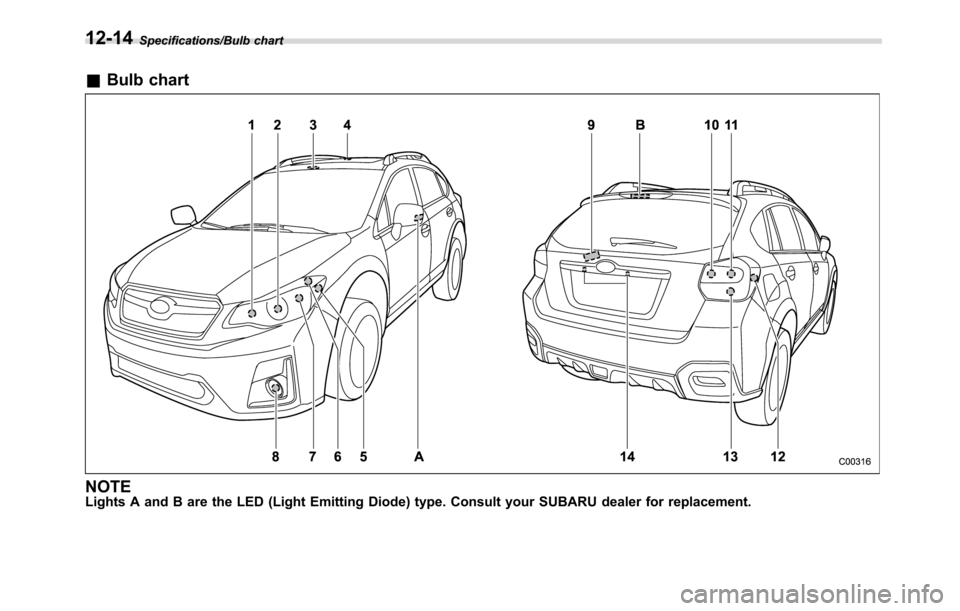
&Bulb chart
NOTELights A and B are the LED (Light Emitting Diode) type. Consult your SUBARU dealer for replacement.
12-14
Page 537 of 572
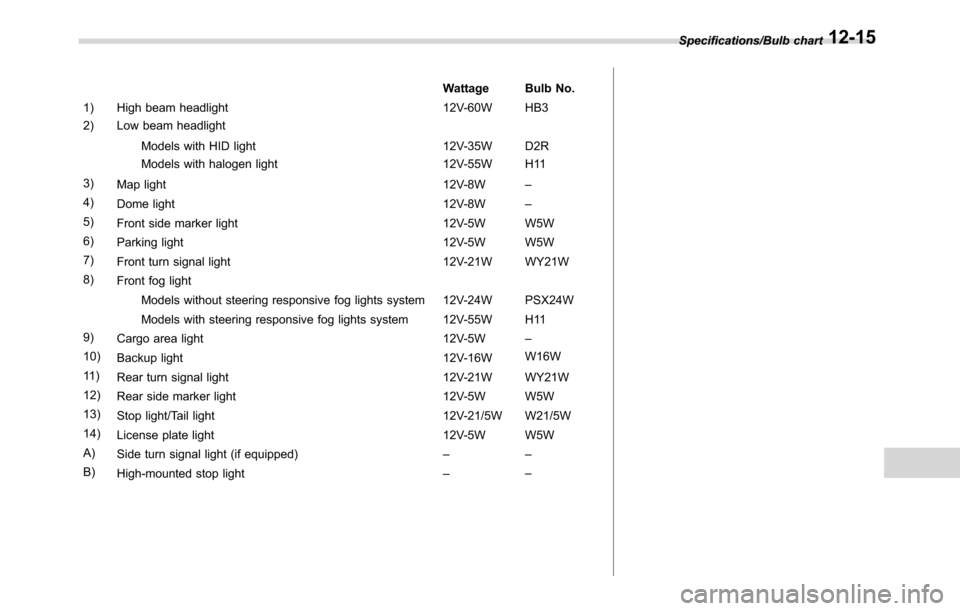
Wattage Bulb No.
1) High beam headlight 12V-60W HB3
2) Low beam headlight
Models with HID light 12V-35W D2R
Models with halogen light 12V-55W H11
3)
Map light 12V-8W–
4)
Dome light 12V-8W–
5)
Front side marker light 12V-5W W5W
6)
Parking light 12V-5W W5W
7)
Front turn signal light 12V-21W WY21W
8)
Front fog light
Models without steering responsive fog lights system 12V-24W PSX24W
Models with steering responsive fog lights system 12V-55W H11
9)
Cargo area light 12V-5W–
10)
Backup light 12V-16WW16W
11 )
Rear turn signal light 12V-21W WY21W
12)
Rear side marker light 12V-5W W5W
13)
Stop light/Tail light 12V-21/5W W21/5W
14)
License plate light 12V-5W W5W
A)
Side turn signal light (if equipped)––
B)
High-mounted stop light––Specifications/Bulb chart
12-15
Page 538 of 572
Specifications/Vehicle identification
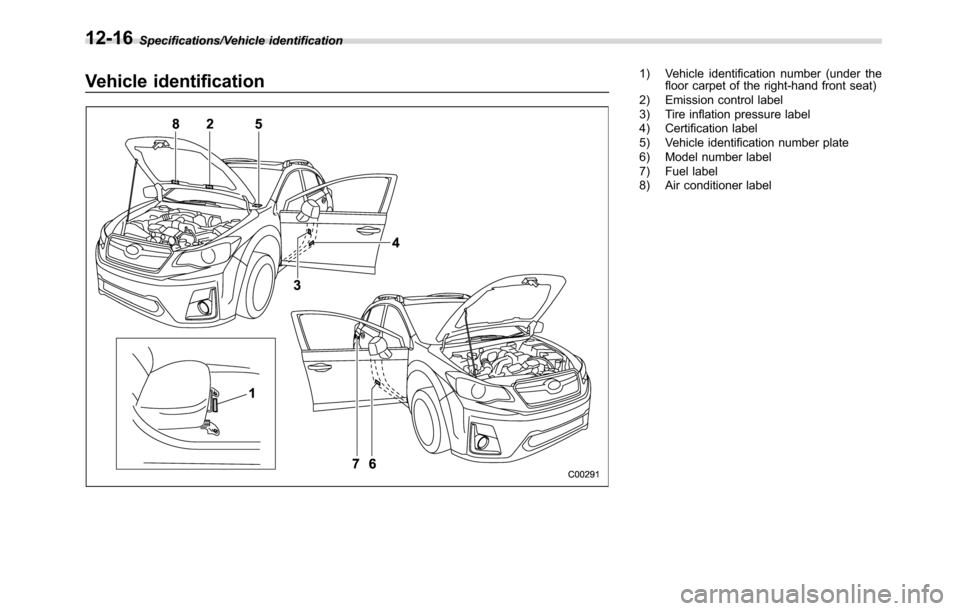
Vehicle identification1) Vehicle identification number (under the
floor carpet of the right-hand front seat)
2) Emission control label
3) Tire inflation pressure label
4) Certification label
5) Vehicle identification number plate
6) Model number label
7) Fuel label
8) Air conditioner label
12-16
Page 539 of 572
For U.S.A............................................................ 13-2
Tire information.................................................. 13-2
Tire labeling....................................................... 13-2
Recommended tire inflation pressure.................. 13-4
Glossary of tire terminology............................... 13-5
Tire care–maintenance and safety
practices........................................................ 13-10
Vehicle load limit–how to determine................ 13-10
Determining compatibility of tire and vehicle
load capacities............................................... 13-13Adverse safety consequences of overloading
on handling and stopping and on tires........... 13-14
Steps for Determining Correct Load Limit......... 13-14Uniform tire quality grading standards.......... 13-15Treadwear....................................................... 13-15
Traction AA, A, B, C......................................... 13-15
Temperature A, B, C......................................... 13-15
Reporting safety defects (U.S.A.)................... 13-16
Supplement...................................................... 13-17
Declaration of conformity with FCC rules......... 13-17
Consumer information and Reporting safety defects
13
Page 540 of 572
Consumer information and Reporting safety defects/For U.S.A.
For U.S.A.
The following information has been
compiled according to Code of
Federal Regulations“Title 49, Part
575”.
Tire information
&Tire labeling
Many markings (e.g. Tire size, Tire
Identification Number or TIN) are
placed on the sidewall of a tire by
tire manufacturers. These markings
can provide you with useful infor-
mation on the tire.
!Tire size
Your vehicle comes equipped with
P-Metric tire size. It is important to
understand the sizing system in
selecting the proper tire for your
vehicles. Here is a brief review of
the tire sizing system with a break-
down of its individual elements.
!P Metric
With the P-Metric system, Section
Width is measured in millimeters.
To convert millimeters into inches,
divide by 25.4. The Aspect Ratio
(Section Height divided by Section
Width) helps provide more dimen-
sional information about the tire
size.
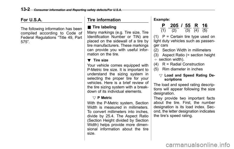
Example:
(1) P = Certain tire type used on
light duty vehicles such as passen-
ger cars
(2) Section Width in millimeters
(3) Aspect Ratio (= section height
7section width).
(4) R = Radial Construction
(5) Rim diameter in inches
!Load and Speed Rating De-
scriptions
The load and speed rating descrip-
tions will appear following the size
designation.
They provide two important facts
about the tire. First, the number
designation is its load index. Sec-
ond, the letter designation indicates
the tire’s speed rating.
13-2
Trending: ground clearance, compression ratio, coolant level, Interval, mirror, Cut transmission, key battery
