SUBARU FORESTER 1999 Service Repair Manual
Manufacturer: SUBARU, Model Year: 1999, Model line: FORESTER, Model: SUBARU FORESTER 1999Pages: 345, PDF Size: 5.6 MB
Page 291 of 345
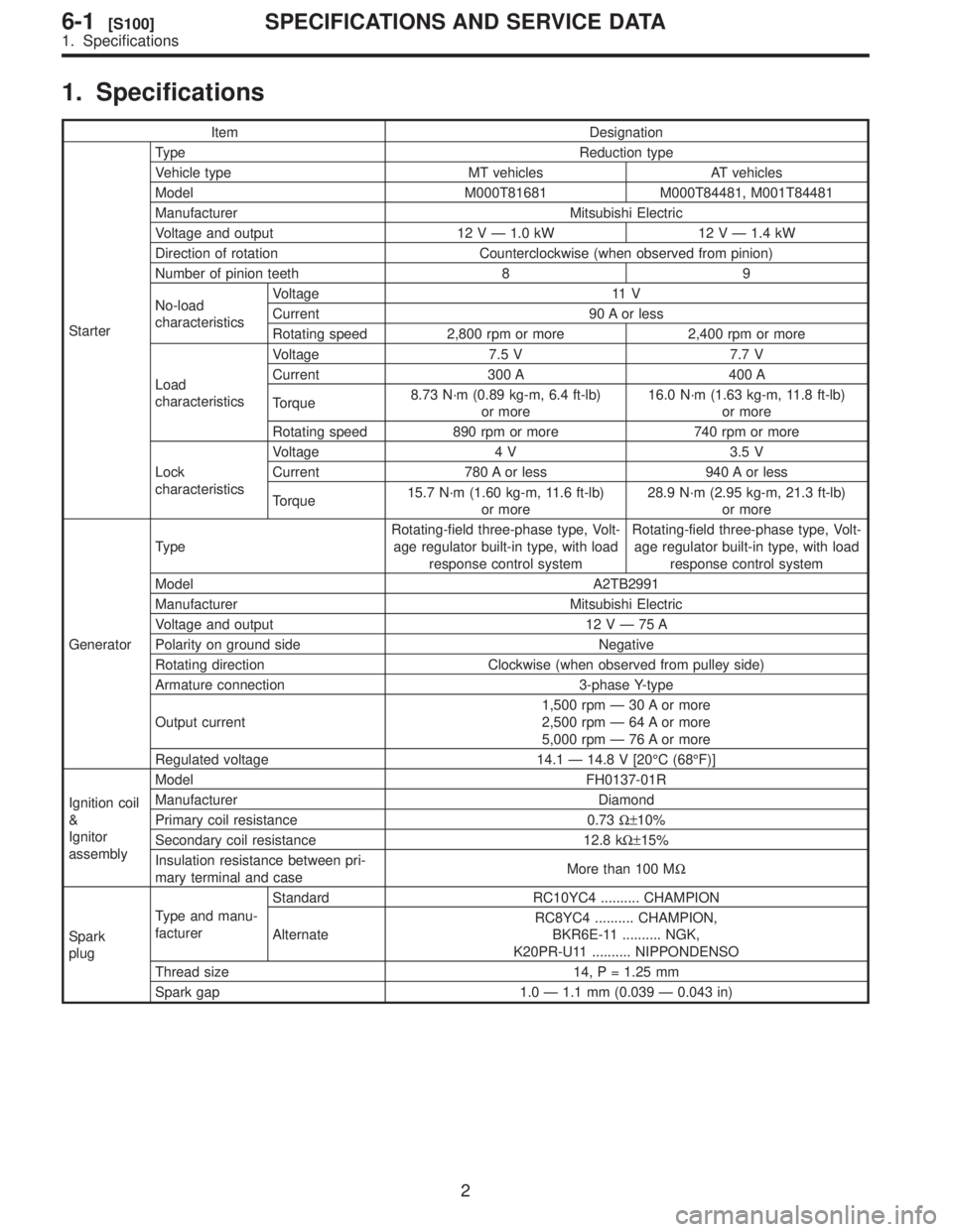
1.
Item
Starter T
V
Model
Manufacturer
V
2
Direction
Number
No-load
characteristics V
Current
Rotating
Load
characteristics V
Current
T
8.73
or 16.0
or
Rotating
Lock
characteristics V
Current
T
15.7
or 28.9
or
Generator T
Rotating-field
age response Rotating-field
age response
Model
Manufacturer
V 2V\3207
Polarity
Rotating
Armature
Output 1,500
2,500
5,000
Regulated
Ignition
&
Ignitor
assembly Model
Manufacturer
Primary
W\26110%
Secondary W\26115%
Insulation
mary More
W
Spark
plug T
facturer
Standard
Alternate
RC8YC4
BKR6E-1
K20PR-U1
Thread
Spark
2
6-1[S100]SPECIFICA
1.
Page 292 of 345
![SUBARU FORESTER 1999 Service Repair Manual 1.
H6M0492B
\(1\)
\(2\)
\(3\)
\(4\)
\(5\)
\(6\)\(7\)
\(8\)
\(9\)
\(10\)
\(1
\(12\)\(13\)
\(14\)
\(15\)
\(16\)
\(17\)
3
[C100]6-1COMPONENT
1. SUBARU FORESTER 1999 Service Repair Manual 1.
H6M0492B
\(1\)
\(2\)
\(3\)
\(4\)
\(5\)
\(6\)\(7\)
\(8\)
\(9\)
\(10\)
\(1
\(12\)\(13\)
\(14\)
\(15\)
\(16\)
\(17\)
3
[C100]6-1COMPONENT
1.](/img/17/57427/w960_57427-291.png)
1.
H6M0492B
\(1\)
\(2\)
\(3\)
\(4\)
\(5\)
\(6\)\(7\)
\(8\)
\(9\)
\(10\)
\(1
\(12\)\(13\)
\(14\)
\(15\)
\(16\)
\(17\)
3
[C100]6-1COMPONENT
1.
Page 293 of 345
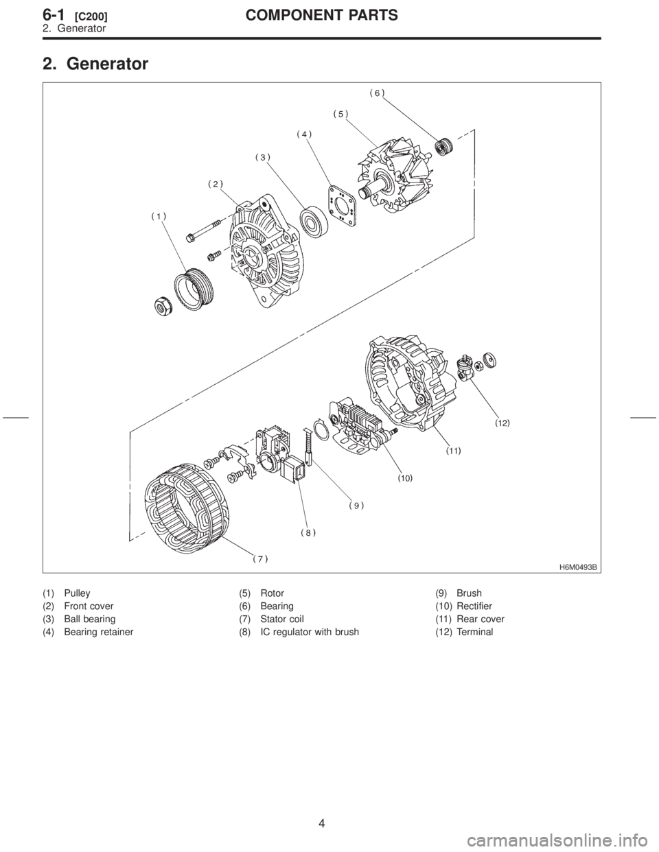
2. Generator
H6M0493B
(1) Pulley
(2) Front cover
(3) Ball bearing
(4) Bearing retainer(5) Rotor
(6) Bearing
(7) Stator coil
(8) IC regulator with brush(9) Brush
(10) Rectifier
(11) Rear cover
(12) Terminal
4
6-1[C200]COMPONENT PARTS
2. Generator
Page 294 of 345
![SUBARU FORESTER 1999 Service Repair Manual 3.
S6M0329A
\(1\)
\(2\)
\(3\)\(4\)T
T:
22\2612\2610.2,\2611.4\)
5
[C300]6-1COMPONENT
3. SUBARU FORESTER 1999 Service Repair Manual 3.
S6M0329A
\(1\)
\(2\)
\(3\)\(4\)T
T:
22\2612\2610.2,\2611.4\)
5
[C300]6-1COMPONENT
3.](/img/17/57427/w960_57427-293.png)
3.
S6M0329A
\(1\)
\(2\)
\(3\)\(4\)T
T:
22\2612\2610.2,\2611.4\)
5
[C300]6-1COMPONENT
3.
Page 295 of 345
![SUBARU FORESTER 1999 Service Repair Manual 1. Starter
A: REMOVAL AND INSTALLATION
1) Disconnect battery ground cable.
G6M0095
2) Remove air cleaner case and air intake duct.
<Ref. to 2-7 [W1A0].>
H2M2931
3) Remove air intake chamber stay.
S2M0 SUBARU FORESTER 1999 Service Repair Manual 1. Starter
A: REMOVAL AND INSTALLATION
1) Disconnect battery ground cable.
G6M0095
2) Remove air cleaner case and air intake duct.
<Ref. to 2-7 [W1A0].>
H2M2931
3) Remove air intake chamber stay.
S2M0](/img/17/57427/w960_57427-294.png)
1. Starter
A: REMOVAL AND INSTALLATION
1) Disconnect battery ground cable.
G6M0095
2) Remove air cleaner case and air intake duct.
H2M2931
3) Remove air intake chamber stay.
S2M0900A
S2M0901A
4) Disconnect connector and terminal from starter.
S6M0002A
(A) Terminal
(B) Connector
5) Remove starter from transmission.
G2M0309
6) Install in the reverse order of removal.
Tightening torque:
50
±4 N´m (5.1±0.4 kg-m, 37±2.9 ft-lb)
G2M0309
B: TEST
1. SWITCH ASSEMBLY OPERATION
1) Connect terminal S of switch assembly to posi-
tive terminal of battery with a lead wire, and starter
body to ground terminal of battery. Pinion should
be forced endwise on shaft.
CAUTION:
With pinion forced endwise on shaft, starter
motor can sometimes rotate because current
flows, through pull-in coil, to motor. This is not
a problem.
6
6-1[W1A0]SERVICE PROCEDURE
1. Starter
Page 296 of 345
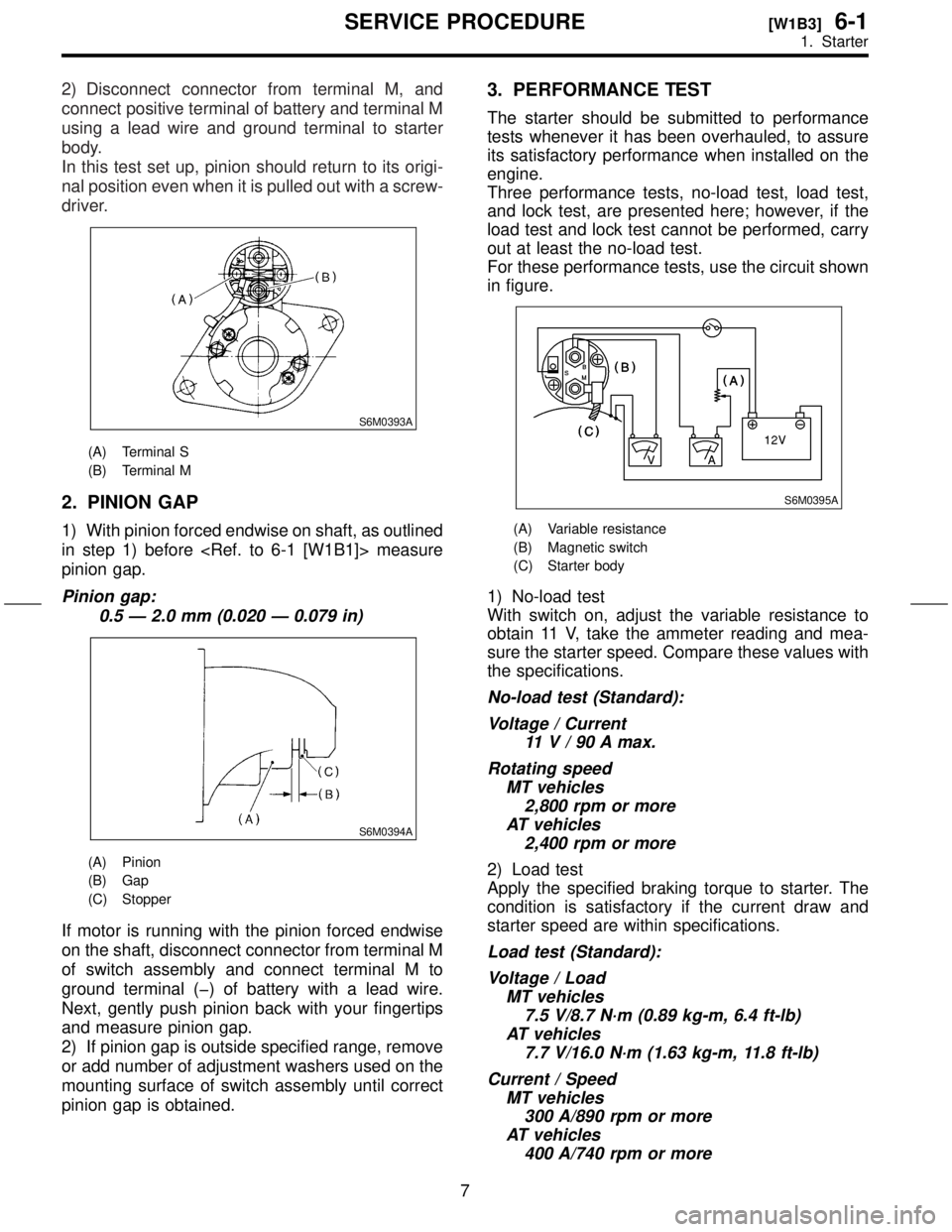
2) Disconnect connector from terminal M, and
connect positive terminal of battery and terminal M
using a lead wire and ground terminal to starter
body.
In this test set up, pinion should return to its origi-
nal position even when it is pulled out with a screw-
driver.
S6M0393A
(A) Terminal S
(B) Terminal M
2. PINION GAP
1) With pinion forced endwise on shaft, as outlined
in step 1) before
pinion gap.
Pinion gap:
0.5 Ð 2.0 mm (0.020 Ð 0.079 in)
S6M0394A
(A) Pinion
(B) Gap
(C) Stopper
If motor is running with the pinion forced endwise
on the shaft, disconnect connector from terminal M
of switch assembly and connect terminal M to
ground terminal (þ) of battery with a lead wire.
Next, gently push pinion back with your fingertips
and measure pinion gap.
2) If pinion gap is outside specified range, remove
or add number of adjustment washers used on the
mounting surface of switch assembly until correct
pinion gap is obtained.
3. PERFORMANCE TEST
The starter should be submitted to performance
tests whenever it has been overhauled, to assure
its satisfactory performance when installed on the
engine.
Three performance tests, no-load test, load test,
and lock test, are presented here; however, if the
load test and lock test cannot be performed, carry
out at least the no-load test.
For these performance tests, use the circuit shown
in figure.
S6M0395A
(A) Variable resistance
(B) Magnetic switch
(C) Starter body
1) No-load test
With switch on, adjust the variable resistance to
obtain 11 V, take the ammeter reading and mea-
sure the starter speed. Compare these values with
the specifications.
No-load test (Standard):
Voltage / Current
11V/90Amax.
Rotating speed
MT vehicles
2,800 rpm or more
AT vehicles
2,400 rpm or more
2) Load test
Apply the specified braking torque to starter. The
condition is satisfactory if the current draw and
starter speed are within specifications.
Load test (Standard):
Voltage / Load
MT vehicles
7.5 V/8.7 N´m (0.89 kg-m, 6.4 ft-lb)
AT vehicles
7.7 V/16.0 N´m (1.63 kg-m, 11.8 ft-lb)
Current / Speed
MT vehicles
300 A/890 rpm or more
AT vehicles
400 A/740 rpm or more
7
[W1B3]6-1SERVICE PROCEDURE
1. Starter
Page 297 of 345
3) Lock test
With starter stalled, or not rotating, measure the
torque developed and current draw when the volt-
age is adjusted to the specified voltage.
Lock test (Standard):
Voltage / Current
MT vehicles
4 V/780 A or less
AT vehicles
3.5 V/940 A or less
Torque
MT vehicles
15.7 N´m (1.60 kg-m, 11.6 ft-lb) or more
AT vehicles
28.9 N´m (2.95 kg-m, 21.3 ft-lb) or more
C: DISASSEMBLY
1. STARTER ASSEMBLY
1) Loosen nut which holds terminal M of switch
assembly, and disconnect connector.
2) Remove bolts which hold switch assembly, and
remove switch assembly, plunger and plunger
spring from starter as a unit.
CAUTION:
Be careful because pinion gap adjustment
washer may sometimes be used on the mount-
ing surface of switch assembly.
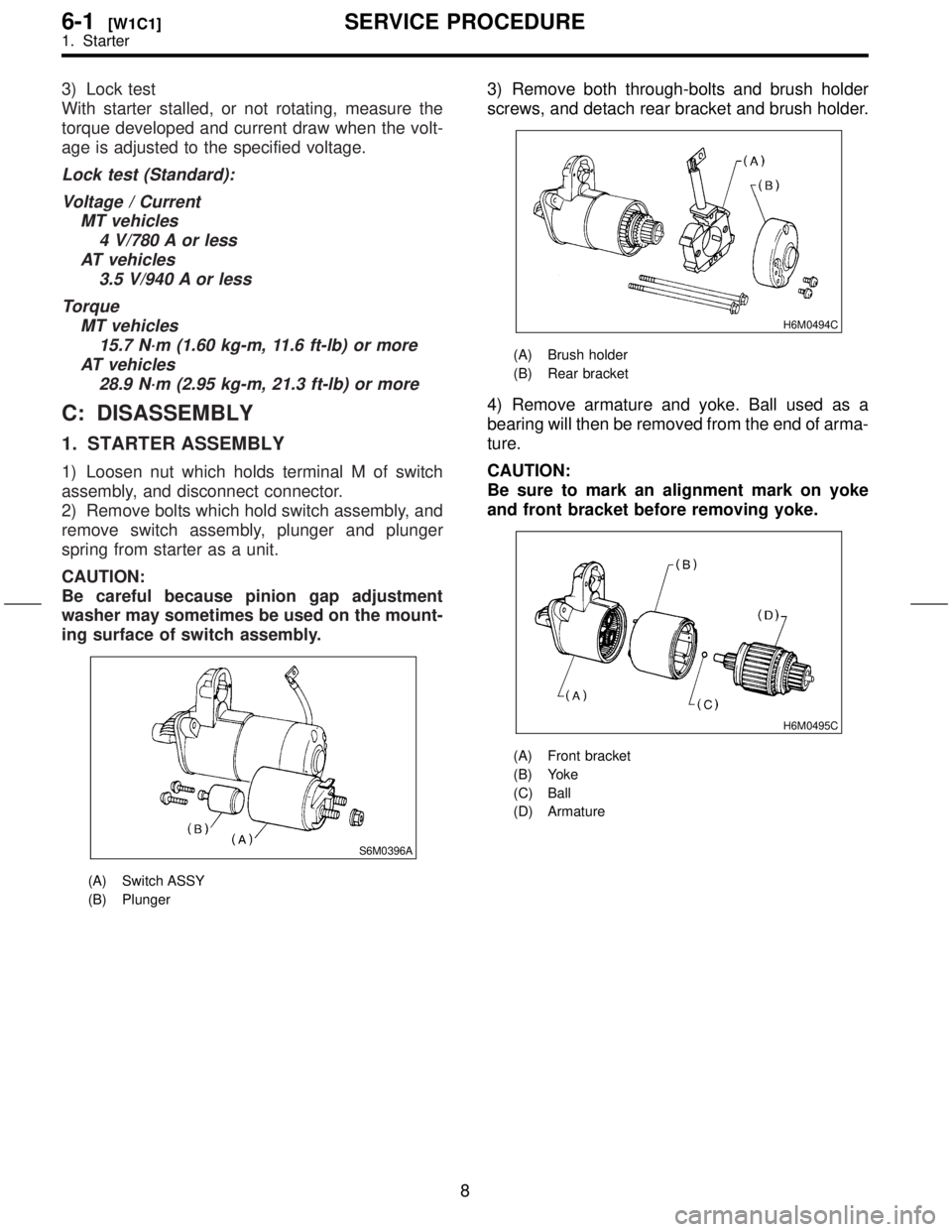
S6M0396A
(A) Switch ASSY
(B) Plunger
3) Remove both through-bolts and brush holder
screws, and detach rear bracket and brush holder.
H6M0494C
(A) Brush holder
(B) Rear bracket
4) Remove armature and yoke. Ball used as a
bearing will then be removed from the end of arma-
ture.
CAUTION:
Be sure to mark an alignment mark on yoke
and front bracket before removing yoke.
H6M0495C
(A) Front bracket
(B) Yoke
(C) Ball
(D) Armature
8
6-1[W1C1]SERVICE PROCEDURE
1. Starter
Page 298 of 345
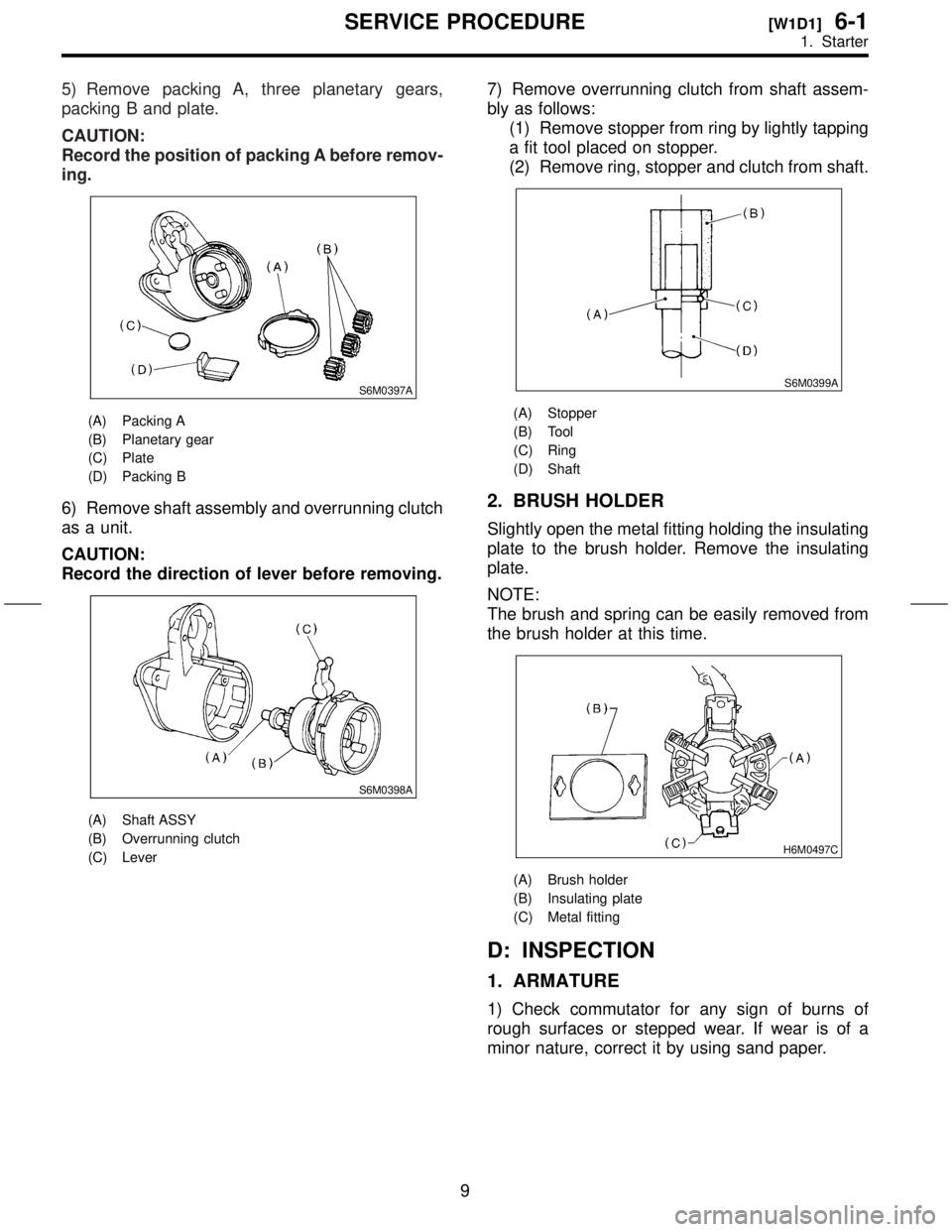
5) Remove packing A, three planetary gears,
packing B and plate.
CAUTION:
Record the position of packing A before remov-
ing.
S6M0397A
(A) Packing A
(B) Planetary gear
(C) Plate
(D) Packing B
6) Remove shaft assembly and overrunning clutch
as a unit.
CAUTION:
Record the direction of lever before removing.
S6M0398A
(A) Shaft ASSY
(B) Overrunning clutch
(C) Lever
7) Remove overrunning clutch from shaft assem-
bly as follows:
(1) Remove stopper from ring by lightly tapping
a fit tool placed on stopper.
(2) Remove ring, stopper and clutch from shaft.
S6M0399A
(A) Stopper
(B) Tool
(C) Ring
(D) Shaft
2. BRUSH HOLDER
Slightly open the metal fitting holding the insulating
plate to the brush holder. Remove the insulating
plate.
NOTE:
The brush and spring can be easily removed from
the brush holder at this time.
H6M0497C
(A) Brush holder
(B) Insulating plate
(C) Metal fitting
D: INSPECTION
1. ARMATURE
1) Check commutator for any sign of burns of
rough surfaces or stepped wear. If wear is of a
minor nature, correct it by using sand paper.
9
[W1D1]6-1SERVICE PROCEDURE
1. Starter
Page 299 of 345
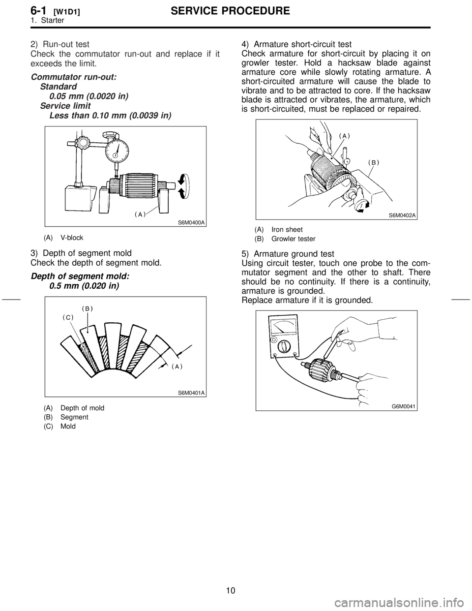
2) Run-out test
Check the commutator run-out and replace if it
exceeds the limit.
Commutator run-out:
Standard
0.05 mm (0.0020 in)
Service limit
Less than 0.10 mm (0.0039 in)
S6M0400A
(A) V-block
3) Depth of segment mold
Check the depth of segment mold.
Depth of segment mold:
0.5 mm (0.020 in)
S6M0401A
(A) Depth of mold
(B) Segment
(C) Mold
4) Armature short-circuit test
Check armature for short-circuit by placing it on
growler tester. Hold a hacksaw blade against
armature core while slowly rotating armature. A
short-circuited armature will cause the blade to
vibrate and to be attracted to core. If the hacksaw
blade is attracted or vibrates, the armature, which
is short-circuited, must be replaced or repaired.
S6M0402A
(A) Iron sheet
(B) Growler tester
5) Armature ground test
Using circuit tester, touch one probe to the com-
mutator segment and the other to shaft. There
should be no continuity. If there is a continuity,
armature is grounded.
Replace armature if it is grounded.
G6M0041
10
6-1[W1D1]SERVICE PROCEDURE
1. Starter
Page 300 of 345
2. YOKE
Make sure pole is set in position.
3. OVERRUNNING CLUTCH
Inspect teeth of pinion for wear and damage.
Replace if it is damaged. Rotate pinion in direction
of rotation (counterclockwise). It should rotate
smoothly. But in opposite direction, it should be
locked.
CAUTION:
Do not clean overrunning clutch with oil to pre-
vent grease from flowing out.
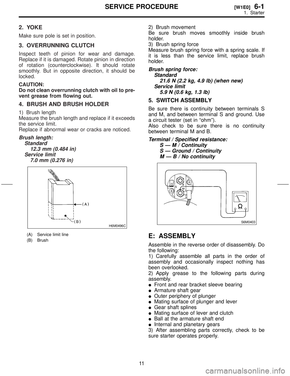
4. BRUSH AND BRUSH HOLDER
1) Brush length
Measure the brush length and replace if it exceeds
the service limit.
Replace if abnormal wear or cracks are noticed.
Brush length:
Standard
12.3 mm (0.484 in)
Service limit
7.0 mm (0.276 in)
H6M0496C
(A) Service limit line
(B) Brush
2) Brush movement
Be sure brush moves smoothly inside brush
holder.
3) Brush spring force
Measure brush spring force with a spring scale. If
it is less than the service limit, replace brush
holder.
Brush spring force:
Standard
21.6 N (2.2 kg, 4.9 lb) (when new)
Service limit
5.9 N (0.6 kg, 1.3 lb)
5. SWITCH ASSEMBLY
Be sure there is continuity between terminals S
and M, and between terminal S and ground. Use
a circuit tester (set in ªohmº).
Also check to be sure there is no continuity
between terminal M and B.
Terminal / Specified resistance:
SÐM/Continuity
S Ð Ground / Continuity
MÐB/Nocontinuity
S6M0403
E: ASSEMBLY
Assemble in the reverse order of disassembly. Do
the following:
1) Carefully assemble all parts in the order of
assembly and occasionally inspect nothing has
been overlooked.
2) Apply grease to the following parts during
assembly.
IFront and rear bracket sleeve bearing
IArmature shaft gear
IOuter periphery of plunger
IMating surface of plunger and lever
IGear shaft splines
IMating surface of lever and clutch
IBall at the armature shaft end
IInternal and planetary gears
3) After assembling parts correctly, check to be
sure starter operates properly.
11
[W1E0]6-1SERVICE PROCEDURE
1. Starter