ECU SUBARU FORESTER 1999 Service Repair Manual
[x] Cancel search | Manufacturer: SUBARU, Model Year: 1999, Model line: FORESTER, Model: SUBARU FORESTER 1999Pages: 345, PDF Size: 5.6 MB
Page 75 of 345
3. Cruise Control System
A: PRECAUTION
1. SUPPLEMENTAL RESTRAINT SYSTEM
ªAIRBAGº
Airbag system wiring harness is routed near the
cruise control module and cruise control command
switch.
CAUTION:
IAll airbag system wiring harness and con-
nectors are yellow. Do not use electrical test
equipment on these circuits.
IBe careful not to damage airbag system wir-
ing harness when servicing the cruise control
module and cruise control command switch.
B: PRE-INSPECTION
1. FUNCTION TESTS
Conduct road tests by selecting a smooth, flat road
or use free rollers for road test simulation.
ICruise Control Main Switch
1) Turn ignition switch to ON.
2) Check that cruise control main switch indicator
light comes on when main switch is pressed (ON).
3) Check that main switch indicator light goes out
when main switch is pressed again (OFF).
4) Turn ignition switch to OFF with main switch ON
(indicated by illumination). Turn ignition switch ON
again to ensure that main switch indicator light
remains OFF.
ICruise Control Command Switch
1) Check that cruise control command switch is
properly set in ªSET/COASTº, ªRESUME/ACCELº,
or ªCANCELº mode.
2) Also check that command switch returns to the
original position when released.
IConstant Speed Test
1) Turn cruise control main switch to ON.
2) Drive the vehicle at a speed greater than 40
km/h (25 MPH).
3) Press command switch to set in ªSET/COASTº
mode.
4) Ensure that vehicle is maintained at the speed
set when command switch was pressed.
IAcceleration Test
1) Set vehicle speed at a speed greater that 40
km/h (25 MPH).
2) Ensure that vehicle continues to accelerate
while holding command switch in ªRESUME/
ACCELº mode, and that vehicle maintains that
optional speed when command switch is released.
IDeceleration Test
1) Set vehicle speed at an optional speed greater
than 40 km/h (25 MPH).
2) Ensure that vehicle continues to decelerate
while holding command switch in ªSET/COASTº
mode, and that it maintains that optional speed
when command switch is released.
NOTE:
When vehicle speed reaches the lower speed limit
of 30 km/h (19 MPH) during deceleration, cruise
control will be released.
2. CRUISE CONTROL CABLE
3B21 : CHECK CRUISE CONTROL CABLE.
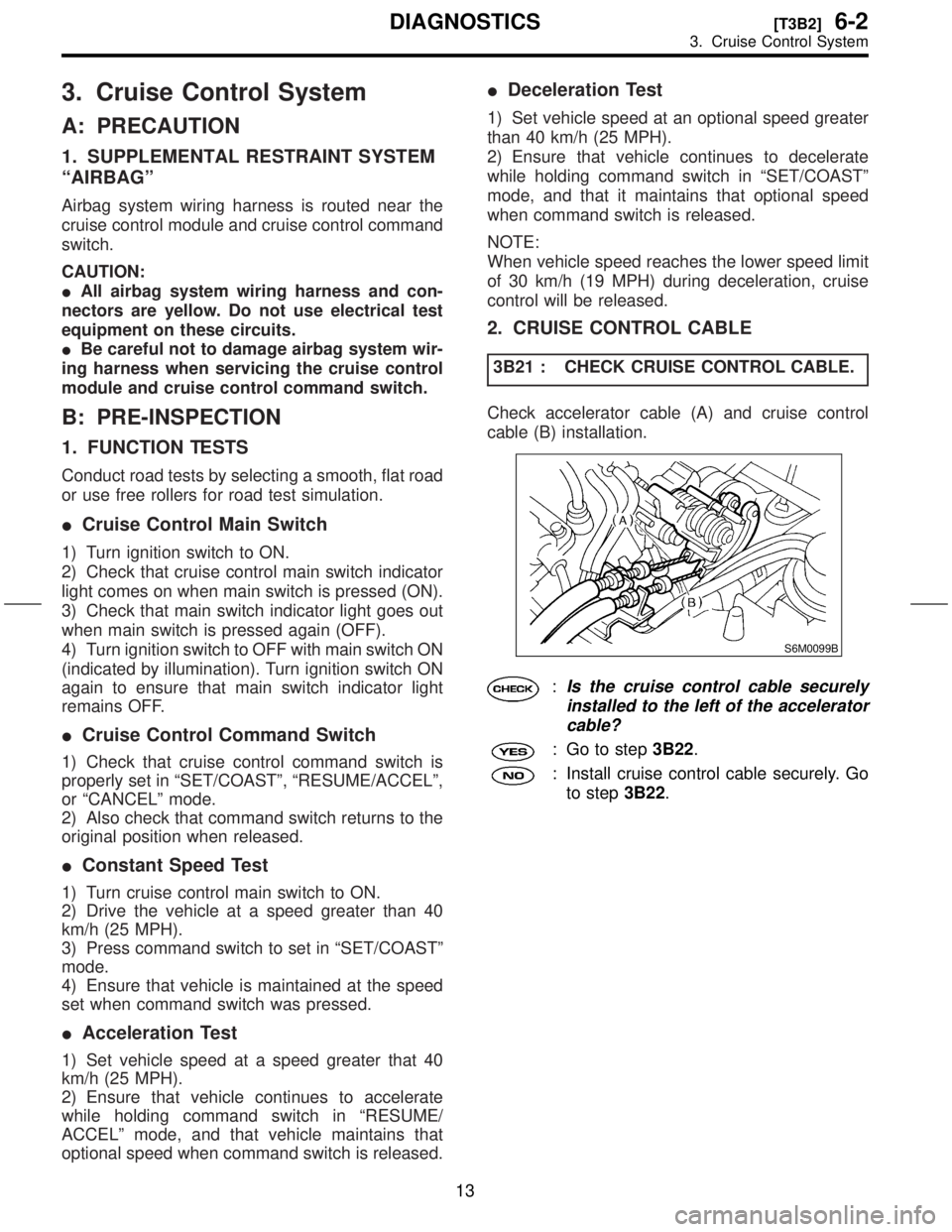
Check accelerator cable (A) and cruise control
cable (B) installation.
S6M0099B
:Is the cruise control cable securely
installed to the left of the accelerator
cable?
: Go to step3B22.
: Install cruise control cable securely. Go
to step3B22.
13
[T3B2]6-2DIAGNOSTICS
3. Cruise Control System
Page 93 of 345
3H21 : CHECK BRAKE SWITCH.
1) Turn ignition switch to ON.
2) Turn cruise control main switch to ON.
3) Apply parking brake securely.
4) Set select monitor in ªCurrent Data Display &
Saveº mode.
5) Depress the brake pedal and check signals for
proper operation.
(1) The Stop Light Switch shown on the display
turns from ªOFFº to ªONº.
(2) The Brake Switch shown on the display
turns from ªOFFº to ªONº.
6) Release the brake pedal.
7) Remove connector of stop and brake switch.
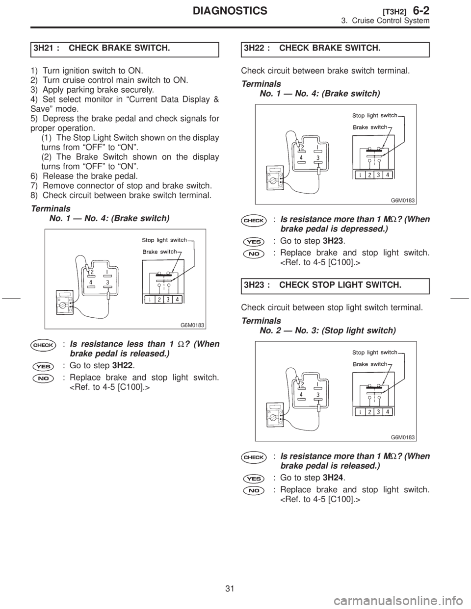
8) Check circuit between brake switch terminal.
Terminals
No. 1 Ð No. 4: (Brake switch)
G6M0183
:Is resistance less than 1W? (When
brake pedal is released.)
: Go to step3H22.
: Replace brake and stop light switch.
Check circuit between brake switch terminal.
Terminals
No. 1 Ð No. 4: (Brake switch)
G6M0183
:Is resistance more than 1 MW? (When
brake pedal is depressed.)
: Go to step3H23.
: Replace brake and stop light switch.
3H23 : CHECK STOP LIGHT SWITCH.
Check circuit between stop light switch terminal.
Terminals
No. 2 Ð No. 3: (Stop light switch)
G6M0183
:Is resistance more than 1 MW? (When
brake pedal is released.)
: Go to step3H24.
: Replace brake and stop light switch.
31
[T3H2]6-2DIAGNOSTICS
3. Cruise Control System
Page 97 of 345
3H31 : CHECK CLUTCH SWITCH. (MT)
1) Turn ignition switch to ON.
2) Turn cruise control main switch to ON.
3) Apply parking brake securely.
4) Set select monitor in ªCurrent Data Display &
Saveº mode.
5) Depress the clutch pedal and check signal for
proper operation. (MT)
The Clutch/Inhibitor Switch shown on the display
turns from ªONº to ªOFFº.
6) Disconnect connector of clutch switch.
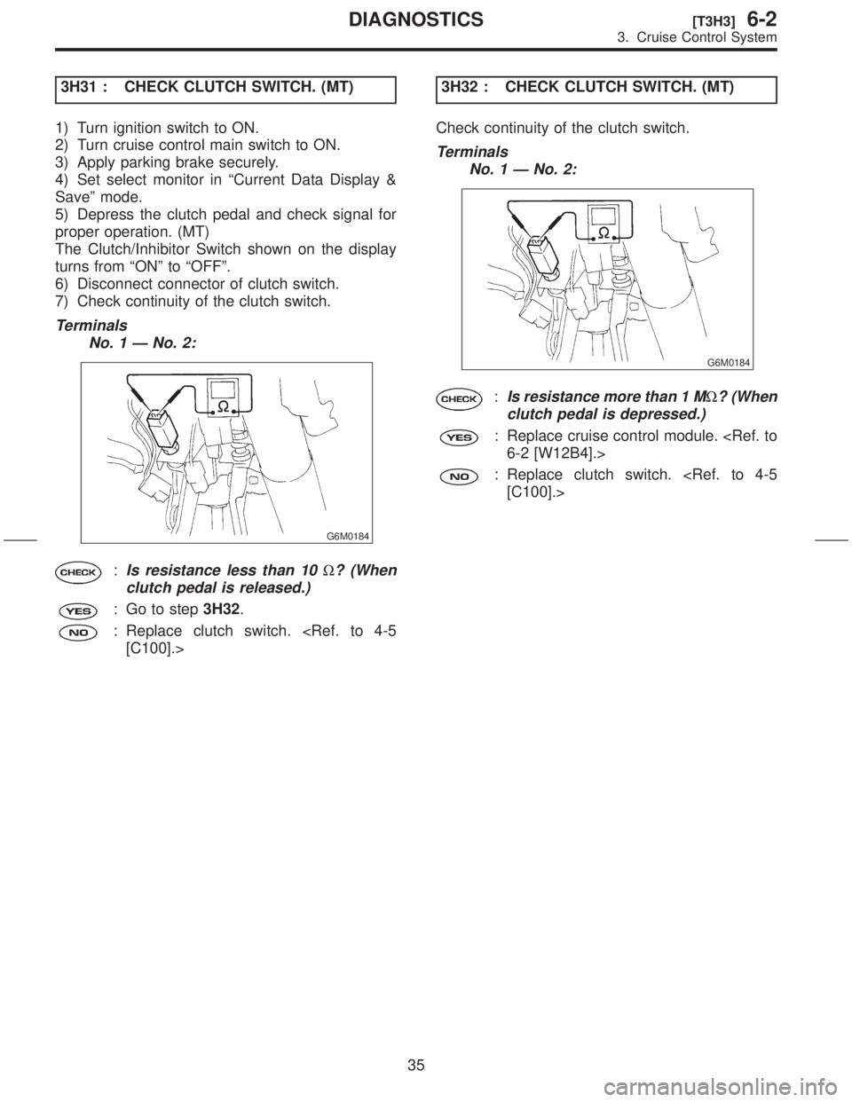
7) Check continuity of the clutch switch.
Terminals
No. 1 Ð No. 2:
G6M0184
:Is resistance less than 10W? (When
clutch pedal is released.)
: Go to step3H32.
: Replace clutch switch.
Check continuity of the clutch switch.
Terminals
No. 1 Ð No. 2:
G6M0184
:Is resistance more than 1 MW? (When
clutch pedal is depressed.)
: Replace cruise control module.
: Replace clutch switch.
35
[T3H3]6-2DIAGNOSTICS
3. Cruise Control System
Page 98 of 345
3H33 : CHECK INHIBITOR SWITCH. (AT)
1) Turn ignition switch to ON.
2) Turn cruise control main switch to ON.
3) Apply parking brake securely.
4) Set select monitor in ªCurrent Data Display &
Saveº mode.
5) Set the select lever from P or N position to D
position and check signal for proper operation.
The Clutch/Inhibitor Switch shown on the display
turns from ªONº to ªOFFº.
6) Set the select lever to P or N position.
7) Disconnect connector of inhibitor switch.
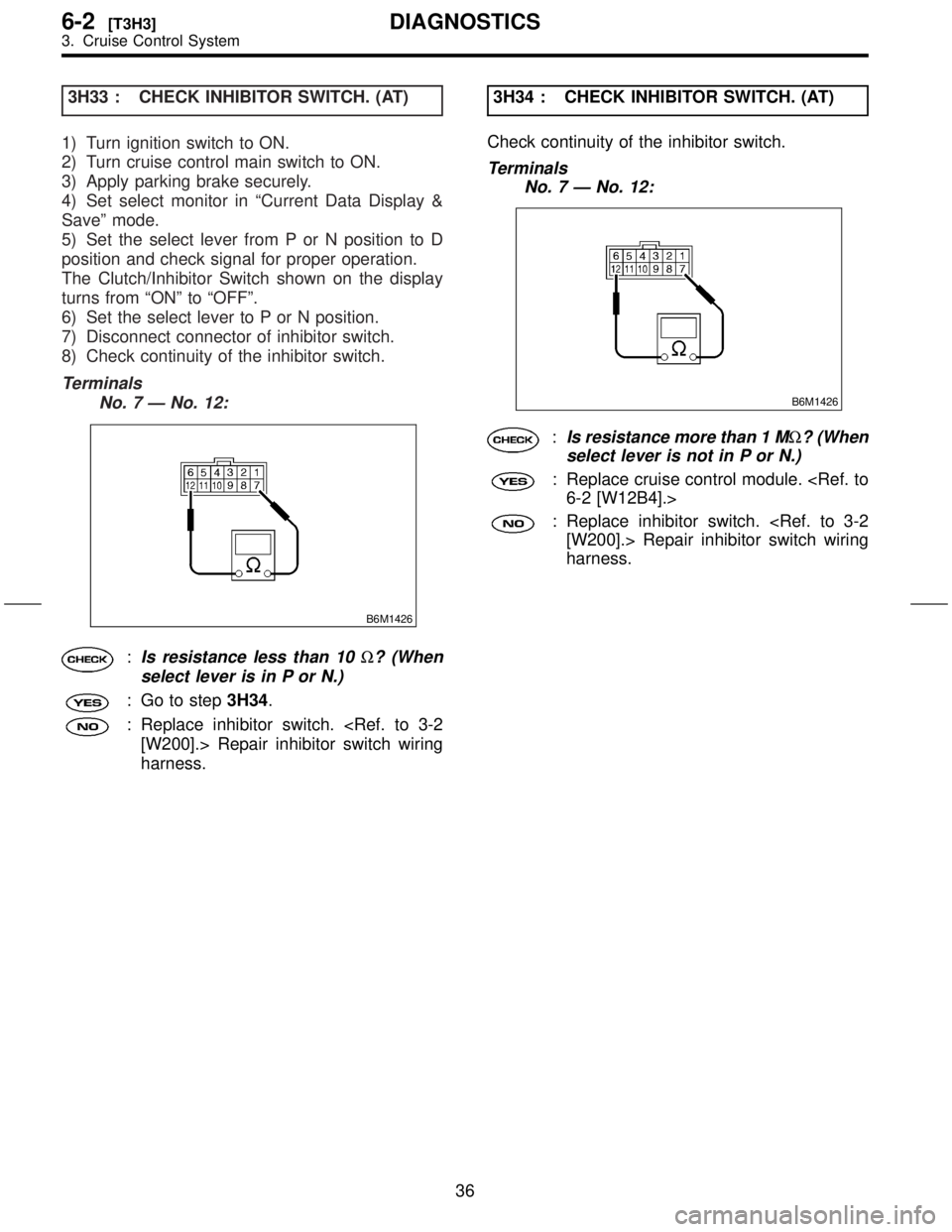
8) Check continuity of the inhibitor switch.
Terminals
No. 7 Ð No. 12:
B6M1426
:Is resistance less than 10W? (When
select lever is in P or N.)
: Go to step3H34.
: Replace inhibitor switch.
harness.3H34 : CHECK INHIBITOR SWITCH. (AT)
Check continuity of the inhibitor switch.
Terminals
No. 7 Ð No. 12:
B6M1426
:Is resistance more than 1 MW? (When
select lever is not in P or N.)
: Replace cruise control module.
: Replace inhibitor switch.
harness.
36
6-2[T3H3]DIAGNOSTICS
3. Cruise Control System
Page 122 of 345
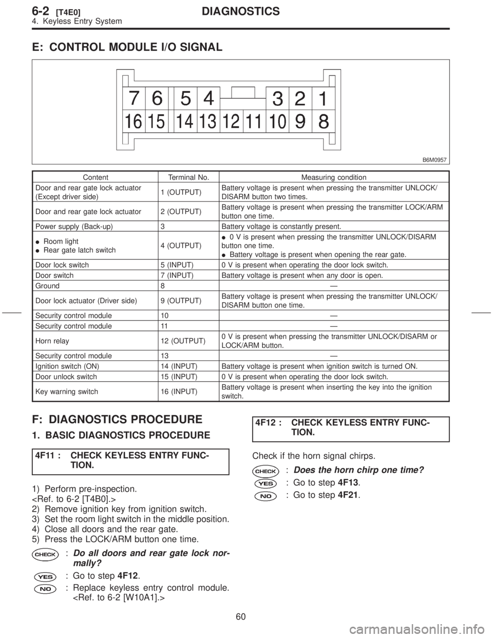
E: CONTROL MODULE I/O SIGNAL
B6M0957
Content Terminal No. Measuring condition
Door and rear gate lock actuator
(Except driver side)1 (OUTPUT)Battery voltage is present when pressing the transmitter UNLOCK/
DISARM button two times.
Door and rear gate lock actuator 2 (OUTPUT)Battery voltage is present when pressing the transmitter LOCK/ARM
button one time.
Power supply (Back-up) 3 Battery voltage is constantly present.
IRoom light
IRear gate latch switch4 (OUTPUT)I0 V is present when pressing the transmitter UNLOCK/DISARM
button one time.
IBattery voltage is present when opening the rear gate.
Door lock switch 5 (INPUT) 0 V is present when operating the door lock switch.
Door switch 7 (INPUT) Battery voltage is present when any door is open.
Ground 8 Ð
Door lock actuator (Driver side) 9 (OUTPUT)Battery voltage is present when pressing the transmitter UNLOCK/
DISARM button one time.
Security control module 10 Ð
Security control module 11 Ð
Horn relay 12 (OUTPUT)0 V is present when pressing the transmitter UNLOCK/DISARM or
LOCK/ARM button.
Security control module 13 Ð
Ignition switch (ON) 14 (INPUT) Battery voltage is present when ignition switch is turned ON.
Door unlock switch 15 (INPUT) 0 V is present when operating the door lock switch.
Key warning switch 16 (INPUT)Battery voltage is present when inserting the key into the ignition
switch.
F: DIAGNOSTICS PROCEDURE
1. BASIC DIAGNOSTICS PROCEDURE
4F11 : CHECK KEYLESS ENTRY FUNC-
TION.
1) Perform pre-inspection.
2) Remove ignition key from ignition switch.
3) Set the room light switch in the middle position.
4) Close all doors and the rear gate.
5) Press the LOCK/ARM button one time.
:Do all doors and rear gate lock nor-
mally?
: Go to step4F12.
: Replace keyless entry control module.
TION.
Check if the horn signal chirps.
:Does the horn chirp one time?
: Go to step4F13.
: Go to step4F21.
60
6-2[T4E0]DIAGNOSTICS
4. Keyless Entry System
Page 131 of 345
5. Security System
A: PRECAUTION
1. SUPPLEMENTAL RESTRAINT SYSTEM
ªAIRBAGº
Airbag system wiring harness is routed near the
security control module.
CAUTION:
IAll airbag system wiring harness and con-
nectors are yellow. Do not use electrical test
equipment on these circuits.
IBe careful not to damage airbag system wir-
ing harness when servicing the security con-
trol module.
B: PRE-INSPECTION
1. FUSE
5B11 : CHECK FUSE.
Remove and visually check the fuse No. 7 (in main
fuse box).
:Is fuse No. 7 blown?
: Replace fuse (20 A).
: Go to step5B12.
5B12 : CHECK FUSE.
Remove and visually check the fuse No. 2 (in main
fuse box).
:Is fuse No. 2 blown?
: Replace fuse (15 A).
: Go to step5B21.
2. POWER SUPPLY CIRCUIT
5B21 : CHECK POWER SUPPLY CIRCUIT.
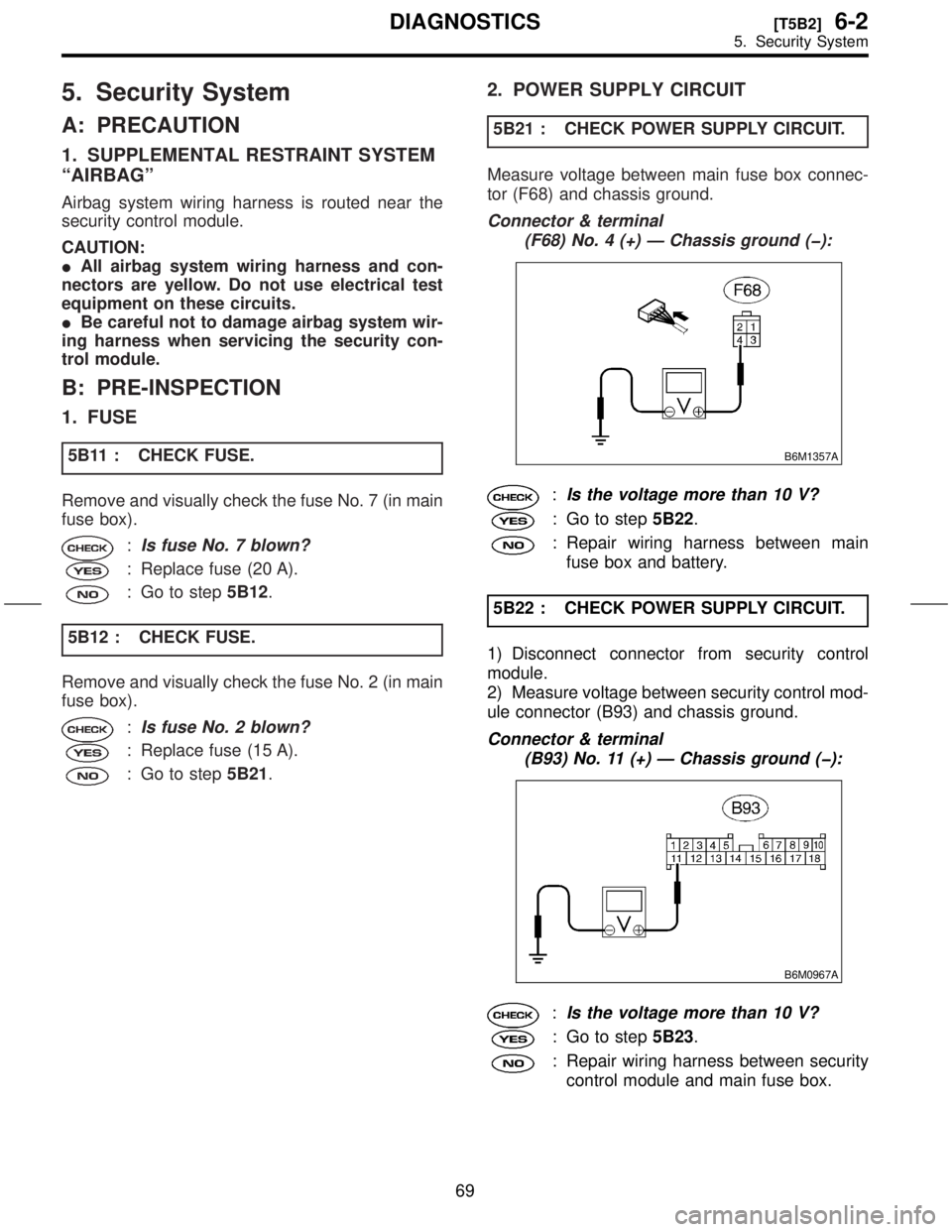
Measure voltage between main fuse box connec-
tor (F68) and chassis ground.
Connector & terminal
(F68) No. 4 (+) Ð Chassis ground (þ):
B6M1357A
:Is the voltage more than 10 V?
: Go to step5B22.
: Repair wiring harness between main
fuse box and battery.
5B22 : CHECK POWER SUPPLY CIRCUIT.
1) Disconnect connector from security control
module.
2) Measure voltage between security control mod-
ule connector (B93) and chassis ground.
Connector & terminal
(B93) No. 11 (+) Ð Chassis ground (þ):
B6M0967A
:Is the voltage more than 10 V?
: Go to step5B23.
: Repair wiring harness between security
control module and main fuse box.
69
[T5B2]6-2DIAGNOSTICS
5. Security System
Page 132 of 345

5B23 : CHECK POWER SUPPLY CIRCUIT.
Measure voltage between main fuse box connec-
tor (F68) and chassis ground.
Connector & terminal
(F68) No. 2 (+) Ð Chassis ground (þ):
B6M1358A
:Is the voltage more than 10 V?
: Go to step5B24.
: Repair wiring harness between main
fuse box and battery.
5B24 : CHECK POWER SUPPLY CIRCUIT.
Measure voltage between security control module
connector (B93) and chassis ground.
Connector & terminal
(B93) No. 13 (+) Ð Chassis ground (þ):
B6M0968A
:Is the voltage more than 10 V?
: Go to step5B31.
: Repair wiring harness between security
control module and main fuse box.
3. GROUND CIRCUIT
5B31 : CHECK GROUND CIRCUIT.
Measure resistance between security control mod-
ule connector (B93) and chassis ground.
Connector & terminal
(B93) No. 14 (+) Ð Chassis ground:
B6M0969A
:Is the resistance less than 10W?
: Go to step5F11.
: Repair wiring harness between security
control module and chassis ground.
70
6-2[T5B2]DIAGNOSTICS
5. Security System
Page 133 of 345

C: ELECTRICAL COMPONENTS LOCATION
S6M0454A
(1) Horn
(2) Keyless entry control module
(3) Security control module (under
console box)
(4) Security indicator light (in combi-
nation meter)(5) Horn relay (in main fuse box)
(6) Rear gate latch switch
(7) Interrupt relay (behind the fuse
box)
(8) Door switch(9) Passive arm connector (on driver
side front lower pillar)
71
[T5C0]6-2DIAGNOSTICS
5. Security System
Page 134 of 345
![SUBARU FORESTER 1999 Service Repair Manual D: SCHEMATIC
s6m0455
S6M0455
72
6-2[T5D0]DIAGNOSTICS
5. Security System SUBARU FORESTER 1999 Service Repair Manual D: SCHEMATIC
s6m0455
S6M0455
72
6-2[T5D0]DIAGNOSTICS
5. Security System](/img/17/57427/w960_57427-133.png)
D: SCHEMATIC
s6m0455
S6M0455
72
6-2[T5D0]DIAGNOSTICS
5. Security System
Page 135 of 345
![SUBARU FORESTER 1999 Service Repair Manual s6m0456
S6M0456
73
[T5D0]6-2DIAGNOSTICS
5. Security System SUBARU FORESTER 1999 Service Repair Manual s6m0456
S6M0456
73
[T5D0]6-2DIAGNOSTICS
5. Security System](/img/17/57427/w960_57427-134.png)
s6m0456
S6M0456
73
[T5D0]6-2DIAGNOSTICS
5. Security System