air condition SUBARU FORESTER 1999 Service Repair Manual
[x] Cancel search | Manufacturer: SUBARU, Model Year: 1999, Model line: FORESTER, Model: SUBARU FORESTER 1999Pages: 345, PDF Size: 5.6 MB
Page 10 of 345
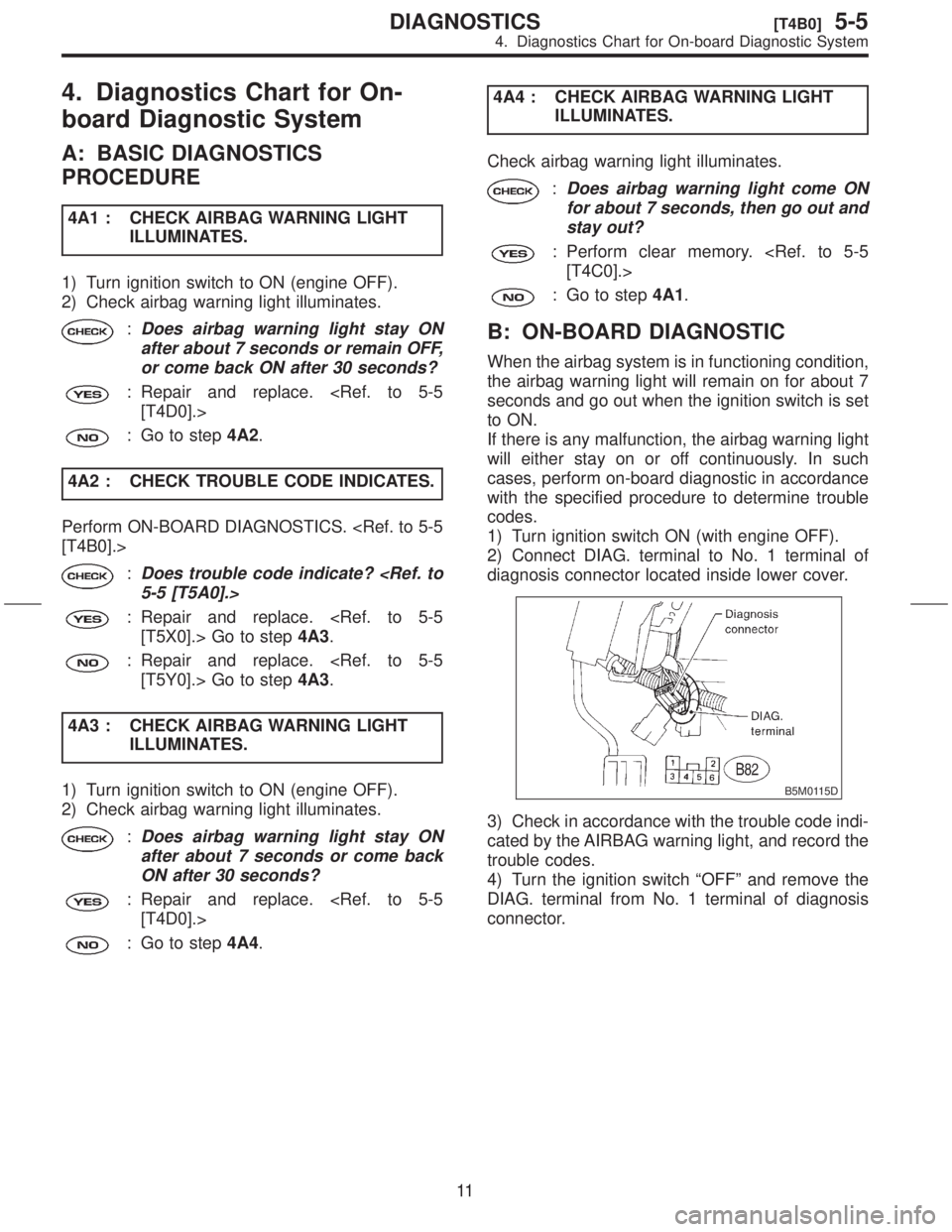
4. Diagnostics Chart for On-
board Diagnostic System
A: BASIC DIAGNOSTICS
PROCEDURE
4A1 : CHECK AIRBAG WARNING LIGHT
ILLUMINATES.
1) Turn ignition switch to ON (engine OFF).
2) Check airbag warning light illuminates.
:Does airbag warning light stay ON
after about 7 seconds or remain OFF,
or come back ON after 30 seconds?
: Repair and replace.
: Go to step4A2.
4A2 : CHECK TROUBLE CODE INDICATES.
Perform ON-BOARD DIAGNOSTICS.
:Does trouble code indicate?
: Repair and replace.
: Repair and replace.
4A3 : CHECK AIRBAG WARNING LIGHT
ILLUMINATES.
1) Turn ignition switch to ON (engine OFF).
2) Check airbag warning light illuminates.
:Does airbag warning light stay ON
after about 7 seconds or come back
ON after 30 seconds?
: Repair and replace.
: Go to step4A4.4A4 : CHECK AIRBAG WARNING LIGHT
ILLUMINATES.
Check airbag warning light illuminates.
:Does airbag warning light come ON
for about 7 seconds, then go out and
stay out?
: Perform clear memory.
: Go to step4A1.
B: ON-BOARD DIAGNOSTIC
When the airbag system is in functioning condition,
the airbag warning light will remain on for about 7
seconds and go out when the ignition switch is set
to ON.
If there is any malfunction, the airbag warning light
will either stay on or off continuously. In such
cases, perform on-board diagnostic in accordance
with the specified procedure to determine trouble
codes.
1) Turn ignition switch ON (with engine OFF).
2) Connect DIAG. terminal to No. 1 terminal of
diagnosis connector located inside lower cover.
B5M0115D
3) Check in accordance with the trouble code indi-
cated by the AIRBAG warning light, and record the
trouble codes.
4) Turn the ignition switch ªOFFº and remove the
DIAG. terminal from No. 1 terminal of diagnosis
connector.
11
[T4B0]5-5DIAGNOSTICS
4. Diagnostics Chart for On-board Diagnostic System
Page 79 of 345
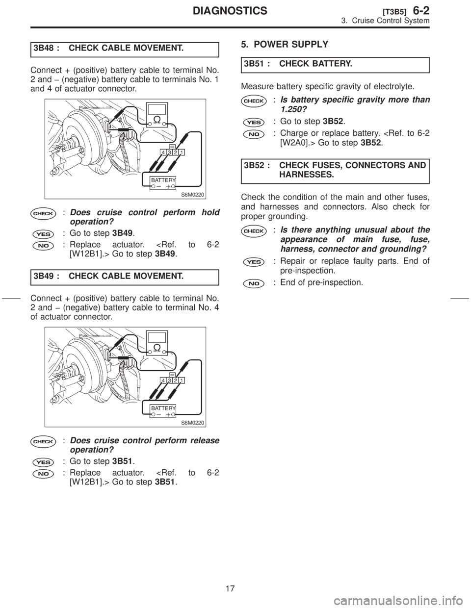
3B48 : CHECK CABLE MOVEMENT.
Connect + (positive) battery cable to terminal No.
2 and þ (negative) battery cable to terminals No. 1
and 4 of actuator connector.
S6M0220
:Does cruise control perform hold
operation?
: Go to step3B49.
: Replace actuator.
3B49 : CHECK CABLE MOVEMENT.
Connect + (positive) battery cable to terminal No.
2 and þ (negative) battery cable to terminal No. 4
of actuator connector.
S6M0220
:Does cruise control perform release
operation?
: Go to step3B51.
: Replace actuator.
5. POWER SUPPLY
3B51 : CHECK BATTERY.
Measure battery specific gravity of electrolyte.
:Is battery specific gravity more than
1.250?
: Go to step3B52.
: Charge or replace battery.
3B52 : CHECK FUSES, CONNECTORS AND
HARNESSES.
Check the condition of the main and other fuses,
and harnesses and connectors. Also check for
proper grounding.
:Is there anything unusual about the
appearance of main fuse, fuse,
harness, connector and grounding?
: Repair or replace faulty parts. End of
pre-inspection.
: End of pre-inspection.
17
[T3B5]6-2DIAGNOSTICS
3. Cruise Control System
Page 192 of 345
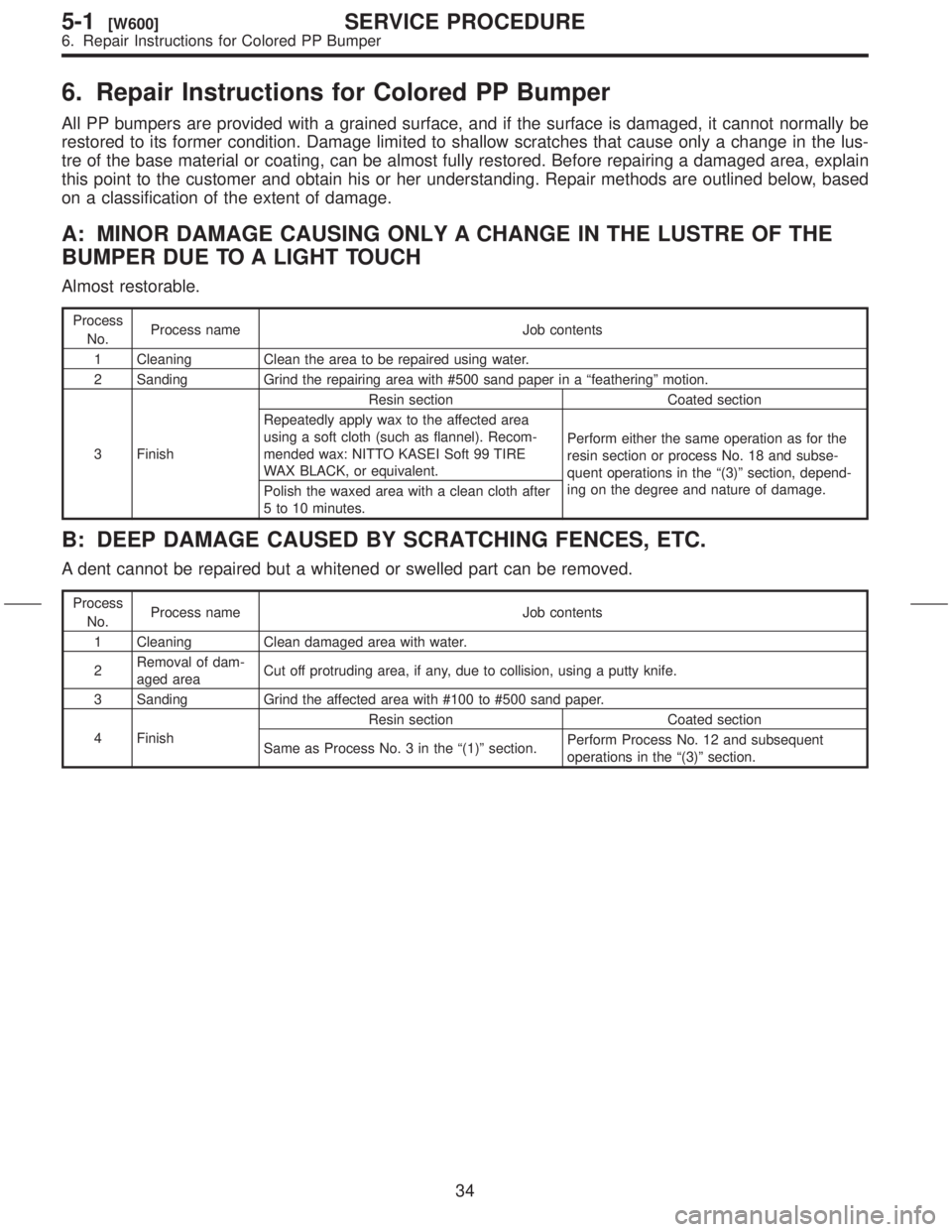
6. Repair Instructions for Colored PP Bumper
All PP bumpers are provided with a grained surface, and if the surface is damaged, it cannot normally be
restored to its former condition. Damage limited to shallow scratches that cause only a change in the lus-
tre of the base material or coating, can be almost fully restored. Before repairing a damaged area, explain
this point to the customer and obtain his or her understanding. Repair methods are outlined below, based
on a classification of the extent of damage.
A: MINOR DAMAGE CAUSING ONLY A CHANGE IN THE LUSTRE OF THE
BUMPER DUE TO A LIGHT TOUCH
Almost restorable.
Process
No.Process name Job contents
1 Cleaning Clean the area to be repaired using water.
2 Sanding Grind the repairing area with #500 sand paper in a ªfeatheringº motion.
3 FinishResin section Coated section
Repeatedly apply wax to the affected area
using a soft cloth (such as flannel). Recom-
mended wax: NITTO KASEI Soft 99 TIRE
WAX BLACK, or equivalent.Perform either the same operation as for the
resin section or process No. 18 and subse-
quent operations in the ª(3)º section, depend-
ing on the degree and nature of damage.
Polish the waxed area with a clean cloth after
5 to 10 minutes.
B: DEEP DAMAGE CAUSED BY SCRATCHING FENCES, ETC.
A dent cannot be repaired but a whitened or swelled part can be removed.
Process
No.Process name Job contents
1 Cleaning Clean damaged area with water.
2Removal of dam-
aged areaCut off protruding area, if any, due to collision, using a putty knife.
3 Sanding Grind the affected area with #100 to #500 sand paper.
4 FinishResin section Coated section
Same as Process No. 3 in the ª(1)º section.Perform Process No. 12 and subsequent
operations in the ª(3)º section.
34
5-1[W600]SERVICE PROCEDURE
6. Repair Instructions for Colored PP Bumper
Page 195 of 345
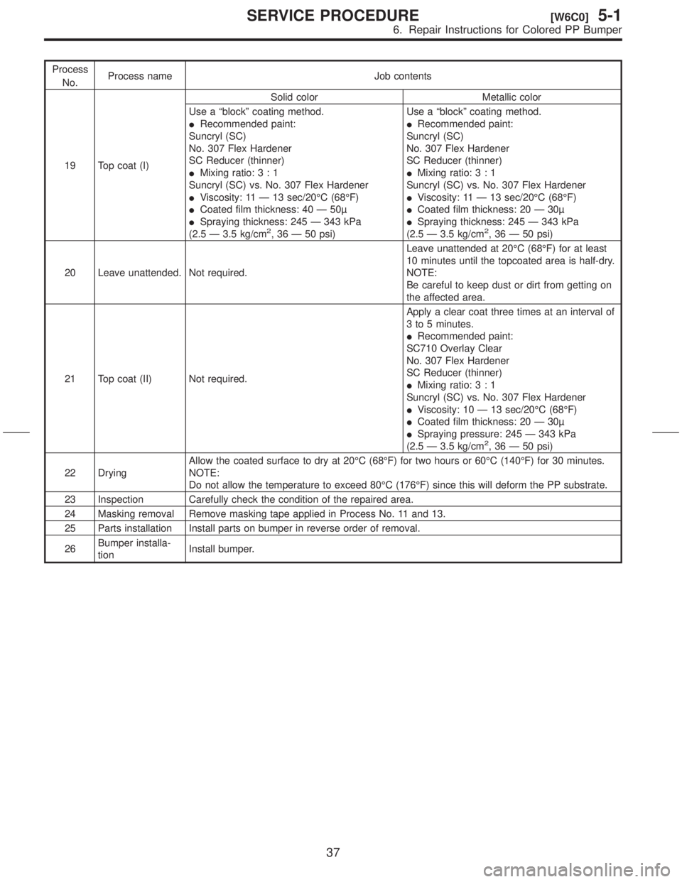
Process
No.Process name Job contents
19 Top coat (I)Solid color Metallic color
Use a ªblockº coating method.
IRecommended paint:
Suncryl (SC)
No. 307 Flex Hardener
SC Reducer (thinner)
IMixing ratio:3:1
Suncryl (SC) vs. No. 307 Flex Hardener
IViscosity: 11 Ð 13 sec/20ÉC (68ÉF)
ICoated film thickness: 40 Ð 50
ISpraying thickness: 245 Ð 343 kPa
(2.5 Ð 3.5 kg/cm
2, 36 Ð 50 psi)Use a ªblockº coating method.
IRecommended paint:
Suncryl (SC)
No. 307 Flex Hardener
SC Reducer (thinner)
IMixing ratio:3:1
Suncryl (SC) vs. No. 307 Flex Hardener
IViscosity: 11 Ð 13 sec/20ÉC (68ÉF)
ICoated film thickness: 20 Ð 30
ISpraying thickness: 245 Ð 343 kPa
(2.5 Ð 3.5 kg/cm2, 36 Ð 50 psi)
20 Leave unattended. Not required.Leave unattended at 20ÉC (68ÉF) for at least
10 minutes until the topcoated area is half-dry.
NOTE:
Be careful to keep dust or dirt from getting on
the affected area.
21 Top coat (II) Not required.Apply a clear coat three times at an interval of
3 to 5 minutes.
IRecommended paint:
SC710 Overlay Clear
No. 307 Flex Hardener
SC Reducer (thinner)
IMixing ratio:3:1
Suncryl (SC) vs. No. 307 Flex Hardener
IViscosity: 10 Ð 13 sec/20ÉC (68ÉF)
ICoated film thickness: 20 Ð 30
ISpraying pressure: 245 Ð 343 kPa
(2.5 Ð 3.5 kg/cm
2, 36 Ð 50 psi)
22 DryingAllow the coated surface to dry at 20ÉC (68ÉF) for two hours or 60ÉC (140ÉF) for 30 minutes.
NOTE:
Do not allow the temperature to exceed 80ÉC (176ÉF) since this will deform the PP substrate.
23 Inspection Carefully check the condition of the repaired area.
24 Masking removal Remove masking tape applied in Process No. 11 and 13.
25 Parts installation Install parts on bumper in reverse order of removal.
26Bumper installa-
tionInstall bumper.
37
[W6C0]5-1SERVICE PROCEDURE
6. Repair Instructions for Colored PP Bumper
Page 278 of 345
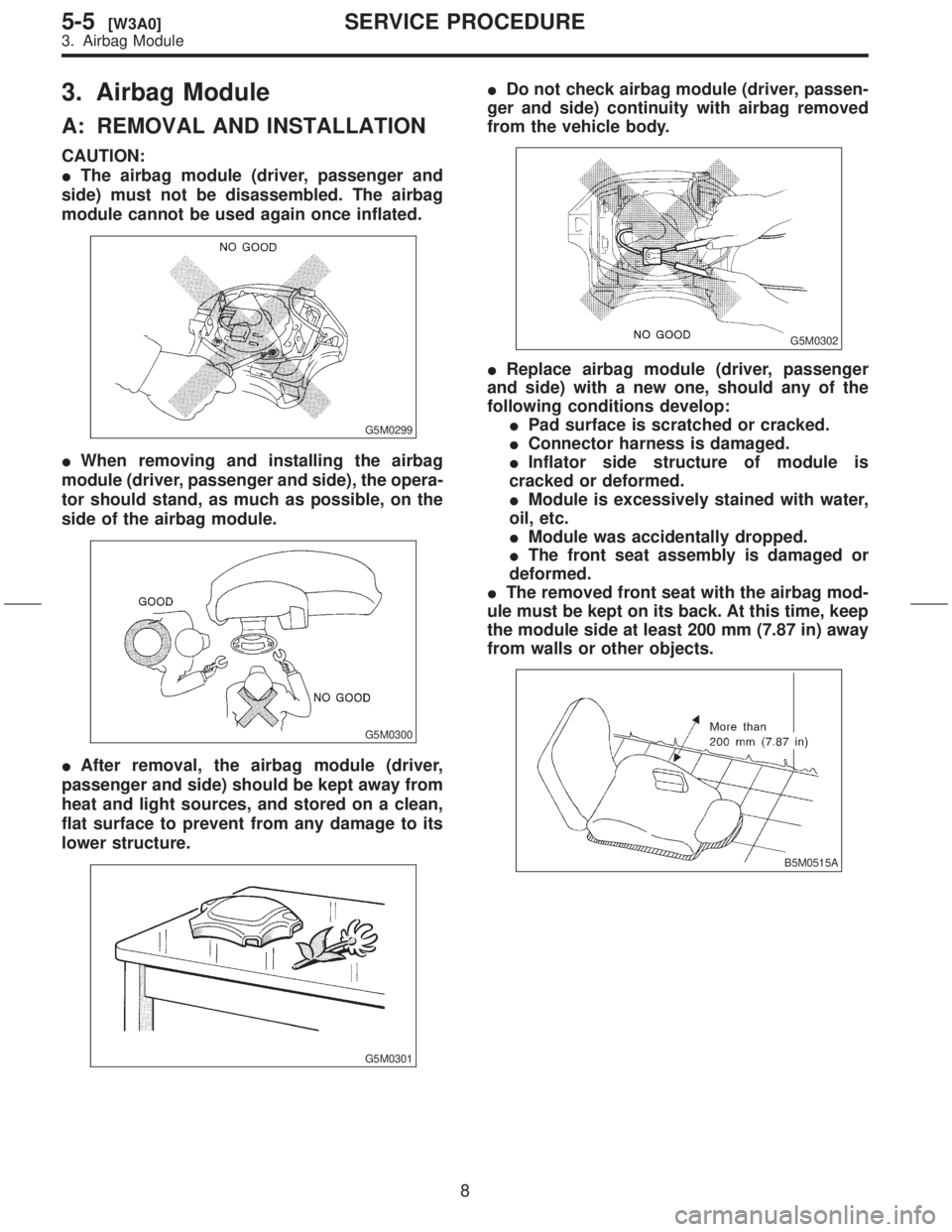
3. Airbag Module
A: REMOVAL AND INSTALLATION
CAUTION:
IThe airbag module (driver, passenger and
side) must not be disassembled. The airbag
module cannot be used again once inflated.
G5M0299
IWhen removing and installing the airbag
module (driver, passenger and side), the opera-
tor should stand, as much as possible, on the
side of the airbag module.
G5M0300
IAfter removal, the airbag module (driver,
passenger and side) should be kept away from
heat and light sources, and stored on a clean,
flat surface to prevent from any damage to its
lower structure.
G5M0301
IDo not check airbag module (driver, passen-
ger and side) continuity with airbag removed
from the vehicle body.
G5M0302
IReplace airbag module (driver, passenger
and side) with a new one, should any of the
following conditions develop:
IPad surface is scratched or cracked.
IConnector harness is damaged.
IInflator side structure of module is
cracked or deformed.
IModule is excessively stained with water,
oil, etc.
IModule was accidentally dropped.
IThe front seat assembly is damaged or
deformed.
IThe removed front seat with the airbag mod-
ule must be kept on its back. At this time, keep
the module side at least 200 mm (7.87 in) away
from walls or other objects.
B5M0515A
8
5-5[W3A0]SERVICE PROCEDURE
3. Airbag Module
Page 279 of 345
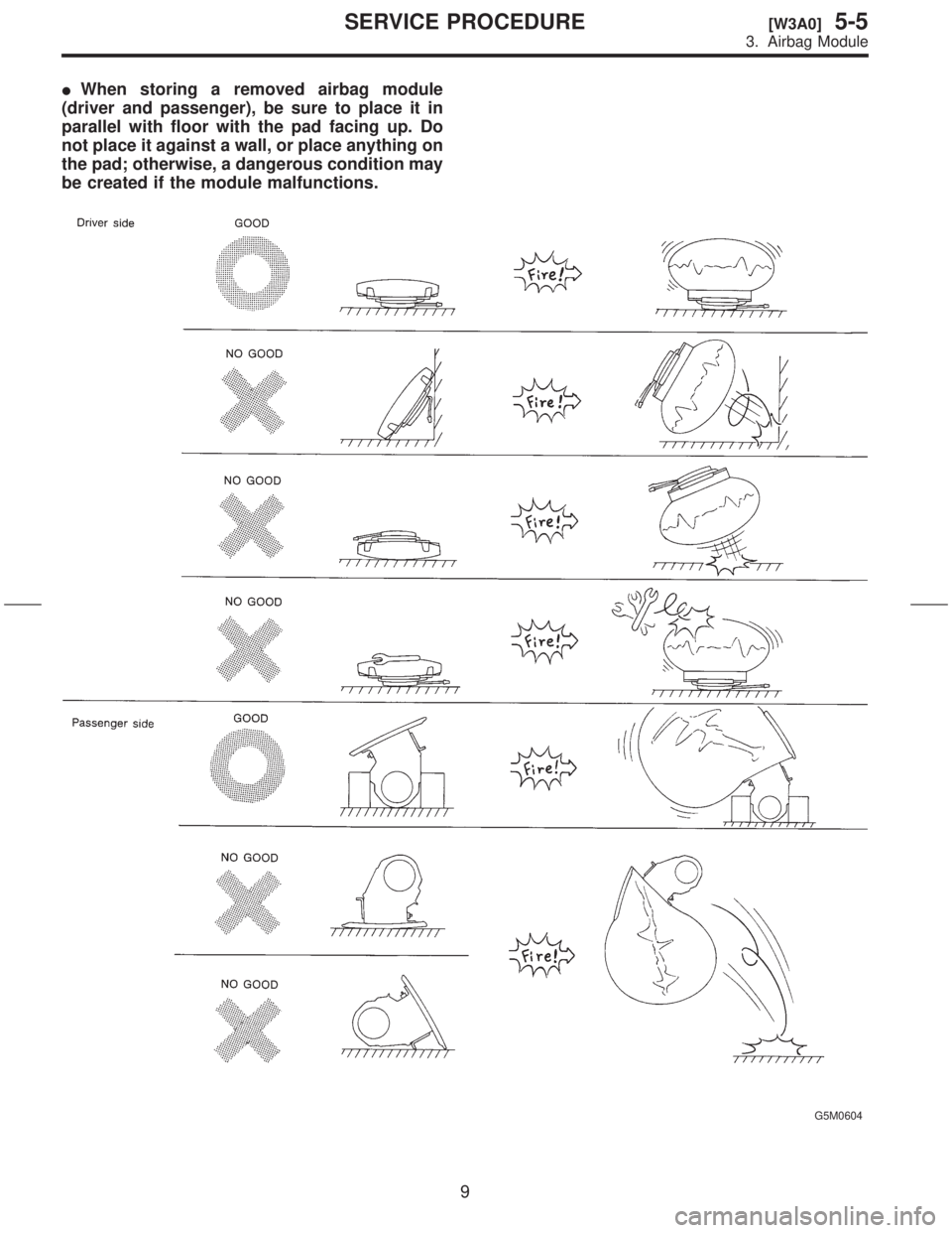
IWhen storing a removed airbag module
(driver and passenger), be sure to place it in
parallel with floor with the pad facing up. Do
not place it against a wall, or place anything on
the pad; otherwise, a dangerous condition may
be created if the module malfunctions.
G5M0604
9
[W3A0]5-5SERVICE PROCEDURE
3. Airbag Module
Page 303 of 345

1) Checking positive diode
Check for continuity between the diode lead and
the positive side heat sink. The positive diode is in
good condition if continuity exists only in the direc-
tion from the diode lead to the heat sink.
S6M0406A
(A) Diode lead
(B) Heat sink (Positive side)
2) Checking negative diode
Check for continuity between the negative side
heat sink and diode lead. The negative diode is in
good condition if continuity exists only in the direc-
tion from the heat sink to the diode lead.
S6M0407A
(A) Diode lead
(B) Heat sink (Negative side)
2. ROTOR
1) Slip ring surface
Inspect slip rings for contamination or any rough-
ness of the sliding surface. Repair slip ring surface
using a lathe or sand paper.
2) Slip ring outer diameter
Measure slip ring outer diameter. If slip ring is worn
replace rotor assembly.
Slip ring outer diameter:
Standard
22.7 mm (0.894 in)
Limit
22.1 mm (0.870 in)
3) Continuity test
Check resistance between slip rings using circuit
tester.
If the resistance is not within specification, replace
rotor assembly.
Specified resistance:
Approx. 2.7 Ð 3.2
W
G6M0075
4) Insulation test
Check continuity between slip ring and rotor core
or shaft. If continuity exists, the rotor coil is
grounded, and so replace rotor assembly.
G6M0076
5) Ball bearing (rear side)
(1) Check rear ball bearing. Replace if it is
noisy or if rotor does not turn smoothly.
(2) The rear bearing can be removed by using
common bearing puller.
G6M0077
14
6-1[W2C2]SERVICE PROCEDURE
2. Generator
Page 310 of 345
7) Install in the reverse order of removal.
Tightening torque (Spark plug):
20.6
±2.9 N´m (2.10±0.30 kg-m, 15.19±2.14
ft-lb)
CAUTION:
The above torque should be only applied to
new spark plugs without oil on their threads.
In case their threads are lubricated, the torque
should be reduced by approximately 1/3 of the
specified torque in order to avoid over-stress-
ing.
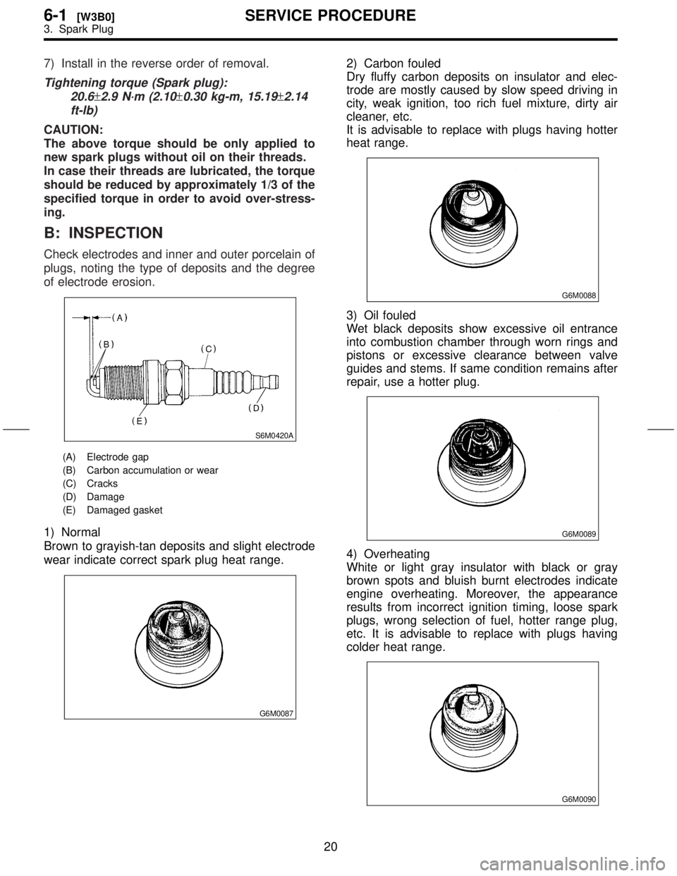
B: INSPECTION
Check electrodes and inner and outer porcelain of
plugs, noting the type of deposits and the degree
of electrode erosion.
S6M0420A
(A) Electrode gap
(B) Carbon accumulation or wear
(C) Cracks
(D) Damage
(E) Damaged gasket
1) Normal
Brown to grayish-tan deposits and slight electrode
wear indicate correct spark plug heat range.
G6M0087
2) Carbon fouled
Dry fluffy carbon deposits on insulator and elec-
trode are mostly caused by slow speed driving in
city, weak ignition, too rich fuel mixture, dirty air
cleaner, etc.
It is advisable to replace with plugs having hotter
heat range.
G6M0088
3) Oil fouled
Wet black deposits show excessive oil entrance
into combustion chamber through worn rings and
pistons or excessive clearance between valve
guides and stems. If same condition remains after
repair, use a hotter plug.
G6M0089
4) Overheating
White or light gray insulator with black or gray
brown spots and bluish burnt electrodes indicate
engine overheating. Moreover, the appearance
results from incorrect ignition timing, loose spark
plugs, wrong selection of fuel, hotter range plug,
etc. It is advisable to replace with plugs having
colder heat range.
G6M0090
20
6-1[W3B0]SERVICE PROCEDURE
3. Spark Plug