air pressure switch SUBARU FORESTER 2004 Service User Guide
[x] Cancel search | Manufacturer: SUBARU, Model Year: 2004, Model line: FORESTER, Model: SUBARU FORESTER 2004Pages: 2870, PDF Size: 38.67 MB
Page 64 of 2870

AC-8
HVAC SYSTEM (AUTO A/C)(DIAGNOSTIC)
Auto A/C Control Module I/O Signal
*1: Battery voltage is indicated when motor running, 0 V or battery voltage pulse signal is output when motor stops.
*2: Battery voltage is indicated when motor running, 0 V is indicated when motor stops.
*3: Voltage can not be measured because of pulse signal.
B: WIRING DIAGRAM:
A14Combination meter (ambient temperature sig-
nal)*3 *3
A13 Mode door actuator position detection signal OutletVENT, BI-LEVEL, HEAT 5 V
DEF/HEAT, DEF 0 V
A12 Mode door actuator position detection signal OutletVENT, DEF/HEAT 5 V
BI-LEVEL, HEAT, DEF 0 V
A10 A/C cutout signalA/C: ON Battery voltage
Pressure switch operated 0 V
A9 Illumination ground When there is continuity to chassis ground 0 Ω Terminal No. Content Measuring conditionSpecified
value
Page 72 of 2870
AC-16
HVAC SYSTEM (AUTO A/C)(DIAGNOSTIC)
Diagnostics for A/C System Malfunction
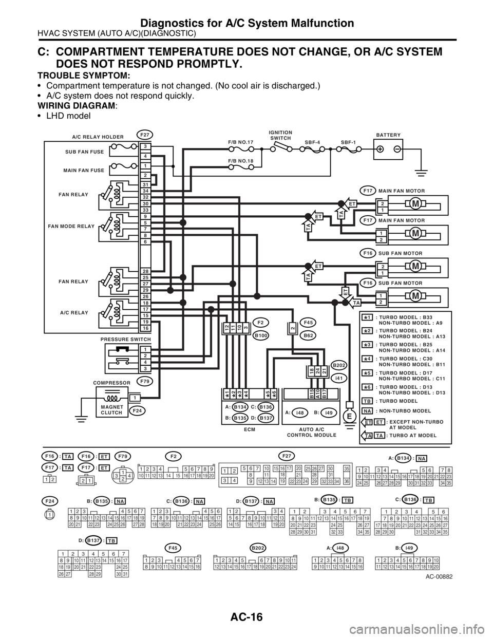
C: COMPARTMENT TEMPERATURE DOES NOT CHANGE, OR A/C SYSTEM
DOES NOT RESPOND PROMPTLY.
TROUBLE SYMPTOM:
Compartment temperature is not changed. (No cool air is discharged.)
A/C system does not respond quickly.
WIRING DIAGRAM:
LHD model
AC-00882
A: B134 :
B: B135 :
B202
D: B137 :C: B136 :
F2F27
EA:
i48
F27
F17
F79
F45
B62
B202
i41
F24
F24
F16F79
F45
F17
B:
i49A:
B134 B136
B135 B137C:
B:D:IGNITION
SWITCHBATTERY
A/C RELAY HOLDER
FAN RELAY
FAN RELAY
A/C RELAY
PRESSURE SWITCH
COMPRESSOR
MAGNET
CLUTCH FAN MODE RELAYSUB FAN FUSE
MAIN FAN FUSE
MAIN FAN MOTOR
1
M
SBF-1SBF-4F/B NO.17
F/B NO.18
1
2
3
2
1
4
3033
32 31
34
86
7 9
5
2926
27 28
25
1916
15 18
17
43
21
B15A10B17
F17
MAIN FAN MOTOR
M
F16
SUB FAN MOTOR
M
F16
SUB FAN MOTOR
M
1
2112 1314
15 16171819
20
10
1121222324
2526272829
3031323334
35
36
12
93456
7
82 314
567
82 1
94
310
24 22 23 251112131415
26 27
281617181920 21
4
1
53
2618 15 167891011
17 19
20121314
1234567891011121314151617181920212223242526272829303132333435
AUTO A/C
CONTROL MODULE ECM
2421
1234 5678910 11 12 13 14 15 16 17 18 19 20
123 4567
8910 11 12 13 14 15 16
56
78 2 1
94
310
24 22 23 251112131415
261617181920 21
34 12 8910 11
12 13 14 15 16 17 18 19 20 21 22 23 24567
D: B137 :
B: B135 :C: B136 :
A: i48
12345678
910 11 12 13 14 15 16
B: i49
12345678910
11 12 13 14 15 1617 18 19 20
: TURBO MODEL : B33
NON-TURBO MODEL : A91*
: TURBO MODEL : B24
NON-TURBO MODEL : A132*
: TURBO MODEL : B25
NON-TURBO MODEL : A143*
: TURBO MODEL : C30
NON-TURBO MODEL : B114*
: TURBO MODEL : D17
NON-TURBO MODEL : C115*
: TURBO MODEL : D13
NON-TURBO MODEL : D136*
: TURBO MODELTB
: NON-TURBO MODEL
NA
: EXCEPT NON-TURBO
AT MODEL
ET
ETNA
TB
TBNANANATB
1112
10
3
18 1
*2*3*4*5*6*
2F2
B100
ET
ETTA
TA
ET
TA
ET
: TURBO AT MODEL
TATA
TA
ET
:
ET :
F16
F17
TA :
TA :
567
82 1
94 310
24 22 23 2511 12 13 14 15
26 27
2816 17 18 19
20 21
29 30 31 32 33 34 3556
782 1
94 310
24 22 23 2511 12 13
1415
26 27
2816
17 18 19 20 21
33 34 29
32 30
31 35
567
82 1
94 310
22 23 11 12 13 14 15
24 25
2616 17
18 19 20 21
27 28 29 30 31
12
1
2
2 1
12
Page 74 of 2870
AC-18
HVAC SYSTEM (AUTO A/C)(DIAGNOSTIC)
Diagnostics for A/C System Malfunction
Step Check Yes No
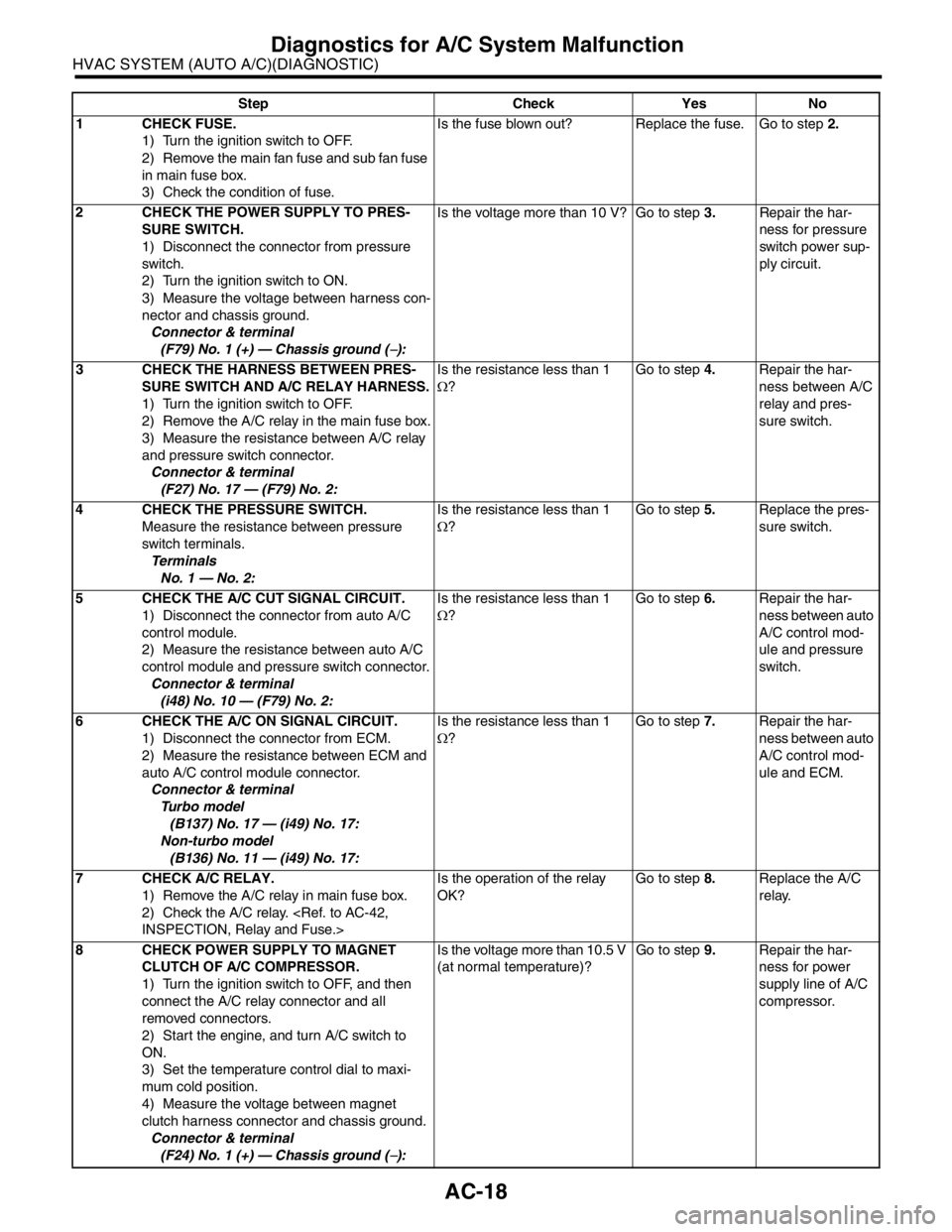
1 CHECK FUSE.
1) Turn the ignition switch to OFF.
2) Remove the main fan fuse and sub fan fuse
in main fuse box.
3) Check the condition of fuse.Is the fuse blown out? Replace the fuse. Go to step 2.
2 CHECK THE POWER SUPPLY TO PRES-
SURE SWITCH.
1) Disconnect the connector from pressure
switch.
2) Turn the ignition switch to ON.
3) Measure the voltage between harness con-
nector and chassis ground.
Connector & terminal
(F79) No. 1 (+) — Chassis ground (
−):Is the voltage more than 10 V? Go to step 3.Repair the har-
ness for pressure
switch power sup-
ply circuit.
3 CHECK THE HARNESS BETWEEN PRES-
SURE SWITCH AND A/C RELAY HARNESS.
1) Turn the ignition switch to OFF.
2) Remove the A/C relay in the main fuse box.
3) Measure the resistance between A/C relay
and pressure switch connector.
Connector & terminal
(F27) No. 17 — (F79) No. 2:Is the resistance less than 1
Ω?Go to step 4.Repair the har-
ness between A/C
relay and pres-
sure switch.
4 CHECK THE PRESSURE SWITCH.
Measure the resistance between pressure
switch terminals.
Te r m i n a l s
No. 1 — No. 2:Is the resistance less than 1
Ω?Go to step 5.Replace the pres-
sure switch.
5 CHECK THE A/C CUT SIGNAL CIRCUIT.
1) Disconnect the connector from auto A/C
control module.
2) Measure the resistance between auto A/C
control module and pressure switch connector.
Connector & terminal
(i48) No. 10 — (F79) No. 2:Is the resistance less than 1
Ω?Go to step 6.Repair the har-
ness between auto
A/C control mod-
ule and pressure
switch.
6 CHECK THE A/C ON SIGNAL CIRCUIT.
1) Disconnect the connector from ECM.
2) Measure the resistance between ECM and
auto A/C control module connector.
Connector & terminal
Turbo model
(B137) No. 17 — (i49) No. 17:
Non-turbo model
(B136) No. 11 — (i49) No. 17:Is the resistance less than 1
Ω?Go to step 7.Repair the har-
ness between auto
A/C control mod-
ule and ECM.
7 CHECK A/C RELAY.
1) Remove the A/C relay in main fuse box.
2) Check the A/C relay.
OK?Go to step 8.Replace the A/C
relay.
8 CHECK POWER SUPPLY TO MAGNET
CLUTCH OF A/C COMPRESSOR.
1) Turn the ignition switch to OFF, and then
connect the A/C relay connector and all
removed connectors.
2) Start the engine, and turn A/C switch to
ON.
3) Set the temperature control dial to maxi-
mum cold position.
4) Measure the voltage between magnet
clutch harness connector and chassis ground.
Connector & terminal
(F24) No. 1 (+) — Chassis ground (
−):Is the voltage more than 10.5 V
(at normal temperature)?Go to step 9.Repair the har-
ness for power
supply line of A/C
compressor.
Page 726 of 2870
PI-3
PRE-DELIVERY INSPECTION
Pre-delivery Inspection
B: PDI PROCEDURE
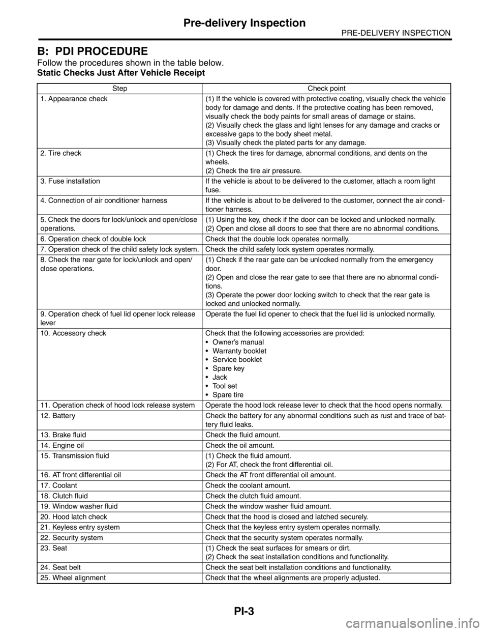
Follow the procedures shown in the table below.
Static Checks Just After Vehicle Receipt
Step Check point
1. Appearance check (1) If the vehicle is covered with protective coating, visually check the vehicle
body for damage and dents. If the protective coating has been removed,
visually check the body paints for small areas of damage or stains.
(2) Visually check the glass and light lenses for any damage and cracks or
excessive gaps to the body sheet metal.
(3) Visually check the plated parts for any damage.
2. Tire check (1) Check the tires for damage, abnormal conditions, and dents on the
wheels.
(2) Check the tire air pressure.
3. Fuse installation If the vehicle is about to be delivered to the customer, attach a room light
fuse.
4. Connection of air conditioner harness If the vehicle is about to be delivered to the customer, connect the air condi-
tioner harness.
5. Check the doors for lock/unlock and open/close
operations.(1) Using the key, check if the door can be locked and unlocked normally.
(2) Open and close all doors to see that there are no abnormal conditions.
6. Operation check of double lock Check that the double lock operates normally.
7. Operation check of the child safety lock system. Check the child safety lock system operates normally.
8. Check the rear gate for lock/unlock and open/
close operations.(1) Check if the rear gate can be unlocked normally from the emergency
door.
(2) Open and close the rear gate to see that there are no abnormal condi-
tions.
(3) Operate the power door locking switch to check that the rear gate is
locked and unlocked normally.
9. Operation check of fuel lid opener lock release
leverOperate the fuel lid opener to check that the fuel lid is unlocked normally.
10. Accessory check Check that the following accessories are provided:
Owner’s manual
Warranty booklet
Service booklet
Spare key
Jack
Tool set
Spare tire
11. Operation check of hood lock release system Operate the hood lock release lever to check that the hood opens normally.
12. Battery Check the battery for any abnormal conditions such as rust and trace of bat-
tery fluid leaks.
13. Brake fluid Check the fluid amount.
14. Engine oil Check the oil amount.
15. Transmission fluid (1) Check the fluid amount.
(2) For AT, check the front differential oil.
16. AT front differential oil Check the AT front differential oil amount.
17. Coolant Check the coolant amount.
18. Clutch fluid Check the clutch fluid amount.
19. Window washer fluid Check the window washer fluid amount.
20. Hood latch check Check that the hood is closed and latched securely.
21. Keyless entry system Check that the keyless entry system operates normally.
22. Security system Check that the security system operates normally.
23. Seat (1) Check the seat surfaces for smears or dirt.
(2) Check the seat installation conditions and functionality.
24. Seat belt Check the seat belt installation conditions and functionality.
25. Wheel alignment Check that the wheel alignments are properly adjusted.
Page 796 of 2870
FU(H4SO)-14
FUEL INJECTION (FUEL SYSTEM)
Intake Manifold
3. Intake Manifold
A: REMOVAL
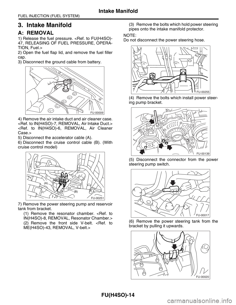
1) Release the fuel pressure.
TION, Fuel.>
2) Open the fuel flap lid, and remove the fuel filler
cap.
3) Disconnect the ground cable from battery.
4) Remove the air intake duct and air cleaner case.
5) Disconnect the accelerator cable (A).
6) Disconnect the cruise control cable (B). (With
cruise control model)
7) Remove the power steering pump and reservoir
tank from bracket.
(1) Remove the resonator chamber.
(2) Remove the front side V-belt.
pipes onto the intake manifold protector.
NOTE:
Do not disconnect the power steering hose.
(4) Remove the bolts which install power steer-
ing pump bracket.
(5) Disconnect the connector from the power
steering pump switch.
(6) Remove the power steering tank from the
bracket by pulling it upwards.
FU-00009
FU-00251
(B)
(A)
FU-00255
FU-00139
FU-00017
FU-00020
Page 799 of 2870
FU(H4SO)-17
FUEL INJECTION (FUEL SYSTEM)
Intake Manifold
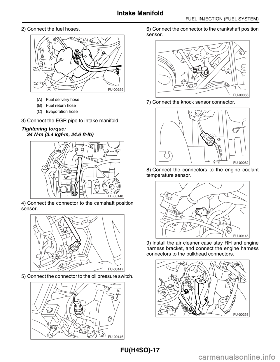
2) Connect the fuel hoses.
3) Connect the EGR pipe to intake manifold.
Tightening torque:
34 N
⋅m (3.4 kgf-m, 24.6 ft-lb)
4) Connect the connector to the camshaft position
sensor.
5) Connect the connector to the oil pressure switch.6) Connect the connector to the crankshaft position
sensor.
7) Connect the knock sensor connector.
8) Connect the connectors to the engine coolant
temperature sensor.
9) Install the air cleaner case stay RH and engine
harness bracket, and connect the engine harness
connectors to the bulkhead connectors.
(A) Fuel delivery hose
(B) Fuel return hose
(C) Evaporation hose
(B) (A)
(C)
FU-00259
FU-00148
FU-00147
FU-00146
FU-00056
FU-00062
FU-00145
FU-00258
Page 909 of 2870
ME(H4SO)-40
MECHANICAL
Engine Assembly
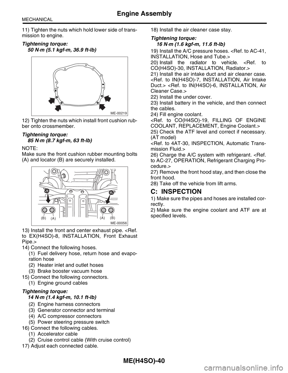
11) Tighten the nuts which hold lower side of trans-
mission to engine.
Tightening torque:
50 N
⋅m (5.1 kgf-m, 36.9 ft-lb)
12) Tighten the nuts which install front cushion rub-
ber onto crossmember.
Tightening torque:
85 N
⋅m (8.7 kgf-m, 63 ft-lb)
NOTE:
Make sure the front cushion rubber mounting bolts
(A) and locator (B) are securely installed.
13) Install the front and center exhaust pipe.
Pipe.>
14) Connect the following hoses.
(1) Fuel delivery hose, return hose and evapo-
ration hose
(2) Heater inlet and outlet hoses
(3) Brake booster vacuum hose
15) Connect the following connectors.
(1) Engine ground cables
Tightening torque:
14 N
⋅m (1.4 kgf-m, 10.1 ft-lb)
(2) Engine harness connectors
(3) Generator connector and terminal
(4) A/C compressor connectors
(5) Power steering pressure switch
16) Connect the following cables.
(1) Accelerator cable
(2) Cruise control cable (With cruise control)
17) Adjust each connected cable.18) Install the air cleaner case stay.
Tightening torque:
16 N
⋅m (1.6 kgf-m, 11.6 ft-lb)
19) Install the A/C pressure hoses.
20) Install the radiator to vehicle.
21) Install the air intake duct and air cleaner case.
22) Install the under cover.
23) Install battery in the vehicle, and then connect
the cables.
24) Fill engine coolant.
25) Check the ATF level and correct if necessary.
(AT model)
26) Charge the A/C system with refrigerant.
cedure.>
27) Remove the front hood stay, and then close the
front hood.
28) Take off the vehicle from lift arms.
C: INSPECTION
1) Make sure the pipes and hoses are installed cor-
rectly.
2) Make sure the engine coolant and ATF are at
specified levels.
ME-00219
ME-00056
(A)
(A)(B)
(B)
Page 967 of 2870
ME(H4SO)-96
MECHANICAL
Engine Noise
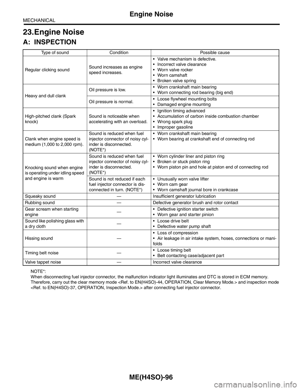
23.Engine Noise
A: INSPECTION
NOTE*:
When disconnecting fuel injector connector, the malfunction indicator light illuminates and DTC is stored in ECM memory.
Therefore, carry out the clear memory mode
Regular clicking soundSound increases as engine
speed increases. Valve mechanism is defective.
Incorrect valve clearance
Worn valve rocker
Worn camshaft
Broken valve spring
Heavy and dull clankOil pressure is low. Worn crankshaft main bearing
Worn connecting rod bearing (big end)
Oil pressure is normal. Loose flywheel mounting bolts
Damaged engine mounting
High-pitched clank (Spark
knock)Sound is noticeable when
accelerating with an overload. Ignition timing advanced
Accumulation of carbon inside combustion chamber
Wrong spark plug
Improper gasoline
Clank when engine speed is
medium (1,000 to 2,000 rpm).Sound is reduced when fuel
injector connector of noisy cyl-
inder is disconnected.
(NOTE*) Worn crankshaft main bearing
Worn bearing at crankshaft end of connecting rod
Knocking sound when engine
is operating under idling speed
and engine is warmSound is reduced when fuel
injector connector of noisy cyl-
inder is disconnected.
(NOTE*) Worn cylinder liner and piston ring
Broken or stuck piston ring
Worn piston pin and hole at piston end of connecting rod
Sound is not reduced if each
fuel injector connector is dis-
connected in turn. (NOTE*) Unusually worn valve lifter
Worn cam gear
Worn camshaft journal bore in crankcase
Squeaky sound — Insufficient generator lubrication
Rubbing sound — Defective generator brush and rotor contact
Gear scream when starting
engine— Defective ignition starter switch
Worn gear and starter pinion
Sound like polishing glass with
a dry cloth— Loose drive belt
Defective water pump shaft
Hissing sound — Loss of compression
Air leakage in air intake system, hoses, connections or mani-
folds
Timing belt noise — Loose timing belt
Belt contacting case/adjacent part
Valve tappet noise — Incorrect valve clearance
Page 1037 of 2870
LU(H4SO)-9
LUBRICATION
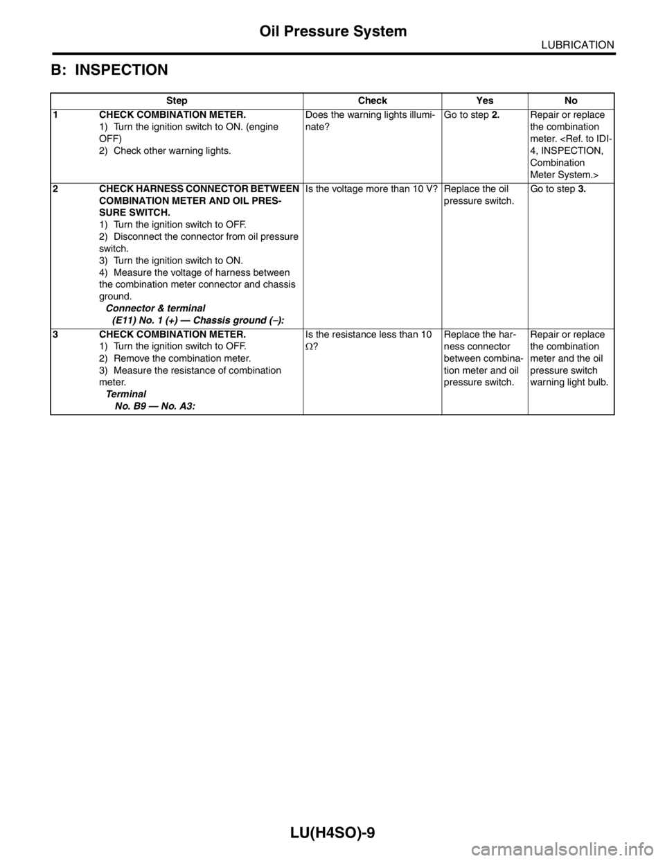
Oil Pressure System
B: INSPECTION
Step Check Yes No
1 CHECK COMBINATION METER.
1) Turn the ignition switch to ON. (engine
OFF)
2) Check other warning lights.Does the warning lights illumi-
nate?Go to step 2.Repair or replace
the combination
meter.
Combination
Meter System.>
2 CHECK HARNESS CONNECTOR BETWEEN
COMBINATION METER AND OIL PRES-
SURE SWITCH.
1) Turn the ignition switch to OFF.
2) Disconnect the connector from oil pressure
switch.
3) Turn the ignition switch to ON.
4) Measure the voltage of harness between
the combination meter connector and chassis
ground.
Connector & terminal
(E11) No. 1 (+) — Chassis ground (
−):Is the voltage more than 10 V? Replace the oil
pressure switch.Go to step 3.
3 CHECK COMBINATION METER.
1) Turn the ignition switch to OFF.
2) Remove the combination meter.
3) Measure the resistance of combination
meter.
Te r m i n a l
No. B9 — No. A3:Is the resistance less than 10
Ω?Replace the har-
ness connector
between combina-
tion meter and oil
pressure switch.Repair or replace
the combination
meter and the oil
pressure switch
warning light bulb.
Page 1052 of 2870
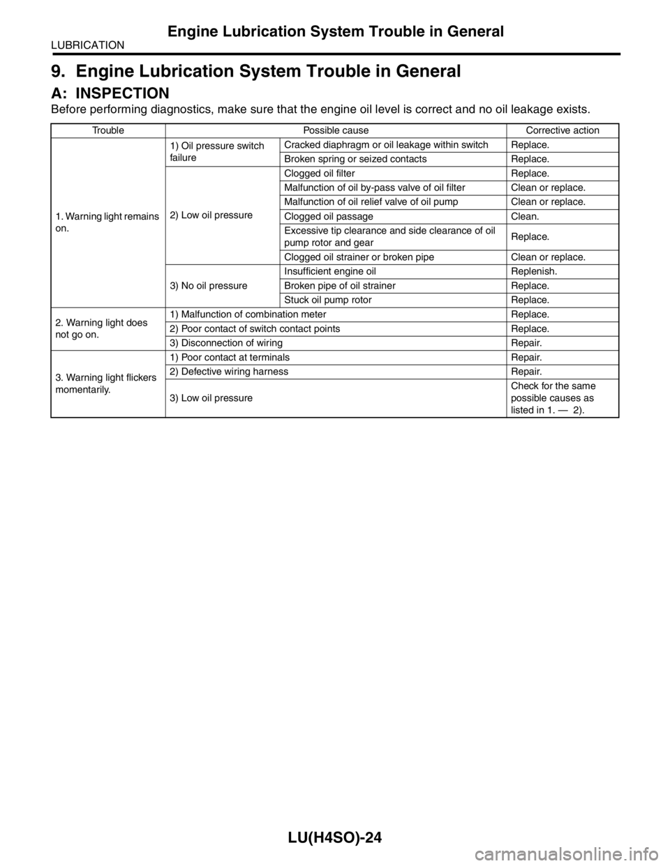
LU(H4SO)-24
LUBRICATION
Engine Lubrication System Trouble in General
9. Engine Lubrication System Trouble in General
A: INSPECTION
Before performing diagnostics, make sure that the engine oil level is correct and no oil leakage exists.
Trouble Possible cause Corrective action
1. Warning light remains
on.1) Oil pressure switch
failureCracked diaphragm or oil leakage within switch Replace.
Broken spring or seized contacts Replace.
2) Low oil pressureClogged oil filter Replace.
Malfunction of oil by-pass valve of oil filter Clean or replace.
Malfunction of oil relief valve of oil pump Clean or replace.
Clogged oil passage Clean.
Excessive tip clearance and side clearance of oil
pump rotor and gearReplace.
Clogged oil strainer or broken pipe Clean or replace.
3) No oil pressureInsufficient engine oil Replenish.
Broken pipe of oil strainer Replace.
Stuck oil pump rotor Replace.
2. Warning light does
not go on.1) Malfunction of combination meter Replace.
2) Poor contact of switch contact points Replace.
3) Disconnection of wiring Repair.
3. Warning light flickers
momentarily.1) Poor contact at terminals Repair.
2) Defective wiring harness Repair.
3) Low oil pressureCheck for the same
possible causes as
listed in 1. — 2).