air pressure switch SUBARU FORESTER 2004 Service Service Manual
[x] Cancel search | Manufacturer: SUBARU, Model Year: 2004, Model line: FORESTER, Model: SUBARU FORESTER 2004Pages: 2870, PDF Size: 38.67 MB
Page 1667 of 2870

EN(H4DOTC)-37
ENGINE (DIAGNOSTIC)
Subaru Select Monitor
7. LED OPERATION MODE FOR ENGINE
1) On the «Main Menu» display screen, select the {Each System Check} and press the [YES] key.
2) On the «System Selection Menu» display screen, select the {Engine} and press the [YES] key.
3) Press the [YES] key after the information of engine type was displayed.
4) On the «Engine Diagnosis» screen, select the {Current Data Display/Save}, and then press the [YES] key.
5) On the «Data Display» screen, select the {Data & LED Display} and press the [YES] key.
6) Using the scroll key, move the display screen up or down until the desired data is shown.
A list of the support data is shown in the following table.
NOTE:
For detailed operation procedure, refer to the “SUBARU SELECT MONITOR OPERATION MANUAL”.
Description Display Message LED “ON” requirements
Ignition switch signal Ignition Switch ON or OFF When ignition switch is ON.
Test mode connector signal Test Mode Signal ON or OFF When test mode connector is connected.
Neutral position switch signal Neutral Position Switch ON or OFF When neutral position signal is entered.
Air conditioning switch signal A/C Switch ON or OFF When air conditioning switch is ON.
Air conditioning relay signal A/C Compressor Signal ON or OFF When air conditioning relay is in function.
Radiator main fan relay signal Radiator Fan Relay #1 ON or OFF When radiator main fan relay is in function.
Knocking signal Knocking Signal ON or OFF When knocking signal is input.
Radiator sub fan relay signal Radiator Fan Relay #2 ON or OFF When radiator sub fan relay is in function.
Engine torque control permission
signalTorque Control Permission ON or OFFWhen engine torque control permission sig-
nal is entered.
Rear oxygen sensor rich signalRear O
2 Rich Signal
ON or OFFWhen rear oxygen sensor mixture ratio is
rich.
Starter switch signal Starter Switch ON or OFF When starter switch signal is entered.
Idle switch signal Idle Switch ON or OFF When idle switch signal is entered.
Crankshaft position sensor signal Crankshaft Position Signal ON or OFFWhen crankshaft position sensor signal is
input.
Camshaft position sensor signal Camshaft Position Signal ON or OFFWhen camshaft position sensor signal is
entered.
Power steering switch signal P/S Switch ON or OFF When power steering switch is entered.
Rear defogger switch signal Rear Defogger Switch ON or OFF When rear defogger switch is ON.
Blower fan switch signal Blower Fan Switch ON or OFF When blower fan switch is ON.
Light switch signal Light Switch ON or OFF When small light switch is ON.
Wiper switch signal Wiper Switch ON or OFF When wiper switch is ON.
A/C middle pressure switch signal A/C Mid Pressure Switch ON or OFF When A/C switch is ON.
AT retard angle demand signal Retard Signal from AT ON or OFF When AT retard angle demand signal exists.
AT fuel cut demand signal Fuel Cut Signal from AT ON or OFF When AT fuel cut demand signal exists.
AT/MT identification signal AT Vehicle ID Signal ON or OFF For AT model
Tumble generated valve actuator
signalTGV Output ON or OFF When TGV actuator signal is output.
Tumble generated valve drive sig-
nalTGV DriveOPEN or
CLOSEWhen TGV moves and valve opens.
Page 1668 of 2870

EN(H4DOTC)-38
ENGINE (DIAGNOSTIC)
Subaru Select Monitor
8. READ CURRENT DATA FOR AT
1) On the «Main Menu» display screen, select the {Each System Check} and press the [YES] key.
2) On the «System Selection Menu» display screen, select the {Transmission} and press the [YES] key.
3) Press the [YES] key after displayed the information of transmission type.
4) On the «Transmission Diagnosis» screen, select the {Current Data Display/Save}, and then press the
[YES] key.
5) On the «Data Display Menu» screen, select the {Data Display} and press the [YES] key.
6) Using the scroll key, move the display screen up or down until the desired data is shown.
A list of the support data is shown in the following table.
NOTE:
For detailed operation procedure, refer to the “SUBARU SELECT MONITOR OPERATION MANUAL”.
Description Display Unit of measure
Battery voltage Battery Voltage V
Rear vehicle speed sensor signal Rear Wheel Speed km/h or MPH
Front vehicle speed sensor signal Front Wheel Speed km/h or MPH
Engine speed signal Engine Speed rpm
ATF temperature signal ATF Temp.°C or °F
Mass air flow sensor signal Air Flow Sensor Voltage V
Throttle position signal Throttle Sensor Voltage V
Gear Position Gear position —
Line pressure control duty ratio Line Pressure Duty Ratio %
Lock up clutch control duty ratio Lock Up Duty Ratio %
Transfer clutch control duty ratio Transfer Duty Ratio %
Throttle position sensor power supply Throttle Sensor Power V
Turbine revolution signal Turbine Revolution Speed rpm
2-4 Brake timing pressure control duty ratio Brake Clutch Duty Ratio %
Stop light switch signal Stop Light Switch ON or OFF
Anti lock brake system signal ABS Signal ON or OFF
Cruise control system signal Cruise Control Signal ON or OFF
Neutral/Parking range signal N/P Range Signal ON or OFF
Reverse range signal R Range Signal ON or OFF
Drive range signal D Range Signal ON or OFF
3rd range signal 3rd Range Signal ON or OFF
2nd range signal 2nd Range Signal ON or OFF
1st range signal 1st Range Signal ON or OFF
Shift control solenoid A Shift Solenoid #1 ON or OFF
Shift control solenoid B Shift Solenoid #2 ON or OFF
Torque control output signal #1 Torque Control Signal #1 ON or OFF
Torque control output signal #2 Torque Control Signal #2 ON or OFF
Torque control cut signal Torque Control Cut Sig. ON or OFF
2-4 brake timing control solenoid valve 2-4 Brake Timing Sol. ON or OFF
Low clutch timing control solenoid valve Low Clutch Timing Sol. ON or OFF
Automatic transmission diagnosis indicator lamp Diagnosis Lamp ON or OFF
Page 1670 of 2870
EN(H4DOTC)-40
ENGINE (DIAGNOSTIC)
Inspection Mode
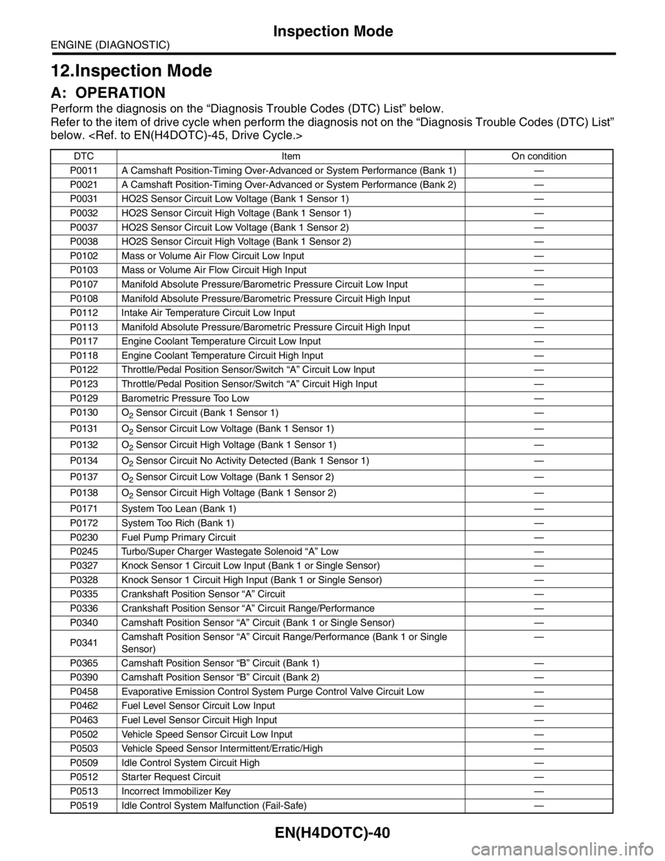
12.Inspection Mode
A: OPERATION
Perform the diagnosis on the “Diagnosis Trouble Codes (DTC) List” below.
Refer to the item of drive cycle when perform the diagnosis not on the “Diagnosis Trouble Codes (DTC) List”
below.
DTC Item On condition
P0011 A Camshaft Position-Timing Over-Advanced or System Performance (Bank 1) —
P0021 A Camshaft Position-Timing Over-Advanced or System Performance (Bank 2) —
P0031 HO2S Sensor Circuit Low Voltage (Bank 1 Sensor 1) —
P0032 HO2S Sensor Circuit High Voltage (Bank 1 Sensor 1) —
P0037 HO2S Sensor Circuit Low Voltage (Bank 1 Sensor 2) —
P0038 HO2S Sensor Circuit High Voltage (Bank 1 Sensor 2) —
P0102 Mass or Volume Air Flow Circuit Low Input —
P0103 Mass or Volume Air Flow Circuit High Input —
P0107 Manifold Absolute Pressure/Barometric Pressure Circuit Low Input —
P0108 Manifold Absolute Pressure/Barometric Pressure Circuit High Input —
P0112 Intake Air Temperature Circuit Low Input —
P0113 Manifold Absolute Pressure/Barometric Pressure Circuit High Input —
P0117 Engine Coolant Temperature Circuit Low Input —
P0118 Engine Coolant Temperature Circuit High Input —
P0122 Throttle/Pedal Position Sensor/Switch “A” Circuit Low Input —
P0123 Throttle/Pedal Position Sensor/Switch “A” Circuit High Input —
P0129 Barometric Pressure Too Low —
P0130 O
2 Sensor Circuit (Bank 1 Sensor 1) —
P0131 O
2 Sensor Circuit Low Voltage (Bank 1 Sensor 1) —
P0132 O
2 Sensor Circuit High Voltage (Bank 1 Sensor 1) —
P0134 O
2 Sensor Circuit No Activity Detected (Bank 1 Sensor 1) —
P0137 O
2 Sensor Circuit Low Voltage (Bank 1 Sensor 2) —
P0138 O
2 Sensor Circuit High Voltage (Bank 1 Sensor 2) —
P0171 System Too Lean (Bank 1) —
P0172 System Too Rich (Bank 1) —
P0230 Fuel Pump Primary Circuit —
P0245 Turbo/Super Charger Wastegate Solenoid “A” Low —
P0327 Knock Sensor 1 Circuit Low Input (Bank 1 or Single Sensor) —
P0328 Knock Sensor 1 Circuit High Input (Bank 1 or Single Sensor) —
P0335 Crankshaft Position Sensor “A” Circuit —
P0336 Crankshaft Position Sensor “A” Circuit Range/Performance —
P0340 Camshaft Position Sensor “A” Circuit (Bank 1 or Single Sensor) —
P0341Camshaft Position Sensor “A” Circuit Range/Performance (Bank 1 or Single
Sensor)—
P0365 Camshaft Position Sensor “B” Circuit (Bank 1) —
P0390 Camshaft Position Sensor “B” Circuit (Bank 2) —
P0458 Evaporative Emission Control System Purge Control Valve Circuit Low —
P0462 Fuel Level Sensor Circuit Low Input —
P0463 Fuel Level Sensor Circuit High Input —
P0502 Vehicle Speed Sensor Circuit Low Input —
P0503 Vehicle Speed Sensor Intermittent/Erratic/High —
P0509 Idle Control System Circuit High —
P0512 Starter Request Circuit—
P0513 Incorrect Immobilizer Key —
P0519 Idle Control System Malfunction (Fail-Safe) —
Page 1676 of 2870
EN(H4DOTC)-46
ENGINE (DIAGNOSTIC)
Drive Cycle
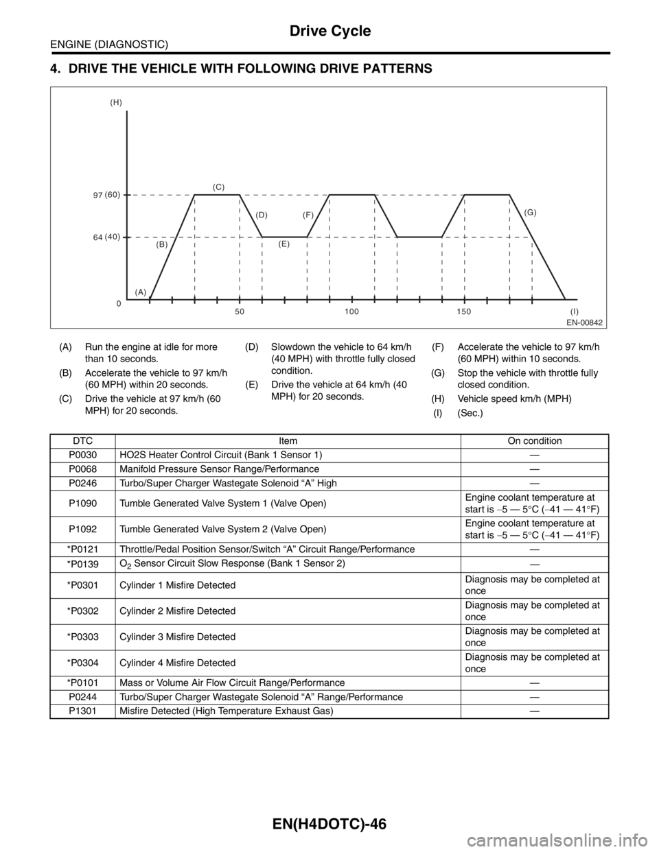
4. DRIVE THE VEHICLE WITH FOLLOWING DRIVE PATTERNS
(A) Run the engine at idle for more
than 10 seconds.(D) Slowdown the vehicle to 64 km/h
(40 MPH) with throttle fully closed
condition.(F) Accelerate the vehicle to 97 km/h
(60 MPH) within 10 seconds.
(B) Accelerate the vehicle to 97 km/h
(60 MPH) within 20 seconds.(G) Stop the vehicle with throttle fully
closed condition. (E) Drive the vehicle at 64 km/h (40
MPH) for 20 seconds.
(C) Drive the vehicle at 97 km/h (60
MPH) for 20 seconds.(H) Vehicle speed km/h (MPH)
(I) (Sec.)
DTC Item On condition
P0030 HO2S Heater Control Circuit (Bank 1 Sensor 1) —
P0068 Manifold Pressure Sensor Range/Performance —
P0246 Turbo/Super Charger Wastegate Solenoid “A” High —
P1090 Tumble Generated Valve System 1 (Valve Open)Engine coolant temperature at
start is −5 — 5°C (−41 — 41°F)
P1092 Tumble Generated Valve System 2 (Valve Open)Engine coolant temperature at
start is −5 — 5°C (−41 — 41°F)
*P0121 Throttle/Pedal Position Sensor/Switch “A” Circuit Range/Performance —
*P0139O
2 Sensor Circuit Slow Response (Bank 1 Sensor 2)
—
*P0301 Cylinder 1 Misfire DetectedDiagnosis may be completed at
once
*P0302 Cylinder 2 Misfire DetectedDiagnosis may be completed at
once
*P0303 Cylinder 3 Misfire DetectedDiagnosis may be completed at
once
*P0304 Cylinder 4 Misfire DetectedDiagnosis may be completed at
once
*P0101 Mass or Volume Air Flow Circuit Range/Performance —
P0244 Turbo/Super Charger Wastegate Solenoid “A” Range/Performance —
P1301 Misfire Detected (High Temperature Exhaust Gas) —
EN-00842
(C) (H)
(I) (60)
97
64(40)
(B)
(A)(F) (D)
(E)
150 100 50 0(G)
Page 1679 of 2870

EN(H4DOTC)-49
ENGINE (DIAGNOSTIC)
Compulsory Valve Operation Check Mode
13) Pressing the [NO] key completes the compul-
sory operation check mode.The display will then re-
turn to the «Actuator ON/OFF Operation» screen.
A list of the support data is shown in the following
table.
NOTE:
The following parts will be displayed but not func-
tional.
For detailed operation procedure, refer to the
“SUBARU SELECT MONITOR OPERATION MAN-
UAL”.
Description Display
Compulsory fuel pump relay operation
checkFuel Pump
Compulsory radiator fan relay operation
checkRadiator Fan
Relay
Compulsory air conditioning relay oper-
ation checkA/C Compressor
Relay
Compulsory purge control solenoid
valve operation checkCPC Solenoid
Compulsory wastegate control sole-
noid valve operation checkWastegate con-
trol solenoid
Display
EGR Solenoid
ASV Solenoid
PCV Solenoid
Vent Control Solenoid
FICD Solenoid
Pressure Switching Solenoid1
Pressure Switching Solenoid2
EXH. Bypass Control Permit Flag
AAI Solenoid
Atmospheric pressure switching solenoid
Page 1697 of 2870
EN(H4DOTC)-67
ENGINE (DIAGNOSTIC)
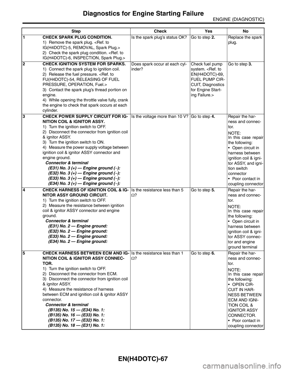
Diagnostics for Engine Starting Failure
Step Check Yes No
1 CHECK SPARK PLUG CONDITION.
1) Remove the spark plug.
2) Check the spark plug condition.
plug.
2 CHECK IGNITION SYSTEM FOR SPARKS.
1) Connect the spark plug to ignition coil.
2) Release the fuel pressure.
PRESSURE, OPERATION, Fuel.>
3) Contact the spark plug’s thread portion on
engine.
4) While opening the throttle valve fully, crank
the engine to check that spark occurs at each
cylinder.Does spark occur at each cyl-
inder?Check fuel pump
system.
FUEL PUMP CIR-
CUIT, Diagnostics
for Engine Start-
ing Failure.>Go to step 3.
3 CHECK POWER SUPPLY CIRCUIT FOR IG-
NITION COIL & IGNITOR ASSY.
1) Turn the ignition switch to OFF.
2) Disconnect the connector from ignition coil
& ignitor ASSY.
3) Turn the ignition switch to ON.
4) Measure the power supply voltage between
ignition coil & ignitor ASSY connector and
engine ground.
Connector & terminal
(E31) No. 3 (+) — Engine ground (
−):
(E32) No. 3 (+) — Engine ground (
−):
(E33) No. 3 (+) — Engine ground (
−):
(E34) No. 3 (+) — Engine ground (
−):Is the voltage more than 10 V? Go to step 4.Repair the har-
ness and connec-
tor.
N
OTE:
In this case repair
the following:
Open circuit in
harness between
ignition coil & igni-
tor ASSY, and igni-
tion switch
connector
Poor contact in
coupling connector
4 CHECK HARNESS OF IGNITION COIL & IG-
NITOR ASSY GROUND CIRCUIT.
1) Turn the ignition switch to OFF.
2) Measure the resistance between ignition
coil & ignitor ASSY connector and engine
ground.
Connector & terminal
(E31) No. 2 — Engine ground:
(E32) No. 2 — Engine ground:
(E33) No. 2 — Engine ground:
(E34) No. 2 — Engine ground:Is the resistance less than 5
Ω?Go to step 5.Repair the har-
ness and connec-
tor.
NOTE:
In this case repair
the following:
Open circuit in
harness between
ignition coil & igni-
tor ASSY connec-
tor and engine
ground terminal
5 CHECK HARNESS BETWEEN ECM AND IG-
NITION COIL & IGNITOR ASSY CONNEC-
TOR.
1) Turn the ignition switch to OFF.
2) Disconnect the connector from ECM.
3) Disconnect the connector from ignition coil
& ignitor ASSY.
4) Measure the resistance of harness
between ECM and ignition coil & ignitor ASSY
connector.
Connector & terminal
(B135) No. 15 — (E34) No. 1:
(B135) No. 16 — (E33) No. 1:
(B135) No. 17 — (E32) No. 1:
(B135) No. 18 — (E31) No. 1:Is the resistance less than 1
Ω?Go to step 6.Repair the har-
ness and connec-
tor.
N
OTE:
In this case repair
the following:
OPEN CIR-
CUIT IN HAR-
NESS BETWEEN
ECM AND IGNI-
TION COIL &
IGNITOR ASSY
CONNECTOR.
Poor contact in
coupling connector
Page 1703 of 2870

EN(H4DOTC)-73
ENGINE (DIAGNOSTIC)
Diagnostics for Engine Starting Failure
Step Check Yes No
1 CHECK OPERATION OF EACH FUEL INJEC-
TOR.
While cranking the engine, check that each
fuel injector emits operating sound.Use a
sound scope or attach a screwdriver to the
injector for this check.Does the fuel pump produce
operating sound?Check the fuel
pressure.
INSPECTION,
Fuel Pressure.>Go to step 2.
2 CHECK POWER SUPPLY TO EACH FUEL
INJECTOR.
1) Turn the ignition switch to OFF.
2) Disconnect the connector from fuel injector.
3) Turn the ignition switch to ON.
4) Measure the power supply voltage between
fuel injector terminal and engine ground.
Connector & terminal
#1 (E5) No. 2 (+) — Engine ground (
−):
#2 (E16) No. 2 (+) — Engine ground (
−):
#3 (E6) No. 2 (+) — Engine ground (
−):
#4 (E17) No. 2 (+) — Engine ground (
−):Is the voltage more than 10 V? Go to step 3.Repair the har-
ness and connec-
tor.
N
OTE:
In this case repair
the following:
Open circuit in
harness between
main relay and fuel
injector connector
Poor contact in
main relay connec-
tor
Poor contact in
coupling connector
Poor contact in
fuel injector con-
nector
3 CHECK HARNESS BETWEEN ECM AND
FUEL INJECTOR CONNECTOR.
1) Disconnect the connector from ECM.
2) Measure the resistance of harness
between ECM and fuel injector connector.
Connector & terminal
(B136) No. 6 — (E5) No. 1:
(B136) No. 5 — (E16) No. 1:
(B136) No. 4 — (E6) No. 1:
(B136) No. 3 — (E6) No. 1:Is the resistance less than 1
Ω?Go to step 4.Repair the har-
ness and connec-
tor.
NOTE:
In this case repair
the following:
Open circuit in
harness between
ECM and fuel
injector connector
Poor contact in
coupling connector
4 CHECK HARNESS BETWEEN ECM AND
FUEL INJECTOR CONNECTOR.
Measure the resistance of harness between
ECM and fuel injector connector.
Connector & terminal
(B136) No. 6 — Chassis ground:
(B136) No. 5 — Chassis ground:
(B136) No. 4 — Chassis ground:
(B136) No. 3 — Chassis ground:Is the resistance less than 1
Ω?Repair ground
short circuit in har-
ness between
ECM and fuel
injector connector.Go to step 5.
5 CHECK EACH FUEL INJECTOR.
1) Turn the ignition switch to OFF.
2) Measure the resistance between each fuel
injector terminals.
Te r m i n a l s
No. 1 — No. 2:Is the resistance 5 — 20 Ω? Go to step 6.Replace the faulty
fuel injector.
6 CHECK POOR CONTACT.
Check poor contact in ECM connector.Is there poor contact in ECM
connector?Repair the poor
contact in ECM
connector.Inspection using
“General Diagnos-
tic Table”
295, INSPEC-
TION, General
Diagnostic Table.>
Page 1708 of 2870

EN(H4DOTC)-78
ENGINE (DIAGNOSTIC)
List of Diagnostic Trouble Code (DTC)
P1089 Tumble Generated Valve Position
Sensor 1 Circuit High
tic Trouble Code (DTC).>
P1090 Tumble Generated Valve System 1
(Valve Open)
Code (DTC).>
P1091 Tumble Generated Valve System 1
(Valve Close)
Code (DTC).>
P1092 Tumble Generated Valve System 2
(Valve Open)
Code (DTC).>
P1093 Tumble Generated Valve System 2
(Valve Close)
Code (DTC).>
P1094 Tumble Generated Valve Signal 1
Circuit Malfunction (Open)
Diagnostic Trouble Code (DTC).>
P1095 Tumble Generated Valve Signal 1
Circuit Malfunction (Short)
Diagnostic Trouble Code (DTC).>
P1096 Tumble Generated Valve Signal 2
Circuit Malfunction (Open)
Diagnostic Trouble Code (DTC).>
P1097 Tumble Generated Valve Signal 2
Circuit Malfunction (Short)
Diagnostic Trouble Code (DTC).>
P1110 Atmospheric Pressure Sensor Cir-
cuit Malfunction (Low Input)
Diagnostic Trouble Code (DTC).>
P1111 Atmospheric Pressure Sensor Cir-
cuit Malfunction (High Input)
Diagnostic Trouble Code (DTC).>
P1152 O
2 Sensor Circuit Range/Perfor-
mance (Low) (Bank 1 Sensor 1)
Diagnostic Trouble Code (DTC).>
P1153 O
2 Sensor Circuit Range/Perfor-
mance (High) (Bank 1 Sensor 1)
Diagnostic Trouble Code (DTC).>
P1301 Misfire Detected (High Tempera-
ture Exhaust Gas)
Code (DTC).>
P1312 Exhaust Gas Temperature Sensor
Malfunction
ble Code (DTC).>
P1518 Starter Switch Circuit Low Input
P1544 Exhaust Gas Temperature Too
High
P1560 Back-Up Voltage Circuit Malfunc-
tion
(DTC).>
P1570 ANTENNA
P1571 Reference Code Incompatibility
Page 1739 of 2870

EN(H4DOTC)-106
ENGINE (DIAGNOSTIC)
Diagnostic Procedure with Diagnostic Trouble Code (DTC)
Step Check Yes No
1 CHECK INPUT SIGNAL FROM ECM.
Measure the voltage between ECM connector
and chassis ground.
Connector & terminal
(B136) No. 16 (+) — Chassis ground (
−):Is the voltage more than 4.5 V? Go to step 3.Go to step 2.
2 CHECK INPUT SIGNAL FROM ECM.
Measure the voltage between ECM connector
and chassis ground.
Connector & terminal
(B136) No. 16 (+) — Chassis ground (
−):Does the voltage change by
shaking the harness and con-
nector of ECM while monitor-
ing the value with voltage
meter?Repair the poor
contact in ECM
connector.Contact the SUB-
ARU dealer.
N
OTE:
Inspection by DTM
is required, be-
cause probable
cause is deteriora-
tion of multiple
parts.
3 CHECK INPUT SIGNAL FROM ECM.
Measure the voltage between ECM and chas-
sis ground.
Connector & terminal
(B136) No. 22 (+) — Chassis ground (
−):Is the voltage less than 0.7 V? Go to step 4.Contact the SUB-
ARU dealer.
N
OTE:
Inspection by DTM
is required, be-
cause probable
cause is deteriora-
tion of multiple
parts.
4 CHECK HARNESS BETWEEN ECM AND
MANIFOLD ABSOLUTE PRESSURE SEN-
SOR CONNECTOR.
1) Turn the ignition switch to OFF.
2) Disconnect the connector from the manifold
absolute pressure sensor.
3) Turn the ignition switch to ON.
4) Measure the voltage between manifold
absolute pressure sensor connector and
engine ground.
Connector & terminal
(E21) No. 3 (+) — Engine ground (
−):Is the voltage more than 4.5 V? Go to step 5.Repair the open
circuit in harness
between ECM and
manifold absolute
pressure sensor
connector.
5 CHECK HARNESS BETWEEN ECM AND
MANIFOLD ABSOLUTE PRESSURE SEN-
SOR CONNECTOR.
1) Turn the ignition switch to OFF.
2) Disconnect the connector from ECM.
3) Measure the resistance of harness
between ECM and manifold absolute pressure
sensor connector.
Connector & terminal
(B136) No. 35 — (E21) No. 2:Is the resistance less than 1
Ω?Go to step 6.Repair the open
circuit in harness
between ECM and
manifold absolute
pressure sensor
connector.
6 CHECK HARNESS BETWEEN ECM AND
MANIFOLD ABSOLUTE PRESSURE SEN-
SOR CONNECTOR.
Measure the resistance of harness between
manifold absolute pressure sensor connector
and engine ground.
Connector & terminal
(E21) No. 1 — Engine ground:Is the resistance more than 1
MΩ?Go to step 7.Repair the ground
short circuit in har-
ness between
ECM and mani-
fold absolute pres-
sure sensor
connector.
7 CHECK POOR CONTACT.
Check poor contact in manifold absolute pres-
sure sensor connector.Is there poor contact in mani-
fold absolute pressure sensor
connector?Repair poor con-
tact in manifold
absolute pressure
sensor connector.Replace the mani-
fold absolute pres-
sure sensor.
36, Manifold Abso-
lute Pressure Sen-
sor.>
Page 1742 of 2870

EN(H4DOTC)-109
ENGINE (DIAGNOSTIC)
Diagnostic Procedure with Diagnostic Trouble Code (DTC)
Step Check Yes No
1 CHECK INPUT SIGNAL FROM ECM.
Measure the voltage between ECM connector
and chassis ground.
Connector & terminal
(B136) No. 16 (+) — Chassis ground (
−):Is the voltage more than 4.5 V? Go to step 3.Go to step 2.
2 CHECK INPUT SIGNAL FROM ECM.
Measure the voltage between ECM connector
and chassis ground.
Connector & terminal
(B136) No. 16 (+) — Chassis ground (
−):Does the voltage change by
shaking the harness and con-
nector of ECM while monitor-
ing the value with voltage
meter?Repair the poor
contact in ECM
connector.Contact the SUB-
ARU dealer.
N
OTE:
Inspection by DTM
is required, be-
cause probable
cause is deteriora-
tion of multiple
parts.
3 CHECK INPUT SIGNAL FROM ECM.
Measure the voltage between ECM connector
and chassis ground.
Connector & terminal
(B136) No. 22 (+) — Chassis ground (
−):Is the voltage more than 4.5 V? Go to step 4.Contact the SUB-
ARU dealer.
N
OTE:
Inspection by DTM
is required, be-
cause probable
cause is deteriora-
tion of multiple
parts.
4 CHECK HARNESS BETWEEN ECM AND
MANIFOLD ABSOLUTE PRESSURE SEN-
SOR CONNECTOR.
1) Turn the ignition switch to OFF.
2) Disconnect the connector from the manifold
absolute pressure sensor.
3) Turn the ignition switch to ON.
4) Measure the voltage between manifold
absolute pressure sensor connector and
engine ground.
Connector & terminal
(E21) No. 3 (+) — Engine ground (
−):Is the voltage more than 4.5 V? Go to step 5.Repair the open
circuit in harness
between ECM and
manifold absolute
pressure sensor
connector.
5 CHECK HARNESS BETWEEN ECM AND
MANIFOLD ABSOLUTE PRESSURE SEN-
SOR CONNECTOR.
1) Turn the ignition switch to OFF.
2) Disconnect the connector from ECM.
3) Measure the resistance of harness
between ECM and manifold absolute pressure
sensor connector.
Connector & terminal
(B136) No. 22 — (E21) No. 1:Is the resistance less than 1
Ω?Go to step 6.Repair the open
circuit in harness
between ECM and
manifold absolute
pressure sensor
connector.
6 CHECK HARNESS BETWEEN ECM AND
MANIFOLD ABSOLUTE PRESSURE SEN-
SOR CONNECTOR.
Measure the resistance of harness between
ECM and manifold absolute pressure sensor
connector.
Connector & terminal
(B136) No. 35 — (E21) No. 2:Is the resistance less than 1
Ω?Go to step 7.Repair the open
circuit in harness
between ECM and
manifold absolute
pressure sensor
connector.
7 CHECK POOR CONTACT.
Check poor contact in manifold absolute pres-
sure sensor connector. Is there poor contact in mani-
fold absolute pressure sensor
connector?Repair poor con-
tact in manifold
absolute pressure
sensor connector.Replace the mani-
fold absolute pres-
sure sensor.
36, Manifold Abso-
lute Pressure Sen-
sor.>