air pressure switch SUBARU FORESTER 2004 Service Owner's Guide
[x] Cancel search | Manufacturer: SUBARU, Model Year: 2004, Model line: FORESTER, Model: SUBARU FORESTER 2004Pages: 2870, PDF Size: 38.67 MB
Page 1237 of 2870
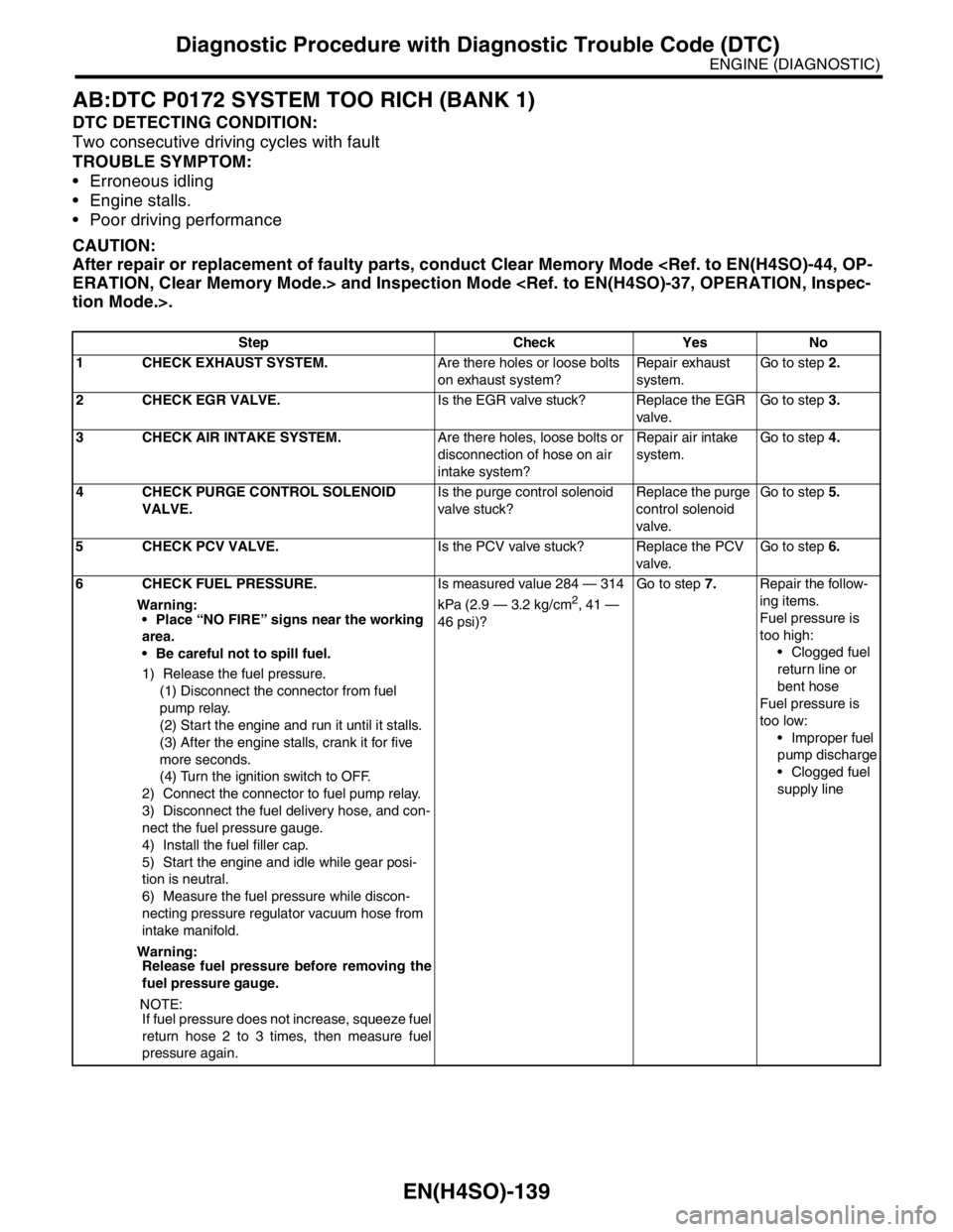
EN(H4SO)-139
ENGINE (DIAGNOSTIC)
Diagnostic Procedure with Diagnostic Trouble Code (DTC)
AB:DTC P0172 SYSTEM TOO RICH (BANK 1)
DTC DETECTING CONDITION:
Two consecutive driving cycles with fault
TROUBLE SYMPTOM:
Erroneous idling
Engine stalls.
Poor driving performance
CAUTION:
After repair or replacement of faulty parts, conduct Clear Memory Mode
Step Check Yes No
1 CHECK EXHAUST SYSTEM.Are there holes or loose bolts
on exhaust system?Repair exhaust
system.Go to step 2.
2 CHECK EGR VALVE.Is the EGR valve stuck? Replace the EGR
valve.Go to step 3.
3 CHECK AIR INTAKE SYSTEM.Are there holes, loose bolts or
disconnection of hose on air
intake system?Repair air intake
system.Go to step 4.
4 CHECK PURGE CONTROL SOLENOID
VALVE.Is the purge control solenoid
valve stuck?Replace the purge
control solenoid
valve.Go to step 5.
5 CHECK PCV VALVE.Is the PCV valve stuck? Replace the PCV
valve.Go to step 6.
6 CHECK FUEL PRESSURE.
Warning:
Place “NO FIRE” signs near the working
area.
Be careful not to spill fuel.
1) Release the fuel pressure.
(1) Disconnect the connector from fuel
pump relay.
(2) Start the engine and run it until it stalls.
(3) After the engine stalls, crank it for five
more seconds.
(4) Turn the ignition switch to OFF.
2) Connect the connector to fuel pump relay.
3) Disconnect the fuel delivery hose, and con-
nect the fuel pressure gauge.
4) Install the fuel filler cap.
5) Start the engine and idle while gear posi-
tion is neutral.
6) Measure the fuel pressure while discon-
necting pressure regulator vacuum hose from
intake manifold.
Warning:
Release fuel pressure before removing the
fuel pressure gauge.
NOTE:
If fuel pressure does not increase, squeeze fuel
return hose 2 to 3 times, then measure fuel
pressure again.Is measured value 284 — 314
kPa (2.9 — 3.2 kg/cm
2, 41 —
46 psi)?Go to step 7.Repair the follow-
ing items.
Fuel pressure is
too high:
Clogged fuel
return line or
bent hose
Fuel pressure is
too low:
Improper fuel
pump discharge
Clogged fuel
supply line
Page 1238 of 2870
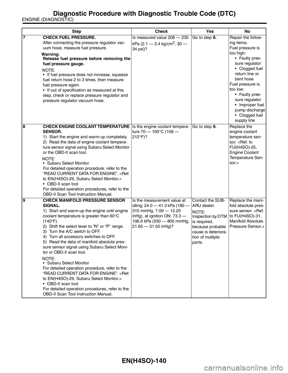
EN(H4SO)-140
ENGINE (DIAGNOSTIC)
Diagnostic Procedure with Diagnostic Trouble Code (DTC)
7 CHECK FUEL PRESSURE.
After connecting the pressure regulator vac-
uum hose, measure fuel pressure.
Warning:
Release fuel pressure before removing the
fuel pressure gauge.
N
OTE:
If fuel pressure does not increase, squeeze
fuel return hose 2 to 3 times, then measure
fuel pressure again.
If out of specification as measured at this
step, check or replace pressure regulator and
pressure regulator vacuum hose.Is measured value 206 — 235
kPa (2.1 — 2.4 kg/cm
2, 30 —
34 psi)?Go to step 8.Repair the follow-
ing items.
Fuel pressure is
too high:
Faulty pres-
sure regulator
Clogged fuel
return line or
bent hose
Fuel pressure is
too low:
Faulty pres-
sure regulator
Improper fuel
pump discharge
Clogged fuel
supply line
8 CHECK ENGINE COOLANT TEMPERATURE
SENSOR.
1) Start the engine and warm-up completely.
2) Read the data of engine coolant tempera-
ture sensor signal using Subaru Select Monitor
or the OBD-II scan tool.
NOTE:
Subaru Select Monitor
For detailed operation procedure, refer to the
“READ CURRENT DATA FOR ENGINE”.
OBD-II scan tool
For detailed operation procedures, refer to the
OBD-II Scan Tool Instruction Manual.Is the engine coolant tempera-
ture 70 — 100°C (158 —
212°F)?Go to step 9.Replace the
engine coolant
temperature sen-
sor.
Engine Coolant
Temperature Sen-
sor.>
9 CHECK MANIFOLD PRESSURE SENSOR
SIGNAL.
1) Start and warm-up the engine until engine
coolant temperature is greater than 60°C
(140°F).
2) Shift the select lever to “N” or “P” range.
3) Turn the A/C switch to OFF.
4) Turn all accessory switches to OFF.
5) Read the data of manifold absolute pres-
sure sensor signal using Subaru Select Moni-
tor or OBD-II scan tool.
NOTE:
Subaru Select Monitor
For detailed operation procedure, refer to the
“READ CURRENT DATA FOR ENGINE”.
OBD-II scan tool
For detailed operation procedures, refer to the
OBD-II Scan Tool Instruction Manual.Is the measurement value at
idling: 24.0 — 41.3 kPa (180 —
310 mmHg, 7.09 — 12.20
inHg), at ignition ON: 73.3 —
106.6 kPa (550 — 800 mmHg,
21.65 — 31.50 inHg)?Contact the SUB-
ARU dealer.
NOTE:
Inspection by DTM
is required,
because probable
cause is deteriora-
tion of multiple
parts.Replace the mani-
fold absolute pres-
sure sensor.
Manifold Absolute
Pressure Sensor.> Step Check Yes No
Page 1260 of 2870
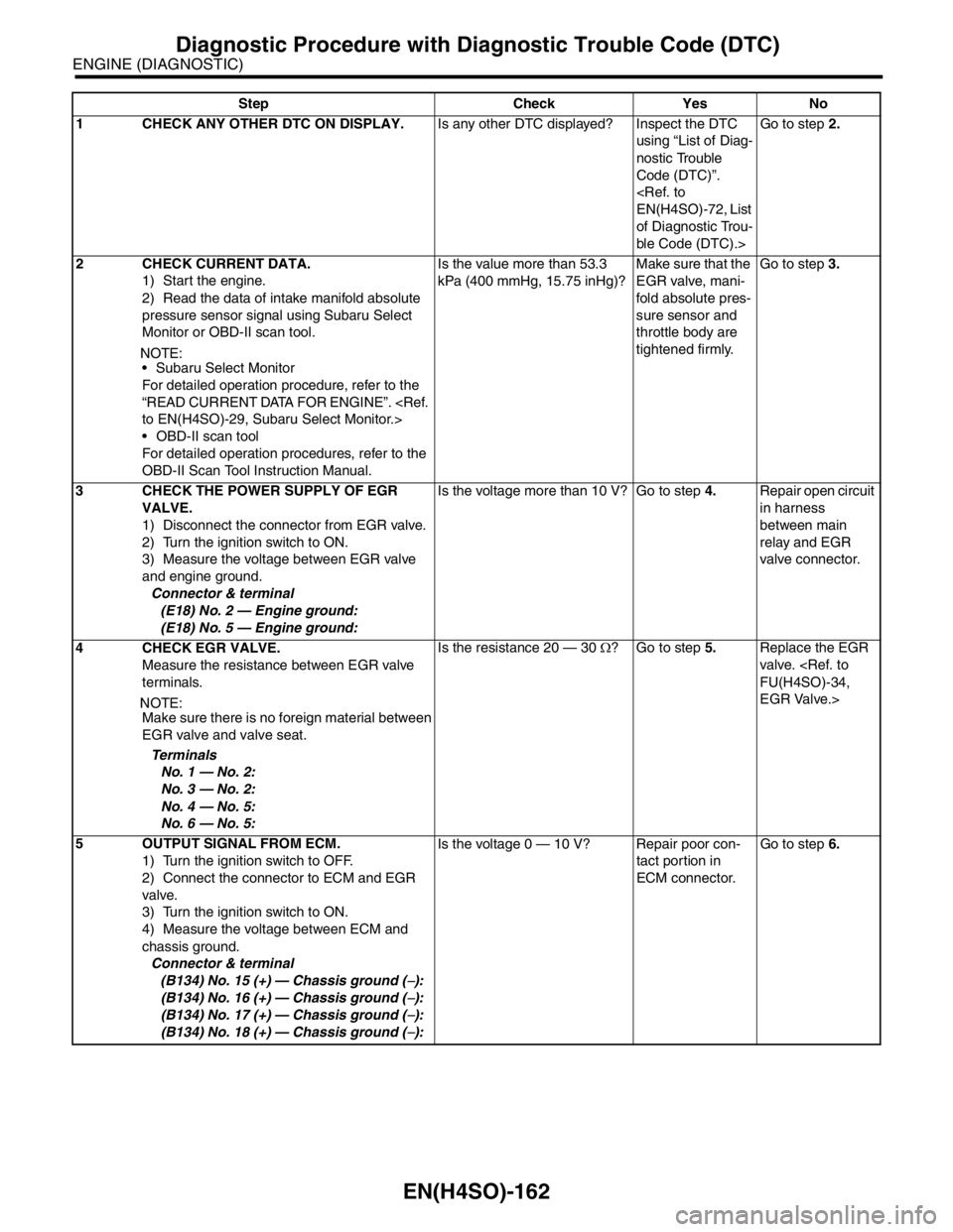
EN(H4SO)-162
ENGINE (DIAGNOSTIC)
Diagnostic Procedure with Diagnostic Trouble Code (DTC)
Step Check Yes No
1 CHECK ANY OTHER DTC ON DISPLAY.Is any other DTC displayed? Inspect the DTC
using “List of Diag-
nostic Trouble
Code (DTC)”.
of Diagnostic Trou-
ble Code (DTC).>Go to step 2.
2 CHECK CURRENT DATA.
1) Start the engine.
2) Read the data of intake manifold absolute
pressure sensor signal using Subaru Select
Monitor or OBD-II scan tool.
N
OTE:
Subaru Select Monitor
For detailed operation procedure, refer to the
“READ CURRENT DATA FOR ENGINE”.
OBD-II scan tool
For detailed operation procedures, refer to the
OBD-II Scan Tool Instruction Manual.Is the value more than 53.3
kPa (400 mmHg, 15.75 inHg)?Make sure that the
EGR valve, mani-
fold absolute pres-
sure sensor and
throttle body are
tightened firmly.Go to step 3.
3 CHECK THE POWER SUPPLY OF EGR
VALVE.
1) Disconnect the connector from EGR valve.
2) Turn the ignition switch to ON.
3) Measure the voltage between EGR valve
and engine ground.
Connector & terminal
(E18) No. 2 — Engine ground:
(E18) No. 5 — Engine ground:Is the voltage more than 10 V? Go to step 4.Repair open circuit
in harness
between main
relay and EGR
valve connector.
4 CHECK EGR VALVE.
Measure the resistance between EGR valve
terminals.
N
OTE:
Make sure there is no foreign material between
EGR valve and valve seat.
Te r m i n a l s
No. 1 — No. 2:
No. 3 — No. 2:
No. 4 — No. 5:
No. 6 — No. 5:Is the resistance 20 — 30 Ω? Go to step 5.Replace the EGR
valve.
EGR Valve.>
5 OUTPUT SIGNAL FROM ECM.
1) Turn the ignition switch to OFF.
2) Connect the connector to ECM and EGR
valve.
3) Turn the ignition switch to ON.
4) Measure the voltage between ECM and
chassis ground.
Connector & terminal
(B134) No. 15 (+) — Chassis ground (
−):
(B134) No. 16 (+) — Chassis ground (
−):
(B134) No. 17 (+) — Chassis ground (
−):
(B134) No. 18 (+) — Chassis ground (
−):Is the voltage 0 — 10 V? Repair poor con-
tact portion in
ECM connector.Go to step 6.
Page 1353 of 2870
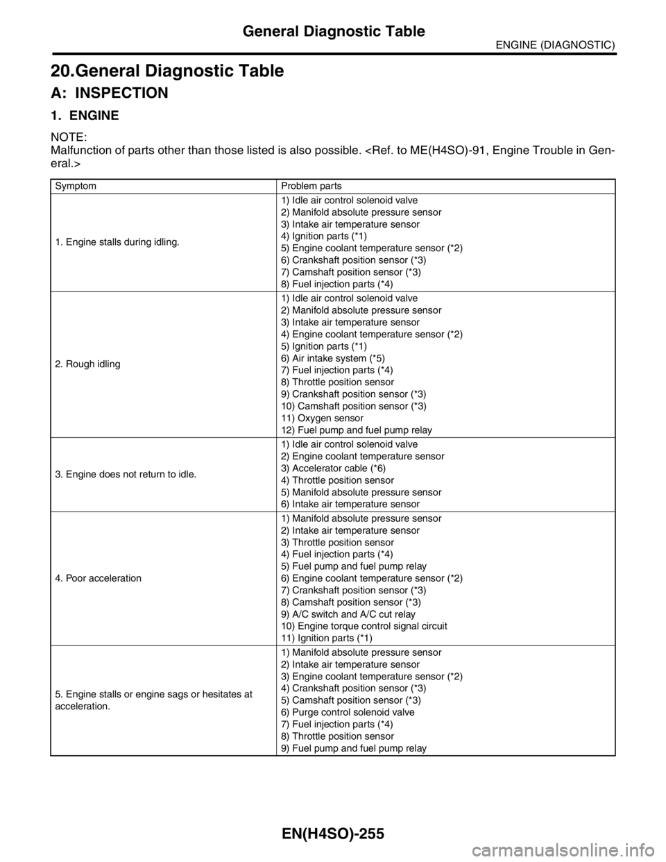
EN(H4SO)-255
ENGINE (DIAGNOSTIC)
General Diagnostic Table
20.General Diagnostic Table
A: INSPECTION
1. ENGINE
NOTE:
Malfunction of parts other than those listed is also possible.
Symptom Problem parts
1. Engine stalls during idling.1) Idle air control solenoid valve
2) Manifold absolute pressure sensor
3) Intake air temperature sensor
4) Ignition parts (*1)
5) Engine coolant temperature sensor (*2)
6) Crankshaft position sensor (*3)
7) Camshaft position sensor (*3)
8) Fuel injection parts (*4)
2. Rough idling1) Idle air control solenoid valve
2) Manifold absolute pressure sensor
3) Intake air temperature sensor
4) Engine coolant temperature sensor (*2)
5) Ignition parts (*1)
6) Air intake system (*5)
7) Fuel injection parts (*4)
8) Throttle position sensor
9) Crankshaft position sensor (*3)
10) Camshaft position sensor (*3)
11) Oxygen sensor
12) Fuel pump and fuel pump relay
3. Engine does not return to idle.1) Idle air control solenoid valve
2) Engine coolant temperature sensor
3) Accelerator cable (*6)
4) Throttle position sensor
5) Manifold absolute pressure sensor
6) Intake air temperature sensor
4. Poor acceleration1) Manifold absolute pressure sensor
2) Intake air temperature sensor
3) Throttle position sensor
4) Fuel injection parts (*4)
5) Fuel pump and fuel pump relay
6) Engine coolant temperature sensor (*2)
7) Crankshaft position sensor (*3)
8) Camshaft position sensor (*3)
9) A/C switch and A/C cut relay
10) Engine torque control signal circuit
11) Ignition parts (*1)
5. Engine stalls or engine sags or hesitates at
acceleration.1) Manifold absolute pressure sensor
2) Intake air temperature sensor
3) Engine coolant temperature sensor (*2)
4) Crankshaft position sensor (*3)
5) Camshaft position sensor (*3)
6) Purge control solenoid valve
7) Fuel injection parts (*4)
8) Throttle position sensor
9) Fuel pump and fuel pump relay
Page 1369 of 2870
FU(H4DOTC)-14
FUEL INJECTION (FUEL SYSTEM)
Intake Manifold
3. Intake Manifold
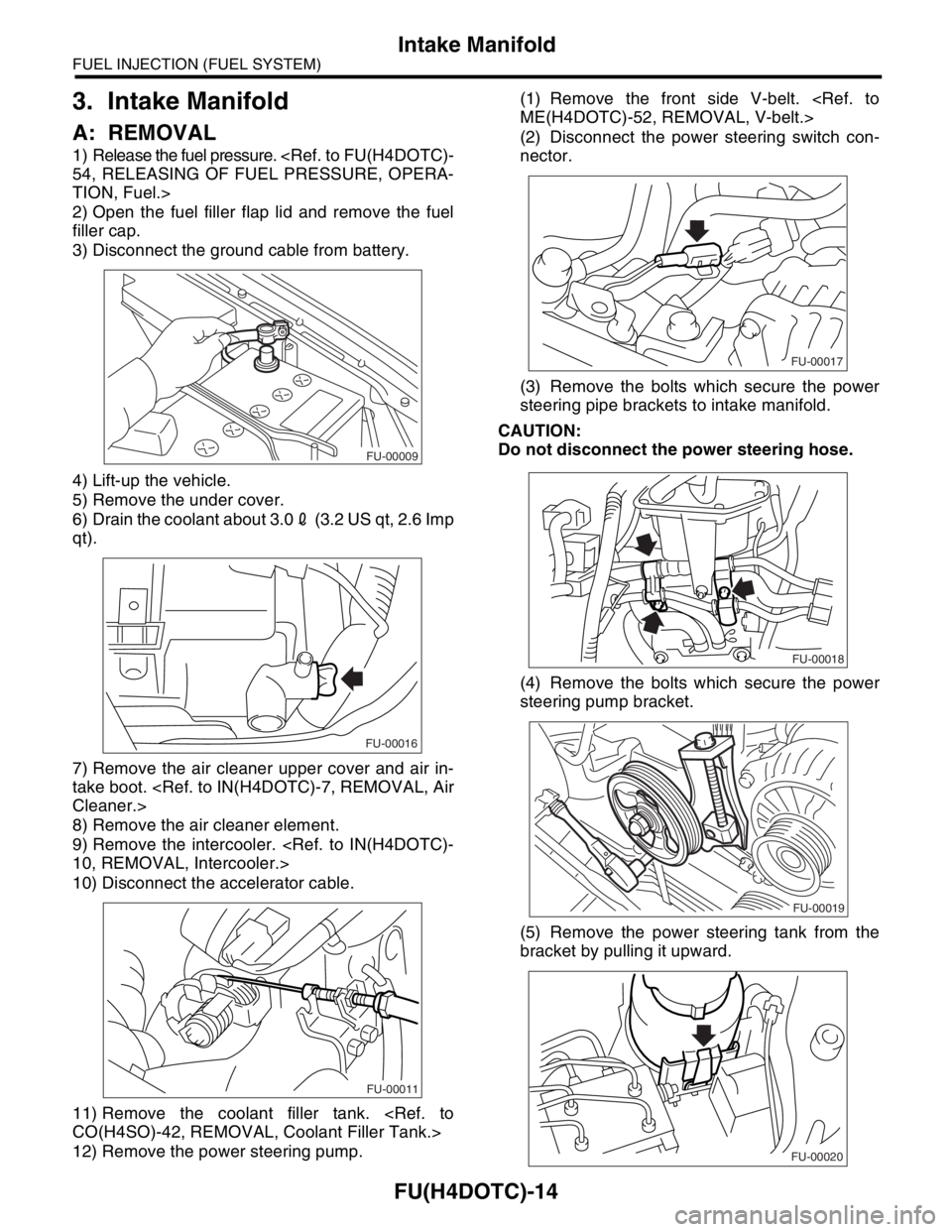
A: REMOVAL
1) Release the fuel pressure.
TION, Fuel.>
2) Open the fuel filler flap lid and remove the fuel
filler cap.
3) Disconnect the ground cable from battery.
4) Lift-up the vehicle.
5) Remove the under cover.
6) Drain the coolant about 3.02 (3.2 US qt, 2.6 Imp
qt).
7) Remove the air cleaner upper cover and air in-
take boot.
8) Remove the air cleaner element.
9) Remove the intercooler.
10) Disconnect the accelerator cable.
11) Remove the coolant filler tank.
12) Remove the power steering pump.(1) Remove the front side V-belt.
(2) Disconnect the power steering switch con-
nector.
(3) Remove the bolts which secure the power
steering pipe brackets to intake manifold.
CAUTION:
Do not disconnect the power steering hose.
(4) Remove the bolts which secure the power
steering pump bracket.
(5) Remove the power steering tank from the
bracket by pulling it upward.
FU-00009
FU-00016
FU-00011
FU-00017
FU-00018
FU-00019
FU-00020
Page 1488 of 2870
ME(H4DOTC)-32
MECHANICAL
Idle Speed
3. Idle Speed
A: INSPECTION
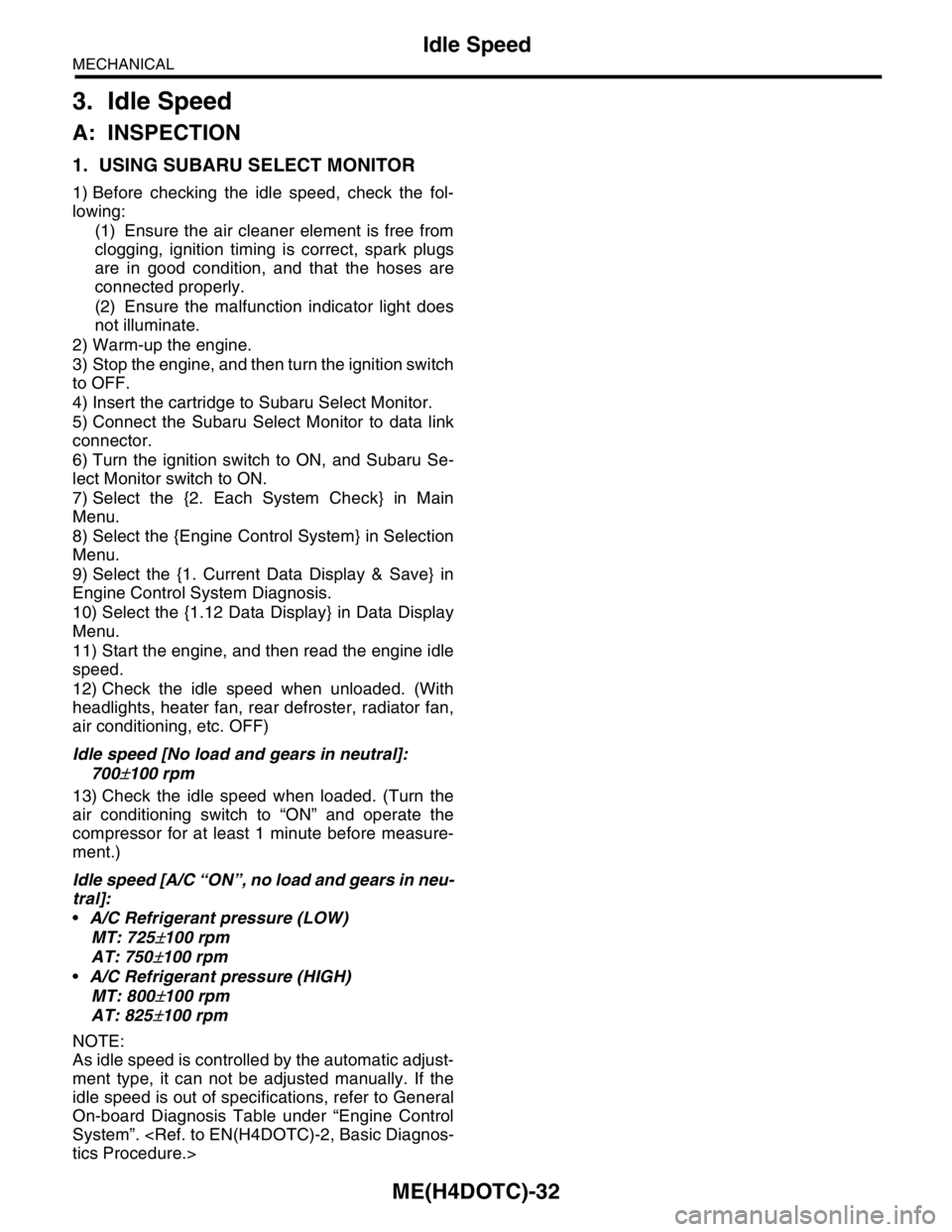
1. USING SUBARU SELECT MONITOR
1) Before checking the idle speed, check the fol-
lowing:
(1) Ensure the air cleaner element is free from
clogging, ignition timing is correct, spark plugs
are in good condition, and that the hoses are
connected properly.
(2) Ensure the malfunction indicator light does
not illuminate.
2) Warm-up the engine.
3) Stop the engine, and then turn the ignition switch
to OFF.
4) Insert the cartridge to Subaru Select Monitor.
5) Connect the Subaru Select Monitor to data link
connector.
6) Turn the ignition switch to ON, and Subaru Se-
lect Monitor switch to ON.
7) Select the {2. Each System Check} in Main
Menu.
8) Select the {Engine Control System} in Selection
Menu.
9) Select the {1. Current Data Display & Save} in
Engine Control System Diagnosis.
10) Select the {1.12 Data Display} in Data Display
Menu.
11) Start the engine, and then read the engine idle
speed.
12) Check the idle speed when unloaded. (With
headlights, heater fan, rear defroster, radiator fan,
air conditioning, etc. OFF)
Idle speed [No load and gears in neutral]:
700
±100 rpm
13) Check the idle speed when loaded. (Turn the
air conditioning switch to “ON” and operate the
compressor for at least 1 minute before measure-
ment.)
Idle speed [A/C “ON”, no load and gears in neu-
tral]:
A/C Refrigerant pressure (LOW)
MT: 725
±100 rpm
AT: 750
±100 rpm
A/C Refrigerant pressure (HIGH)
MT: 800
±100 rpm
AT: 825
±100 rpm
NOTE:
As idle speed is controlled by the automatic adjust-
ment type, it can not be adjusted manually. If the
idle speed is out of specifications, refer to General
On-board Diagnosis Table under “Engine Control
System”.
Page 1583 of 2870
ME(H4DOTC)-123
MECHANICAL
Engine Noise
26.Engine Noise
A: INSPECTION
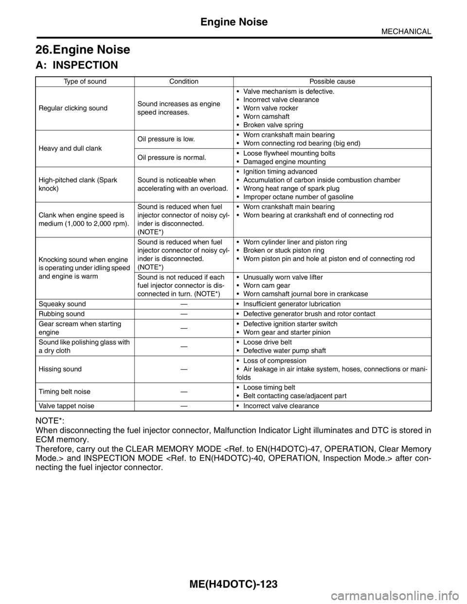
NOTE*:
When disconnecting the fuel injector connector, Malfunction Indicator Light illuminates and DTC is stored in
ECM memory.
Therefore, carry out the CLEAR MEMORY MODE
necting the fuel injector connector.
Type of sound Condition Possible cause
Regular clicking soundSound increases as engine
speed increases. Valve mechanism is defective.
Incorrect valve clearance
Worn valve rocker
Worn camshaft
Broken valve spring
Heavy and dull clankOil pressure is low. Worn crankshaft main bearing
Worn connecting rod bearing (big end)
Oil pressure is normal. Loose flywheel mounting bolts
Damaged engine mounting
High-pitched clank (Spark
knock)Sound is noticeable when
accelerating with an overload. Ignition timing advanced
Accumulation of carbon inside combustion chamber
Wrong heat range of spark plug
Improper octane number of gasoline
Clank when engine speed is
medium (1,000 to 2,000 rpm).Sound is reduced when fuel
injector connector of noisy cyl-
inder is disconnected.
(NOTE*) Worn crankshaft main bearing
Worn bearing at crankshaft end of connecting rod
Knocking sound when engine
is operating under idling speed
and engine is warmSound is reduced when fuel
injector connector of noisy cyl-
inder is disconnected.
(NOTE*) Worn cylinder liner and piston ring
Broken or stuck piston ring
Worn piston pin and hole at piston end of connecting rod
Sound is not reduced if each
fuel injector connector is dis-
connected in turn. (NOTE*) Unusually worn valve lifter
Worn cam gear
Worn camshaft journal bore in crankcase
Squeaky sound — Insufficient generator lubrication
Rubbing sound — Defective generator brush and rotor contact
Gear scream when starting
engine— Defective ignition starter switch
Worn gear and starter pinion
Sound like polishing glass with
a dry cloth— Loose drive belt
Defective water pump shaft
Hissing sound — Loss of compression
Air leakage in air intake system, hoses, connections or mani-
folds
Timing belt noise — Loose timing belt
Belt contacting case/adjacent part
Valve tappet noise — Incorrect valve clearance
Page 1655 of 2870
EN(H4DOTC)-25
ENGINE (DIAGNOSTIC)
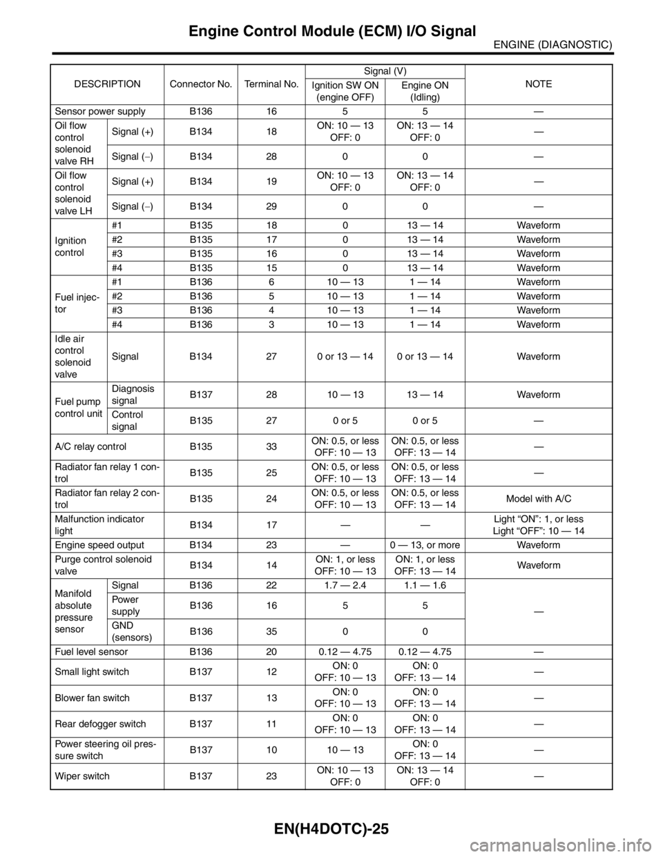
Engine Control Module (ECM) I/O Signal
Sensor power supply B136 16 5 5 —
Oil flow
control
solenoid
valve RHSignal (+) B134 18ON: 10 — 13
OFF: 0ON: 13 — 14
OFF: 0—
Signal (−) B134 28 0 0 —
Oil flow
control
solenoid
valve LHSignal (+) B134 19ON: 10 — 13
OFF: 0ON: 13 — 14
OFF: 0—
Signal (−) B134 29 0 0 —
Ignition
control#1 B135 18 0 13 — 14 Waveform
#2 B135 17 0 13 — 14 Waveform
#3 B135 16 0 13 — 14 Waveform
#4 B135 15 0 13 — 14 Waveform
Fuel injec-
tor#1 B136 6 10 — 13 1 — 14 Waveform
#2 B136 5 10 — 13 1 — 14 Waveform
#3 B136 4 10 — 13 1 — 14 Waveform
#4 B136 3 10 — 13 1 — 14 Waveform
Idle air
control
solenoid
valveSignal B134 27 0 or 13 — 14 0 or 13 — 14 Waveform
Fuel pump
control unitDiagnosis
signalB137 28 10 — 13 13 — 14 Waveform
Control
signalB135 27 0 or 5 0 or 5 —
A/C relay control B135 33ON: 0.5, or less
OFF: 10 — 13ON: 0.5, or less
OFF: 13 — 14—
Radiator fan relay 1 con-
trolB135 25ON: 0.5, or less
OFF: 10 — 13ON: 0.5, or less
OFF: 13 — 14—
Radiator fan relay 2 con-
trolB135 24ON: 0.5, or less
OFF: 10 — 13ON: 0.5, or less
OFF: 13 — 14Model with A/C
Malfunction indicator
lightB134 17 — —Light “ON”: 1, or less
Light “OFF”: 10 — 14
Engine speed output B134 23 — 0 — 13, or more Waveform
Purge control solenoid
valveB134 14ON: 1, or less
OFF: 10 — 13ON: 1, or less
OFF: 13 — 14Wavefor m
Manifold
absolute
pressure
sensorSignal B136 22 1.7 — 2.4 1.1 — 1.6
— Pow er
supplyB136 16 5 5
GND
(sensors)B136 35 0 0
Fuel level sensor B136 20 0.12 — 4.75 0.12 — 4.75 —
Small light switch B137 12ON: 0
OFF: 10 — 13ON: 0
OFF: 13 — 14—
Blower fan switch B137 13ON: 0
OFF: 10 — 13ON: 0
OFF: 13 — 14—
Rear defogger switch B137 11ON: 0
OFF: 10 — 13ON: 0
OFF: 13 — 14—
Power steering oil pres-
sure switchB137 10 10 — 13ON: 0
OFF: 13 — 14—
Wiper switch B137 23ON: 10 — 13
OFF: 0ON: 13 — 14
OFF: 0— DESCRIPTION Connector No. Terminal No.Signal (V)
NOTE
Ignition SW ON
(engine OFF)Engine ON
(Idling)
Page 1664 of 2870

EN(H4DOTC)-34
ENGINE (DIAGNOSTIC)
Subaru Select Monitor
4. READ CURRENT DATA FOR ENGINE. (NORMAL MODE)
1) On the «Main Menu» display screen, select the {Each System Check} and press the [YES] key.
2) On the «System Selection Menu» display screen, select the {Engine} and press the [YES] key.
3) Press the [YES] key after the information of engine type was displayed.
4) On the «Engine Diagnosis» screen, select the {Current Data Display/Save}, and then press the [YES] key.
5) On the «Data Display Menu» screen, select the {Data Display} and press the [YES] key.
6) Using the scroll key, move the display screen up or down until the desired data is shown.
A list of the support data is shown in the following table.
Remarks Display Unit of measure
Battery voltage Battery Voltage V
Vehicle speed signal Vehicle Speed km/h or MPH
Engine speed signal Engine Speed rpm
Engine coolant temperature signal Coolant Temp.°C or °F
Ignition timing signal Ignition Timing deg
Throttle position signal Throttle Opening Angle %
Throttle position signal Throttle Sensor Voltage V
Injection pulse width Fuel Injection #1 Pulse ms
Idle air control signal ISC Valve Duty Ratio %
generated duty control signal ALT Duty %
Fuel pump duty control signal Fuel Pump Duty %
A/F sensor current A/F Sensor #1 Current mA
A/F sensor resistance A/F Sensor #1 ResistanceΩ
Front oxygen (A/F) sensor output signal A/F Sensor #1 —
Rear oxygen sensor output signalRear O
2 Sensor
V
Short term fuel trim A/F Correction #1 %
Knock sensor correction Knocking Correction deg
Atmospheric pressure signal Atmosphere Pressure mmHg, kPa, inHg or psi
Intake manifold relative pressure signal Mani. Relative Pressure mmHg, kPa, inHg or psi
Intake manifold absolute pressure signal Mani. Absolute Pressure mmHg, kPa, inHg or psi
A/F correction (short term fuel trim) by rear oxygen sensor A/F Correction #3 %
Long term whole fuel trim A/F Learning #1 %
Canister purge control solenoid valve duty ratio CPC Valve Duty Ratio %
Primary supercharged pressure control signal Primary Control %
Tumble generated valve position sensor signal (RH side) TGV Position Sensor R V
Tumble generated valve position sensor signal (LH side) TGV Position Sensor L V
Tumble generated valve drive signal TGV Drive OPEN or CLOSE
Fuel level signal Fuel Level Voltage V
Intake air temperature signal Intake Air Temp.°C or °F
Mass air flow sensor signal Mass Air Flow g/s
Mass air flow sensor signal Air Flow Sensor Voltage V
Valve Timing Signal VVT Adv. Ang. amount R deg
Valve Timing Signal VVT Adv. Ang. amount L deg
Oil flow control solenoid valve signal OCV Duty R %
Oil flow control solenoid valve signal OCV Duty L %
Oil flow control solenoid valve current OCV current R mA
Oil flow control solenoid valve current OCV Current L mA
AT/MT identification signal AT Vehicle ID Signal AT or MT
Test Mode Signal Test Mode Signal ON or OFF
Load switch signal Electric Load Signal ON or OFF
Ignition switch signal Ignition Switch ON or OFF
Neutral position switch signal Neutral Position Switch ON or OFF
Air conditioning switch signal A/C Switch ON or OFF
Page 1665 of 2870
EN(H4DOTC)-35
ENGINE (DIAGNOSTIC)
Subaru Select Monitor
NOTE:
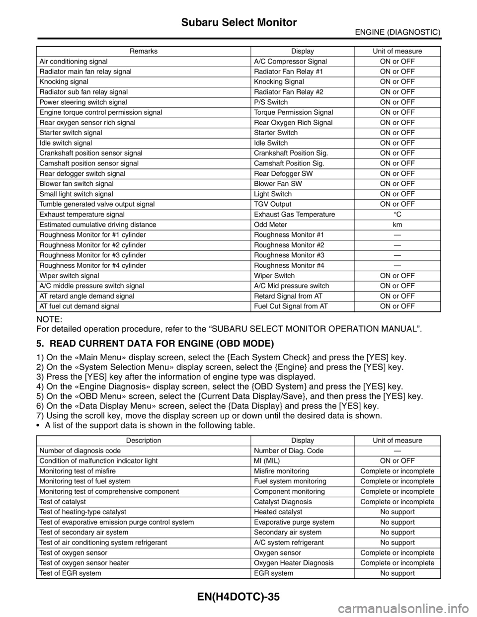
For detailed operation procedure, refer to the “SUBARU SELECT MONITOR OPERATION MANUAL”.
5. READ CURRENT DATA FOR ENGINE (OBD MODE)
1) On the «Main Menu» display screen, select the {Each System Check} and press the [YES] key.
2) On the «System Selection Menu» display screen, select the {Engine} and press the [YES] key.
3) Press the [YES] key after the information of engine type was displayed.
4) On the «Engine Diagnosis» display screen, select the {OBD System} and press the [YES] key.
5) On the «OBD Menu» screen, select the {Current Data Display/Save}, and then press the [YES] key.
6) On the «Data Display Menu» screen, select the {Data Display} and press the [YES] key.
7) Using the scroll key, move the display screen up or down until the desired data is shown.
A list of the support data is shown in the following table.
Air conditioning signal A/C Compressor Signal ON or OFF
Radiator main fan relay signal Radiator Fan Relay #1 ON or OFF
Knocking signal Knocking Signal ON or OFF
Radiator sub fan relay signal Radiator Fan Relay #2 ON or OFF
Power steering switch signal P/S Switch ON or OFF
Engine torque control permission signal Torque Permission Signal ON or OFF
Rear oxygen sensor rich signal Rear Oxygen Rich Signal ON or OFF
Starter switch signal Starter Switch ON or OFF
Idle switch signal Idle Switch ON or OFF
Crankshaft position sensor signal Crankshaft Position Sig. ON or OFF
Camshaft position sensor signal Camshaft Position Sig. ON or OFF
Rear defogger switch signal Rear Defogger SW ON or OFF
Blower fan switch signal Blower Fan SW ON or OFF
Small light switch signal Light Switch ON or OFF
Tumble generated valve output signal TGV Output ON or OFF
Exhaust temperature signal Exhaust Gas Temperature°C
Estimated cumulative driving distance Odd Meter km
Roughness Monitor for #1 cylinder Roughness Monitor #1 —
Roughness Monitor for #2 cylinder Roughness Monitor #2 —
Roughness Monitor for #3 cylinder Roughness Monitor #3 —
Roughness Monitor for #4 cylinder Roughness Monitor #4 —
Wiper switch signal Wiper Switch ON or OFF
A/C middle pressure switch signal A/C Mid pressure switch ON or OFF
AT retard angle demand signal Retard Signal from AT ON or OFF
AT fuel cut demand signal Fuel Cut Signal from AT ON or OFF
Description Display Unit of measure
Number of diagnosis code Number of Diag. Code —
Condition of malfunction indicator light MI (MIL) ON or OFF
Monitoring test of misfire Misfire monitoring Complete or incomplete
Monitoring test of fuel system Fuel system monitoring Complete or incomplete
Monitoring test of comprehensive component Component monitoring Complete or incomplete
Test of catalyst Catalyst Diagnosis Complete or incomplete
Test of heating-type catalyst Heated catalyst No support
Test of evaporative emission purge control system Evaporative purge system No support
Test of secondary air system Secondary air system No support
Test of air conditioning system refrigerant A/C system refrigerant No support
Test of oxygen sensor Oxygen sensor Complete or incomplete
Test of oxygen sensor heater Oxygen Heater Diagnosis Complete or incomplete
Test of EGR system EGR system No supportRemarks Display Unit of measure