replace SUBARU FORESTER 2004 Service Repair Manual
[x] Cancel search | Manufacturer: SUBARU, Model Year: 2004, Model line: FORESTER, Model: SUBARU FORESTER 2004Pages: 2870, PDF Size: 38.67 MB
Page 655 of 2870
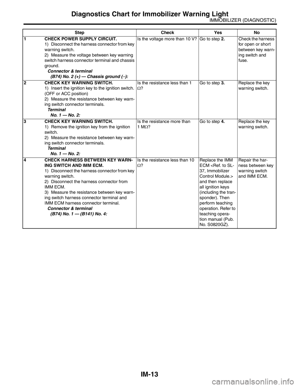
IM-13
IMMOBILIZER (DIAGNOSTIC)
Diagnostics Chart for Immobilizer Warning Light
Step Check Yes No
1 CHECK POWER SUPPLY CIRCUIT.
1) Disconnect the harness connector from key
warning switch.
2) Measure the voltage between key warning
switch harness connector terminal and chassis
ground.
Connector & terminal
(B74) No. 2 (+) — Chassis ground (
−):Is the voltage more than 10 V? Go to step 2.Check the harness
for open or short
between key warn-
ing switch and
fuse.
2 CHECK KEY WARNING SWITCH.
1) Insert the ignition key to the ignition switch.
(OFF or ACC position)
2) Measure the resistance between key warn-
ing switch connector terminals.
Te r m i n a l
No. 1 — No. 2:Is the resistance less than 1
Ω?Go to step 3.Replace the key
warning switch.
3 CHECK KEY WARNING SWITCH.
1) Remove the ignition key from the ignition
switch.
2) Measure the resistance between key warn-
ing switch connector terminals.
Te r m i n a l
No. 1 — No. 2:Is the resistance more than
1 MΩ?Go to step 4.Replace the key
warning switch.
4 CHECK HARNESS BETWEEN KEY WARN-
ING SWITCH AND IMM ECM.
1) Disconnect the harness connector from key
warning switch.
2) Disconnect the harness connector from
IMM ECM.
3) Measure the resistance between key warn-
ing switch harness connector terminal and
IMM ECM harness connector terminal.
Connector & terminal
(B74) No. 1 — (B141) No. 4:Is the resistance less than 10
Ω?Replace the IMM
ECM
Control Module.>
and then replace
all ignition keys
(including the tran-
sponder). Then
perform teaching
operation. Refer to
teaching opera-
tion manual (Pub.
No. S0820GZ).Repair the har-
ness between key
warning switch
and IMM ECM.
Page 657 of 2870
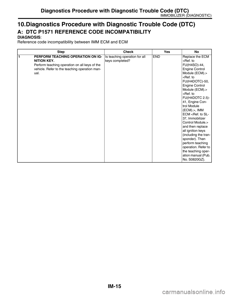
IM-15
IMMOBILIZER (DIAGNOSTIC)
Diagnostics Procedure with Diagnostic Trouble Code (DTC)
10.Diagnostics Procedure with Diagnostic Trouble Code (DTC)
A: DTC P1571 REFERENCE CODE INCOMPATIBILITY
DIAGNOSIS:
Reference code incompatibility between IMM ECM and ECM
Step Check Yes No
1 PERFORM TEACHING OPERATION ON IG-
NITION KEY.
Perform teaching operation on all keys of the
vehicle. Refer to the teaching operation man-
ual.Is teaching operation for all
keys completed?END Replace the ECM
Engine Control
Module (ECM).>
Engine Control
Module (ECM).>
41, Engine Con-
trol Module
(ECM).>, IMM
ECM
Control Module.>
and then replace
all ignition keys
(including the tran-
sponder). Then
perform teaching
operation. Refer to
the teaching oper-
ation manual (Pub.
No. S0820GZ).
Page 660 of 2870
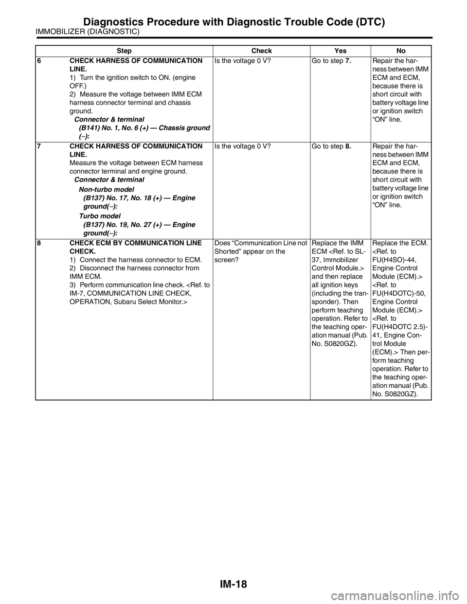
IM-18
IMMOBILIZER (DIAGNOSTIC)
Diagnostics Procedure with Diagnostic Trouble Code (DTC)
6 CHECK HARNESS OF COMMUNICATION
LINE.
1) Turn the ignition switch to ON. (engine
OFF.)
2) Measure the voltage between IMM ECM
harness connector terminal and chassis
ground.
Connector & terminal
(B141) No. 1, No. 6 (+) — Chassis ground
(
−):Is the voltage 0 V? Go to step 7.Repair the har-
ness between IMM
ECM and ECM,
because there is
short circuit with
battery voltage line
or ignition switch
“ON” line.
7 CHECK HARNESS OF COMMUNICATION
LINE.
Measure the voltage between ECM harness
connector terminal and engine ground.
Connector & terminal
Non-turbo model
(B137) No. 17, No. 18 (+) — Engine
ground(
−):
Turbo model
(B137) No. 19, No. 27 (+) — Engine
ground(
−):Is the voltage 0 V? Go to step 8.Repair the har-
ness between IMM
ECM and ECM,
because there is
short circuit with
battery voltage line
or ignition switch
“ON” line.
8 CHECK ECM BY COMMUNICATION LINE
CHECK.
1) Connect the harness connector to ECM.
2) Disconnect the harness connector from
IMM ECM.
3) Perform communication line check.
OPERATION, Subaru Select Monitor.>Does “Communication Line not
Shorted” appear on the
screen?Replace the IMM
ECM
Control Module.>
and then replace
all ignition keys
(including the tran-
sponder). Then
perform teaching
operation. Refer to
the teaching oper-
ation manual (Pub.
No. S0820GZ).Replace the ECM.
Engine Control
Module (ECM).>
Engine Control
Module (ECM).>
41, Engine Con-
trol Module
(ECM).> Then per-
form teaching
operation. Refer to
the teaching oper-
ation manual (Pub.
No. S0820GZ). Step Check Yes No
Page 661 of 2870
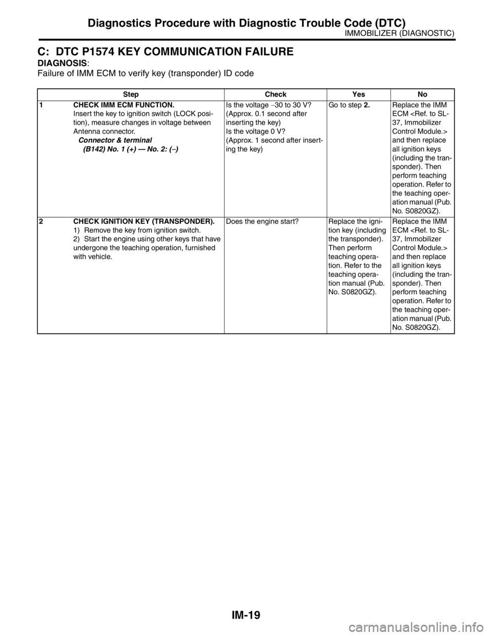
IM-19
IMMOBILIZER (DIAGNOSTIC)
Diagnostics Procedure with Diagnostic Trouble Code (DTC)
C: DTC P1574 KEY COMMUNICATION FAILURE
DIAGNOSIS:
Failure of IMM ECM to verify key (transponder) ID code
Step Check Yes No
1 CHECK IMM ECM FUNCTION.
Insert the key to ignition switch (LOCK posi-
tion), measure changes in voltage between
Antenna connector.
Connector & terminal
(B142) No. 1 (+) — No. 2: (
−)Is the voltage −30 to 30 V?
(Approx. 0.1 second after
inserting the key)
Is the voltage 0 V?
(Approx. 1 second after insert-
ing the key)Go to step 2.Replace the IMM
ECM
Control Module.>
and then replace
all ignition keys
(including the tran-
sponder). Then
perform teaching
operation. Refer to
the teaching oper-
ation manual (Pub.
No. S0820GZ).
2 CHECK IGNITION KEY (TRANSPONDER).
1) Remove the key from ignition switch.
2) Start the engine using other keys that have
undergone the teaching operation, furnished
with vehicle.Does the engine start? Replace the igni-
tion key (including
the transponder).
Then perform
teaching opera-
tion. Refer to the
teaching opera-
tion manual (Pub.
No. S0820GZ).Replace the IMM
ECM
Control Module.>
and then replace
all ignition keys
(including the tran-
sponder). Then
perform teaching
operation. Refer to
the teaching oper-
ation manual (Pub.
No. S0820GZ).
Page 662 of 2870
IM-20
IMMOBILIZER (DIAGNOSTIC)
Diagnostics Procedure with Diagnostic Trouble Code (DTC)
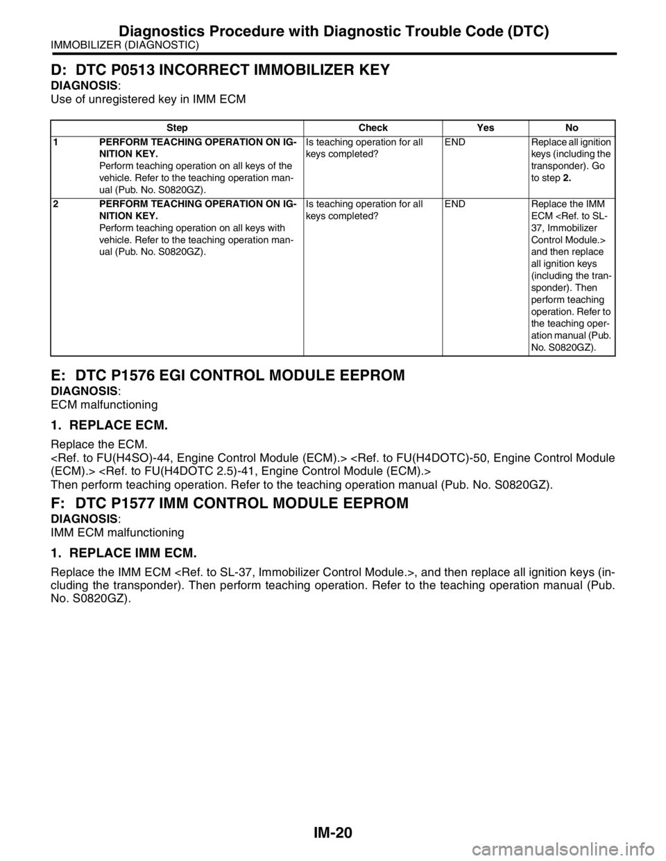
D: DTC P0513 INCORRECT IMMOBILIZER KEY
DIAGNOSIS:
Use of unregistered key in IMM ECM
E: DTC P1576 EGI CONTROL MODULE EEPROM
DIAGNOSIS:
ECM malfunctioning
1. REPLACE ECM.
Replace the ECM.
Then perform teaching operation. Refer to the teaching operation manual (Pub. No. S0820GZ).
F: DTC P1577 IMM CONTROL MODULE EEPROM
DIAGNOSIS:
IMM ECM malfunctioning
1. REPLACE IMM ECM.
Replace the IMM ECM
cluding the transponder). Then perform teaching operation. Refer to the teaching operation manual (Pub.
No. S0820GZ).
Step Check Yes No
1 PERFORM TEACHING OPERATION ON IG-
NITION KEY.
Perform teaching operation on all keys of the
vehicle. Refer to the teaching operation man-
ual (Pub. No. S0820GZ).Is teaching operation for all
keys completed?END Replace all ignition
keys (including the
transponder). Go
to step 2.
2 PERFORM TEACHING OPERATION ON IG-
NITION KEY.
Perform teaching operation on all keys with
vehicle. Refer to the teaching operation man-
ual (Pub. No. S0820GZ).Is teaching operation for all
keys completed?END Replace the IMM
ECM
Control Module.>
and then replace
all ignition keys
(including the tran-
sponder). Then
perform teaching
operation. Refer to
the teaching oper-
ation manual (Pub.
No. S0820GZ).
Page 664 of 2870
IM-22
IMMOBILIZER (DIAGNOSTIC)
Diagnostics Procedure with Diagnostic Trouble Code (DTC)
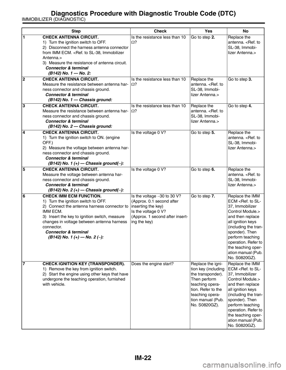
Step Check Yes No
1 CHECK ANTENNA CIRCUIT.
1) Turn the ignition switch to OFF.
2) Disconnect the harness antenna connector
from IMM ECM.
3) Measure the resistance of antenna circuit.
Connector & terminal
(B142) No. 1 — No. 2:Is the resistance less than 10
Ω?Go to step 2.Replace the
antenna.
lizer Antenna.>
2 CHECK ANTENNA CIRCUIT.
Measure the resistance between antenna har-
ness connector and chassis ground.
Connector & terminal
(B142) No. 1 — Chassis ground:Is the resistance less than 10
Ω?Replace the
antenna.
lizer Antenna.>Go to step 3.
3 CHECK ANTENNA CIRCUIT.
Measure the resistance between antenna har-
ness connector and chassis ground.
Connector & terminal
(B142) No. 2 — Chassis ground:Is the resistance less than 10
Ω?Replace the
antenna.
lizer Antenna.>Go to step 4.
4 CHECK ANTENNA CIRCUIT.
1) Turn the ignition switch to ON. (engine
OFF.)
2) Measure the voltage between antenna har-
ness connector and chassis ground.
Connector & terminal
(B142) No. 1 (+) — Chassis ground(
−):Is the voltage 0 V? Go to step 5.Replace the
antenna.
lizer Antenna.>
5 CHECK ANTENNA CIRCUIT.
Measure the voltage between antenna har-
ness connector and chassis ground.
Connector & terminal
(B142) No. 2 (+) — Chassis ground(
−):Is the voltage 0 V? Go to step 6.Replace the
antenna.
lizer Antenna.>
6 CHECK IMM ECM FUNCTION.
1) Turn the ignition switch to OFF.
2) Connect the antenna harness connector to
IMM ECM.
3) Insert the key to ignition switch, measure
changes in voltage between antenna harness
connector.
Connector & terminal
(B142) No. 1 (+) — No. 2 (
−):Is the voltage −30 to 30 V?
(Approx. 0.1 second after
inserting the key)
Is the voltage 0 V?
(Approx. 1 second after insert-
ing the key)Go to step 7.Replace the IMM
ECM
Control Module.>
and then replace
all ignition keys
(including the tran-
sponder). Then
perform teaching
operation. Refer to
the teaching oper-
ation manual (Pub.
No. S0820GZ).
7 CHECK IGNITION KEY (TRANSPONDER).
1) Remove the key from ignition switch.
2) Start the engine using other keys that have
undergone the teaching operation, furnished
with vehicle.Does the engine start? Replace the igni-
tion key (including
the transponder).
Then perform
teaching opera-
tion. Refer to the
teaching opera-
tion manual (Pub.
No. S0820GZ).Replace the IMM
ECM
Control Module.>
and then replace
all ignition keys
(including the tran-
sponder). Then
perform teaching
operation. Refer to
the teaching oper-
ation manual (Pub.
No. S0820GZ).
Page 665 of 2870
FUJI HEAVY INDUSTRIES LTD. G8080GE6
2004 FORESTER SERVICE MANUAL QUICK REFERENCE INDEX
CHASSIS SECTION
This service manual has been prepared
to provide SUBARU service personnel
with the necessary information and data
for the correct maintenance and repair
of SUBARU vehicles.
This manual includes the procedures
for maintenance, disassembling, reas-
sembling, inspection and adjustment of
components and diagnostics for guid-
ance of experienced mechanics.
Please peruse and utilize this manual
fully to ensure complete repair work for
satisfying our customers by keeping
their vehicle in optimum condition.
When replacement of parts during
repair work is needed, be sure to use
SUBARU genuine parts.
All information, illustration and specifi-
cations contained in this manual are
based on the latest product information
available at the time of publication
approval.FRONT SUSPENSION FS
REAR SUSPENSION RS
WHEEL AND TIRE SYSTEM WT
DIFFERENTIAL DI
TRANSFER CASE TC
DRIVE SHAFT SYSTEM DS
ABS ABS
ABS (DIAGNOSTIC) ABS
BRAKE BR
PARKING BRAKE PB
POWER ASSISTED SYSTEM
(POWER STEERING)PS
Page 680 of 2870

FUJI HEAVY INDUSTRIES LTD. G8080GE1
2004 FORESTER SERVICE MANUAL QUICK REFERENCE INDEX
GENERAL INFORMATION
SECTION
This service manual has been prepared
to provide SUBARU service personnel
with the necessary information and data
for the correct maintenance and repair
of SUBARU vehicles.
This manual includes the procedures
for maintenance, disassembling, reas-
sembling, inspection and adjustment of
components and diagnostics for guid-
ance of experienced mechanics.
Please peruse and utilize this manual
fully to ensure complete repair work for
satisfying our customers by keeping
their vehicle in optimum condition.
When replacement of parts during
repair work is needed, be sure to use
SUBARU genuine parts.
All information, illustration and specifi-
cations contained in this manual are
based on the latest product information
available at the time of publication
approval.FOREWORD FW
HOW TO USE THIS MANUAL HU
SPECIFICATION SPC
PRECAUTION PC
NOTE NT
IDENTIFICATION ID
RECOMMENDED MATERIAL RM
PRE-DELIVERY INSPECTION PI
PERIODIC MAINTENANCE SERVICE PM
Page 686 of 2870
HU-3
HOW TO USE THIS MANUAL
How to Use This Manual
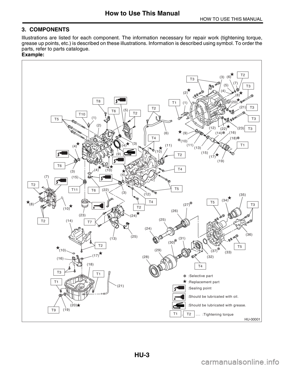
3. COMPONENTS
Illustrations are listed for each component. The information necessary for repair work (tightening torque,
grease up points, etc.) is described on these illustrations. Information is described using symbol. To order the
parts, refer to parts catalogue.
Example:
HU-00001
(14)
(9)
(8)(7)(6)
(10)
(4)
(10)
(22)(11)
(19) (17) (15) (13)(12)
(18) (16) (1)(2)(3)
(4)(5)(6)
(7)
(8)
(11) (10)(9)
(12)
(13)
(19)(18)
(20)(17)
(16)(24)
(10)(25) (5)
(4)
(4)
(4)(3)
(3)
(3) (2) (1)
(21) (15)
(23)
T7
T2
T2
T2
T2
T2
T2
T4
T5
T5
T8
T6
T6
T6T11
T10
T1
T1
T3
T3
T3
T1
T9
T4
T5
T5T3
T4
T3T2
T4
T2
T1
T3
(20)
(21)
(23)
(22)
(10)
(24)(25)(26)(35)
(34)
(27)
(14)
(28)
(29)
(31)
(32)(37)(30)
(33)
(36)
T3
T2T1:Selective part
:Replacement part
:Should be lubricated with grease. :Should be lubricated with oil.:Sealing point
:Tightening torque .... ,
Page 728 of 2870
PI-5
PRE-DELIVERY INSPECTION
Pre-delivery Inspection
1. APPEARANCE CHECK
1) If the vehicle is covered with protective coating,
visually check the vehicle body for damage and
dents.
2) If there is no protective coating, check the body
paints for small areas of damage or stains and re-
pair as necessary.
3) Check the window glass, door glass, and lights
for any cracks or damage and repair or replace the
parts as necessary.
4) Check the plated parts, such as the grilles and
door knobs, for damage or loss of gloss and repair
or replace the parts as necessary.
2. TIRE CHECK
Check the tire outer faces for any damage.
Check the tire air pressure by referring to the fol-
lowing table.
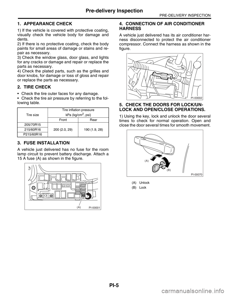
3. FUSE INSTALLATION
A vehicle just delivered has no fuse for the room
lamp circuit to prevent battery discharge. Attach a
15 A fuse (A) as shown in the figure.
4. CONNECTION OF AIR CONDITIONER
HARNESS
A vehicle just delivered has its air conditioner har-
ness disconnected to protect the air conditioner
compressor. Connect the harness as shown in the
figure.
5. CHECK THE DOORS FOR LOCK/UN-
LOCK AND OPEN/CLOSE OPERATIONS.
1) Using the key, lock and unlock the door several
times to check for normal operation. Open and
close the door several times for smooth movement.Tire sizeTire inflation pressure
kPa (kg/cm2, psi)
Front Rear
205/70R15
200 (2.0, 29) 190 (1.9, 28) 215/60R16
P215/60R16
PI-00001(A)
(A) Unlock
(B) Lock
PI-00002
PI-00070
(A)
(B)