SUBARU FORESTER 2004 Service Repair Manual
Manufacturer: SUBARU, Model Year: 2004, Model line: FORESTER, Model: SUBARU FORESTER 2004Pages: 2870, PDF Size: 38.67 MB
Page 2361 of 2870
FUJI HEAVY INDUSTRIES LTD. G8080GE5
2004 FORESTER SERVICE MANUAL QUICK REFERENCE INDEX
TRANSMISSION SECTION
This service manual has been prepared
to provide SUBARU service personnel
with the necessary information and data
for the correct maintenance and repair
of SUBARU vehicles.
This manual includes the procedures
for maintenance, disassembling, reas-
sembling, inspection and adjustment of
components and diagnostics for guid-
ance of experienced mechanics.
Please peruse and utilize this manual
fully to ensure complete repair work for
satisfying our customers by keeping
their vehicle in optimum condition.
When replacement of parts during
repair work is needed, be sure to use
SUBARU genuine parts.
All information, illustration and specifi-
cations contained in this manual are
based on the latest product information
available at the time of publication
approval.CONTROL SYSTEM CS
AUTOMATIC TRANSMISSION 4AT
AUTOMATIC TRANSMISSION
(DIAGNOSTIC)4AT(H4SO)
AUTOMATIC TRANSMISSION
(DIAGNOSTIC)4AT(H4DOTC)
AUTOMATIC TRANSMISSION
(DIAGNOSTIC)4AT(H4DOTC 2.5)
MANUAL TRANSMISSION AND
DIFFERENTIAL5MT
CLUTCH SYSTEM CL
Page 2362 of 2870
4AT-49
AUTOMATIC TRANSMISSION
Extension Case Oil Seal
11.Extension Case Oil Seal
A: INSPECTION
Make sure that the ATF does not leak from the joint
of transmission and propeller shaft. If so, replace
the oil seal.
B: REPLACEMENT
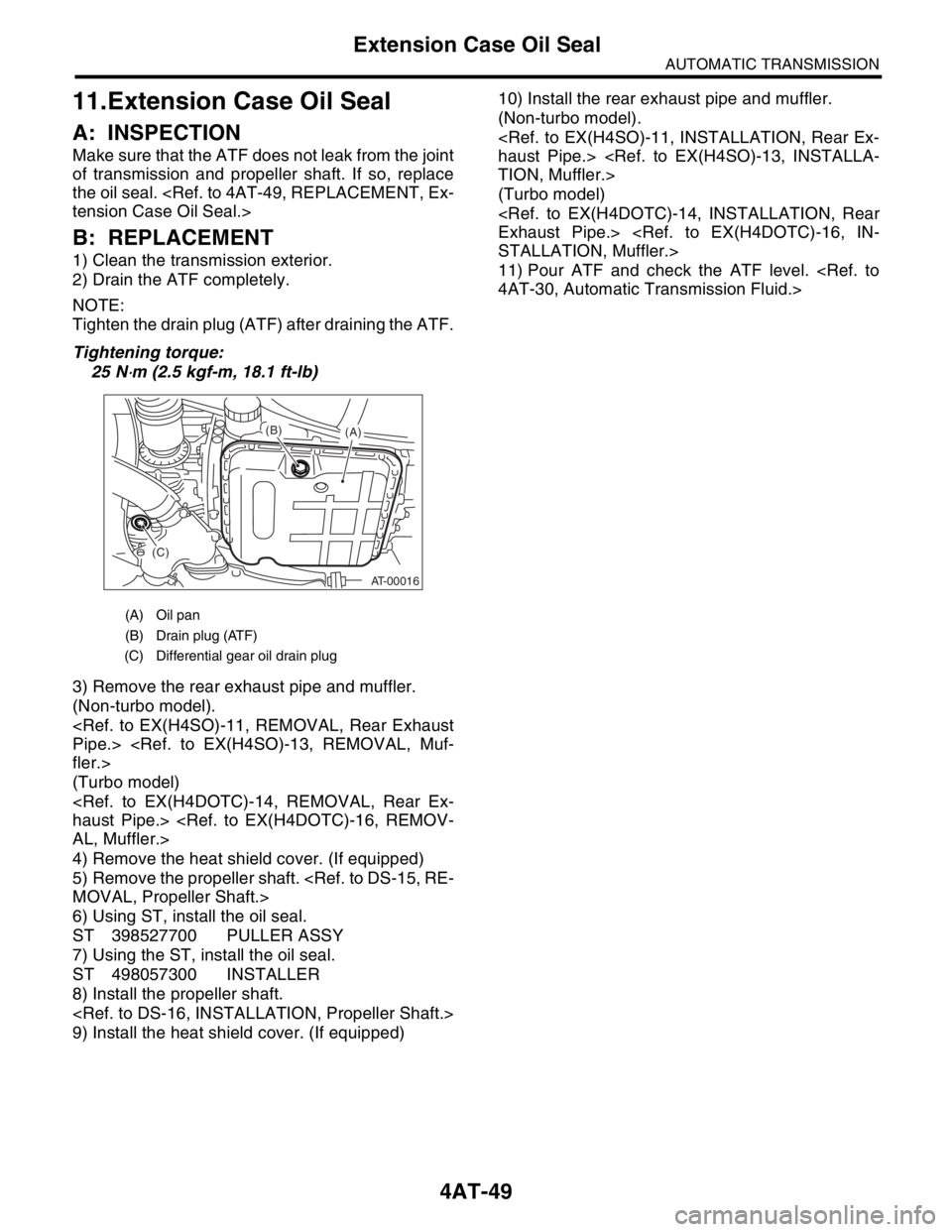
1) Clean the transmission exterior.
2) Drain the ATF completely.
NOTE:
Tighten the drain plug (ATF) after draining the ATF.
Tightening torque:
25 N
⋅m (2.5 kgf-m, 18.1 ft-lb)
3) Remove the rear exhaust pipe and muffler.
(Non-turbo model).
(Turbo model)
4) Remove the heat shield cover. (If equipped)
5) Remove the propeller shaft.
6) Using ST, install the oil seal.
ST 398527700 PULLER ASSY
7) Using the ST, install the oil seal.
ST 498057300 INSTALLER
8) Install the propeller shaft.
9) Install the heat shield cover. (If equipped)10) Install the rear exhaust pipe and muffler.
(Non-turbo model).
(Turbo model)
11) Pour ATF and check the ATF level.
(A) Oil pan
(B) Drain plug (ATF)
(C) Differential gear oil drain plug
AT-00016
(A) (B)
(C)
Page 2363 of 2870
4AT-50
AUTOMATIC TRANSMISSION
Differential Side Retainer Oil Seal
12.Differential Side Retainer Oil
Seal
A: INSPECTION
Check the leakage of gear oil from differential side
retainer oil seal part.
If there is oil leakage, replace the oil seal.
B: REPLACEMENT
1) Lift-up the vehicle.
2) Remove the front exhaust pipe and center ex-
haust pipe.
(Non-turbo model)
(Turbo model)
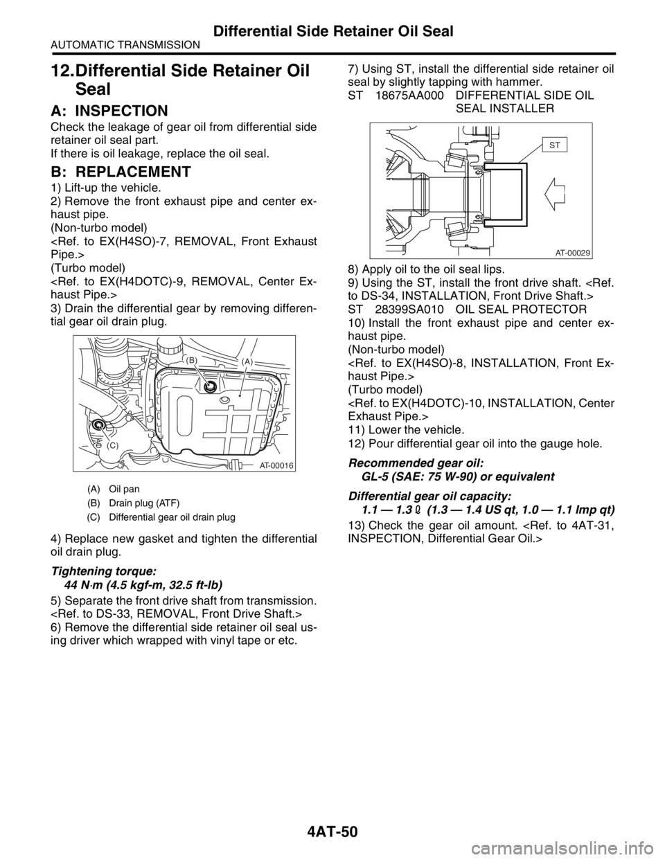
3) Drain the differential gear by removing differen-
tial gear oil drain plug.
4) Replace new gasket and tighten the differential
oil drain plug.
Tightening torque:
44 N
⋅m (4.5 kgf-m, 32.5 ft-lb)
5) Separate the front drive shaft from transmission.
6) Remove the differential side retainer oil seal us-
ing driver which wrapped with vinyl tape or etc.7) Using ST, install the differential side retainer oil
seal by slightly tapping with hammer.
ST 18675AA000 DIFFERENTIAL SIDE OIL
SEAL INSTALLER
8) Apply oil to the oil seal lips.
9) Using the ST, install the front drive shaft.
ST 28399SA010 OIL SEAL PROTECTOR
10) Install the front exhaust pipe and center ex-
haust pipe.
(Non-turbo model)
(Turbo model)
11) Lower the vehicle.
12) Pour differential gear oil into the gauge hole.
Recommended gear oil:
GL-5 (SAE: 75 W-90) or equivalent
Differential gear oil capacity:
1.1 — 1.32 (1.3 — 1.4 US qt, 1.0 — 1.1 Imp qt)
13) Check the gear oil amount.
(A) Oil pan
(B) Drain plug (ATF)
(C) Differential gear oil drain plug
AT-00016
(A) (B)
(C)
AT-00029
ST
Page 2364 of 2870
4AT-51
AUTOMATIC TRANSMISSION
Inhibitor Switch
13.Inhibitor Switch
A: INSPECTION
When the driving condition or starter motor opera-
tion is erroneous, first check the shift linkage for im-
proper operation. If the shift linkage is functioning
properly, check the inhibitor switch.
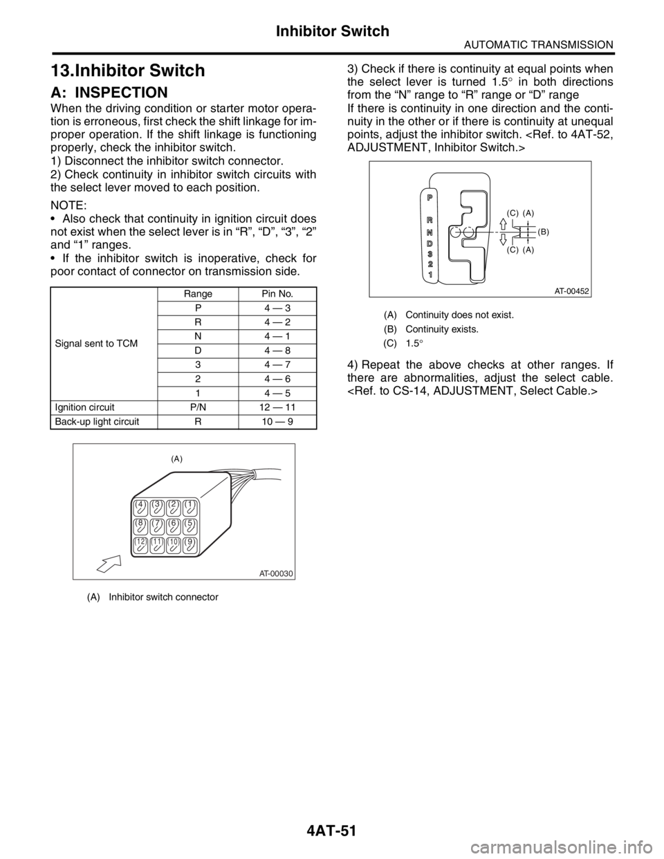
1) Disconnect the inhibitor switch connector.
2) Check continuity in inhibitor switch circuits with
the select lever moved to each position.
NOTE:
Also check that continuity in ignition circuit does
not exist when the select lever is in “R”, “D”, “3”, “2”
and “1” ranges.
If the inhibitor switch is inoperative, check for
poor contact of connector on transmission side.3) Check if there is continuity at equal points when
the select lever is turned 1.5° in both directions
from the “N” range to “R” range or “D” range
If there is continuity in one direction and the conti-
nuity in the other or if there is continuity at unequal
points, adjust the inhibitor switch.
4) Repeat the above checks at other ranges. If
there are abnormalities, adjust the select cable.
Signal sent to TCMRange Pin No.
P4 — 3
R4 — 2
N4 — 1
D4 — 8
34 — 7
24 — 6
14 — 5
Ignition circuit P/N 12 — 11
Back-up light circuit R 10 — 9
(A) Inhibitor switch connector
AT-00030
(4)(3)(2) (1)
(5) (6) (7) (8)
(9)
(10) (11) (12)
(A)
(A) Continuity does not exist.
(B) Continuity exists.
(C) 1.5°
(C) (A) (C) (A)
(B)
AT-00452
P
R
N
D
3
2
1
Page 2365 of 2870
4AT-52
AUTOMATIC TRANSMISSION
Inhibitor Switch
B: ADJUSTMENT
1) Shift the select lever to the “N” range.
2) Loosen the three inhibitor switch assembly se-
curing bolts.
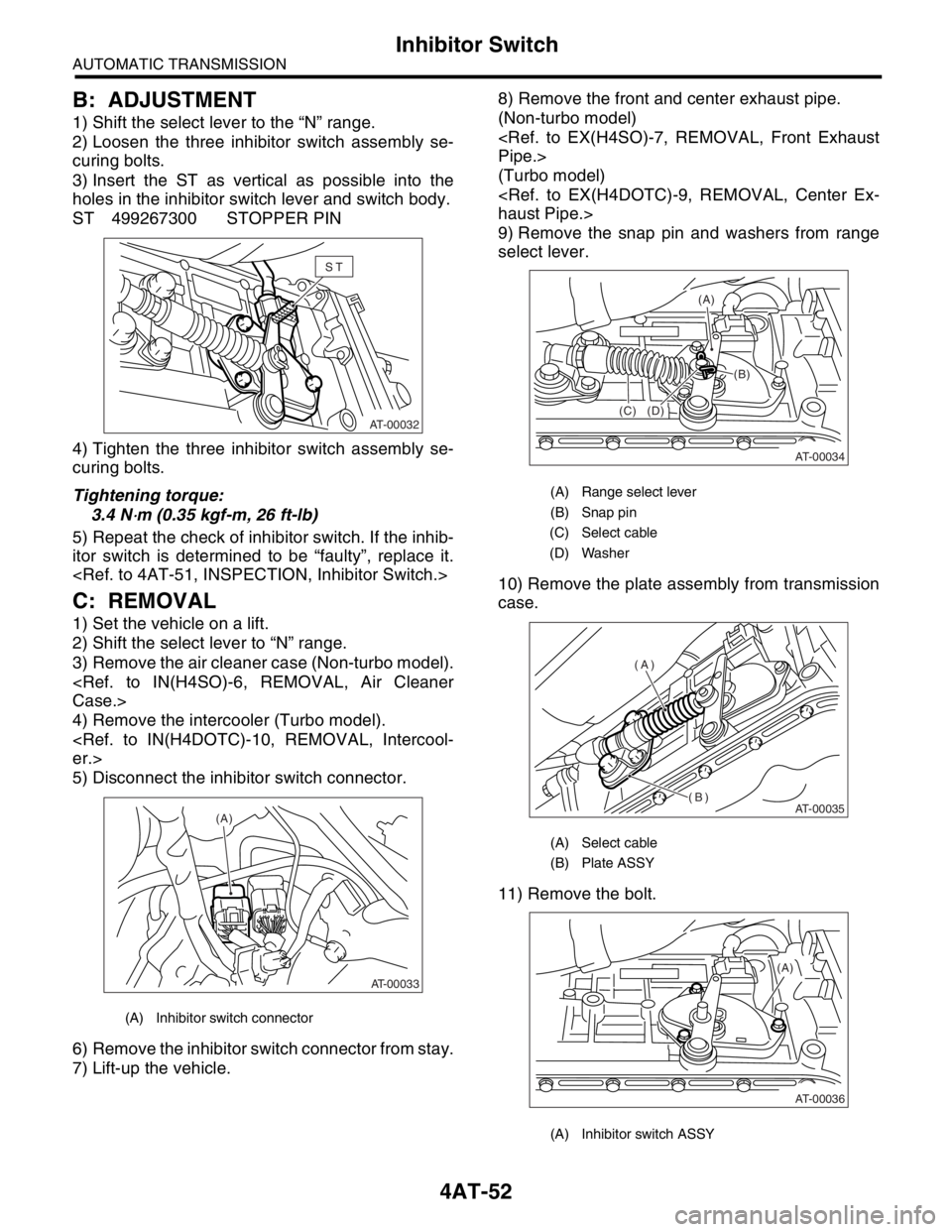
3) Insert the ST as vertical as possible into the
holes in the inhibitor switch lever and switch body.
ST 499267300 STOPPER PIN
4) Tighten the three inhibitor switch assembly se-
curing bolts.
Tightening torque:
3.4 N
⋅m (0.35 kgf-m, 26 ft-lb)
5) Repeat the check of inhibitor switch. If the inhib-
itor switch is determined to be “faulty”, replace it.
C: REMOVAL
1) Set the vehicle on a lift.
2) Shift the select lever to “N” range.
3) Remove the air cleaner case (Non-turbo model).
4) Remove the intercooler (Turbo model).
5) Disconnect the inhibitor switch connector.
6) Remove the inhibitor switch connector from stay.
7) Lift-up the vehicle.8) Remove the front and center exhaust pipe.
(Non-turbo model)
(Turbo model)
9) Remove the snap pin and washers from range
select lever.
10) Remove the plate assembly from transmission
case.
11) Remove the bolt.
(A) Inhibitor switch connector
ST
AT-00032
AT-00033
(A)
(A) Range select lever
(B) Snap pin
(C) Select cable
(D) Washer
(A) Select cable
(B) Plate ASSY
(A) Inhibitor switch ASSY
AT-00034
(C)(B) (A)
(D)
AT-00035
(A)
(B)
(A)
AT-00036
Page 2366 of 2870
4AT-53
AUTOMATIC TRANSMISSION
Inhibitor Switch
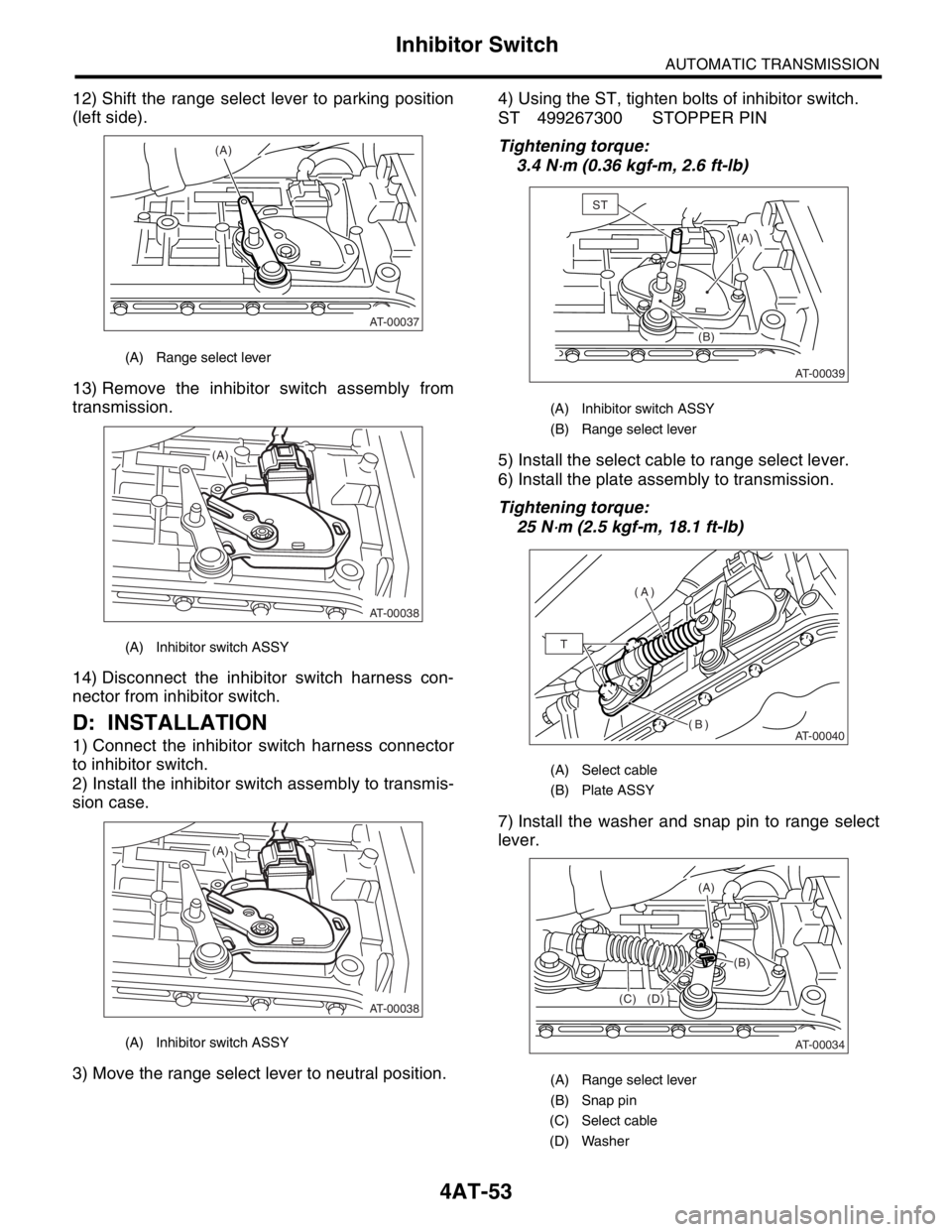
12) Shift the range select lever to parking position
(left side).
13) Remove the inhibitor switch assembly from
transmission.
14) Disconnect the inhibitor switch harness con-
nector from inhibitor switch.
D: INSTALLATION
1) Connect the inhibitor switch harness connector
to inhibitor switch.
2) Install the inhibitor switch assembly to transmis-
sion case.
3) Move the range select lever to neutral position.4) Using the ST, tighten bolts of inhibitor switch.
ST 499267300 STOPPER PIN
Tightening torque:
3.4 N
⋅m (0.36 kgf-m, 2.6 ft-lb)
5) Install the select cable to range select lever.
6) Install the plate assembly to transmission.
Tightening torque:
25 N
⋅m (2.5 kgf-m, 18.1 ft-lb)
7) Install the washer and snap pin to range select
lever.
(A) Range select lever
(A) Inhibitor switch ASSY
(A) Inhibitor switch ASSY
(A)
AT-00037
AT-00038
(A)
AT-00038
(A)
(A) Inhibitor switch ASSY
(B) Range select lever
(A) Select cable
(B) Plate ASSY
(A) Range select lever
(B) Snap pin
(C) Select cable
(D) Washer
(A)
AT-00039
(B)
ST
AT-00040
(A)
(B)
T
AT-00034
(C)(B) (A)
(D)
Page 2367 of 2870

4AT-54
AUTOMATIC TRANSMISSION
Inhibitor Switch
8) Install the front and center exhaust pipe. (Non-
turbo model).
9) Install the center exhaust pipe. (Turbo model)
10) Lower the vehicle.
11) Install the inhibitor switch connector to the stay.
12) Connect the inhibitor switch connector.
13) Install the air cleaner case. (Non-turbo model).
14) Install the intercooler. (Turbo model)
15) Inspect the inhibitor switch.
(A) Inhibitor switch connector
AT-00033
(A)
Page 2368 of 2870
4AT-55
AUTOMATIC TRANSMISSION
Front Vehicle Speed Sensor
14.Front Vehicle Speed Sensor
A: REMOVAL
1) Set the vehicle on a lift.
2) Disconnect the ground cable from battery.
3) Remove the air cleaner case. (Non-turbo mod-
el).
4) Remove the intercooler. (Turbo model)
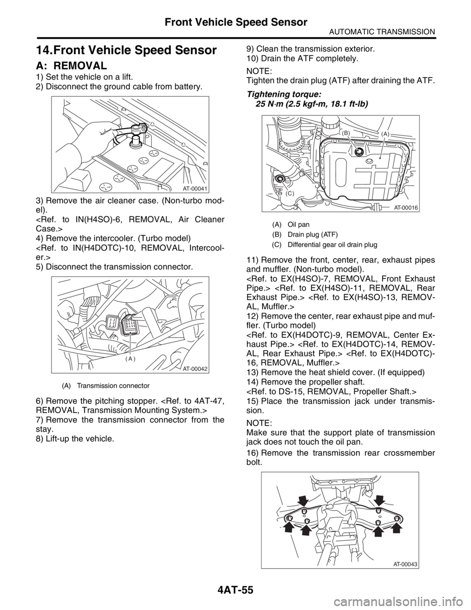
5) Disconnect the transmission connector.
6) Remove the pitching stopper.
7) Remove the transmission connector from the
stay.
8) Lift-up the vehicle.9) Clean the transmission exterior.
10) Drain the ATF completely.
NOTE:
Tighten the drain plug (ATF) after draining the ATF.
Tightening torque:
25 N
⋅m (2.5 kgf-m, 18.1 ft-lb)
11) Remove the front, center, rear, exhaust pipes
and muffler. (Non-turbo model).
12) Remove the center, rear exhaust pipe and muf-
fler. (Turbo model)
13) Remove the heat shield cover. (If equipped)
14) Remove the propeller shaft.
15) Place the transmission jack under transmis-
sion.
NOTE:
Make sure that the support plate of transmission
jack does not touch the oil pan.
16) Remove the transmission rear crossmember
bolt.
(A) Transmission connector
AT-00041
AT-00042
(A)
(A) Oil pan
(B) Drain plug (ATF)
(C) Differential gear oil drain plug
AT-00016
(A) (B)
(C)
AT-00043
Page 2369 of 2870
4AT-56
AUTOMATIC TRANSMISSION
Front Vehicle Speed Sensor
17) Lower the transmission jack.
NOTE:
Do not separate the transmission jack and trans-
mission.
18) Remove the ATF cooler inlet and outlet pipes.
CAUTION:
When removing the outlet pipe, be careful not
to lose the ball and spring used with retaining
screw.
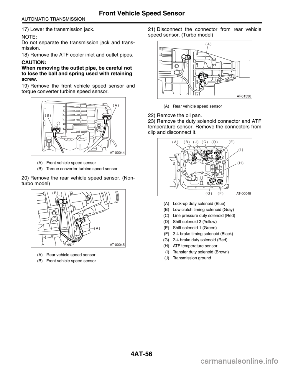
19) Remove the front vehicle speed sensor and
torque converter turbine speed sensor.
20) Remove the rear vehicle speed sensor. (Non-
turbo model)21) Disconnect the connector from rear vehicle
speed sensor. (Turbo model)
22) Remove the oil pan.
23) Remove the duty solenoid connector and ATF
temperature sensor. Remove the connectors from
clip and disconnect it.
(A) Front vehicle speed sensor
(B) Torque converter turbine speed sensor
(A) Rear vehicle speed sensor
(B) Front vehicle speed sensor
AT-00044
(A)
(B)
AT-00045
(A) (B)
(A) Rear vehicle speed sensor
(A) Lock-up duty solenoid (Blue)
(B) Low clutch timing solenoid (Gray)
(C) Line pressure duty solenoid (Red)
(D) Shift solenoid 2 (Yellow)
(E) Shift solenoid 1 (Green)
(F) 2-4 brake timing solenoid (Black)
(G) 2-4 brake duty solenoid (Red)
(H) ATF temperature sensor
(I) Transfer duty solenoid (Brown)
(J) Transmission ground
AT-01338
(A)
AT-00049
(A) (B) (J) (C) (D) (E)
(I)
(H)
(F) (G)
Page 2370 of 2870
4AT-57
AUTOMATIC TRANSMISSION
Front Vehicle Speed Sensor
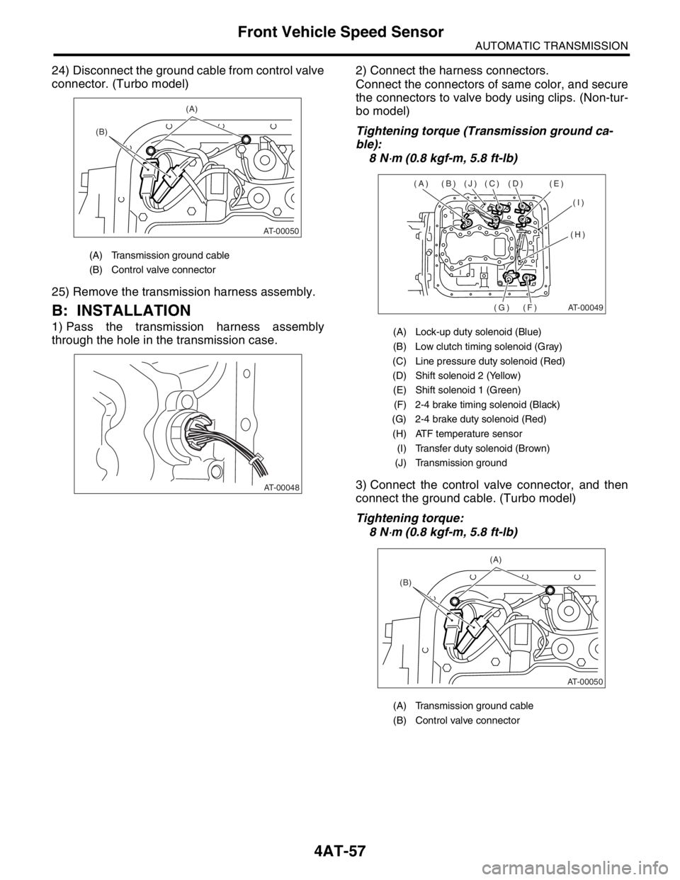
24) Disconnect the ground cable from control valve
connector. (Turbo model)
25) Remove the transmission harness assembly.
B: INSTALLATION
1) Pass the transmission harness assembly
through the hole in the transmission case.2) Connect the harness connectors.
Connect the connectors of same color, and secure
the connectors to valve body using clips. (Non-tur-
bo model)
Tightening torque (Transmission ground ca-
ble):
8 N
⋅m (0.8 kgf-m, 5.8 ft-lb)
3) Connect the control valve connector, and then
connect the ground cable. (Turbo model)
Tightening torque:
8 N
⋅m (0.8 kgf-m, 5.8 ft-lb)
(A) Transmission ground cable
(B) Control valve connector
AT-00050
(B)
(A)
AT-00048
(A) Lock-up duty solenoid (Blue)
(B) Low clutch timing solenoid (Gray)
(C) Line pressure duty solenoid (Red)
(D) Shift solenoid 2 (Yellow)
(E) Shift solenoid 1 (Green)
(F) 2-4 brake timing solenoid (Black)
(G) 2-4 brake duty solenoid (Red)
(H) ATF temperature sensor
(I) Transfer duty solenoid (Brown)
(J) Transmission ground
(A) Transmission ground cable
(B) Control valve connector
AT-00049
(A) (B) (J) (C) (D) (E)
(I)
(H)
(F) (G)
AT-00050
(B)
(A)