SUBARU FORESTER 2004 Service Repair Manual
Manufacturer: SUBARU, Model Year: 2004, Model line: FORESTER, Model: SUBARU FORESTER 2004Pages: 2870, PDF Size: 38.67 MB
Page 2381 of 2870
4AT-68
AUTOMATIC TRANSMISSION
Control Valve Body
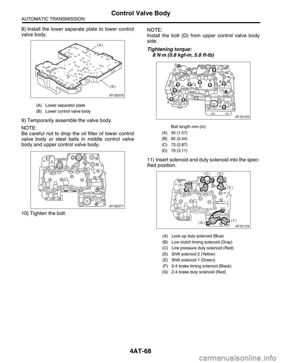
8) Install the lower separate plate to lower control
valve body.
9) Temporarily assemble the valve body.
NOTE:
Be careful not to drop the oil filter of lower control
valve body or steel balls in middle control valve
body and upper control valve body.
10) Tighten the bolt.NOTE:
Install the bolt (D) from upper control valve body
side.
Tightening torque:
8 N
⋅m (0.8 kgf-m, 5.8 ft-lb)
11) Insert solenoid and duty solenoid into the spec-
ified position.
(A) Lower separator plate
(B) Lower control valve body
AT-00076
(A)
(B)
AT-00077
Bolt length mm (in)
(A) 40 (1.57)
(B) 62 (2.44)
(C) 73 (2.87)
(D) 79 (3.11)
(A) Lock-up duty solenoid (Blue)
(B) Low clutch timing solenoid (Gray)
(C) Line pressure duty solenoid (Red)
(D) Shift solenoid 2 (Yellow)
(E) Shift solenoid 1 (Green)
(F) 2-4 brake timing solenoid (Black)
(G) 2-4 brake duty solenoid (Red)
AT-02125
B
B
BB D
C
B
D
AA
AA
AT-02124
(E)
(F)(G)
(D)(C)
(B)(A)
Page 2382 of 2870
4AT-69
AUTOMATIC TRANSMISSION
Control Valve Body
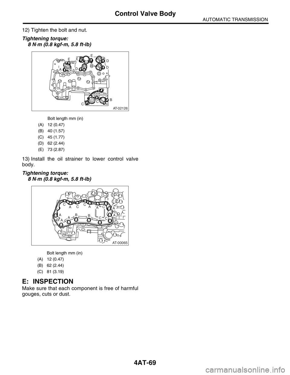
12) Tighten the bolt and nut.
Tightening torque:
8 N
⋅m (0.8 kgf-m, 5.8 ft-lb)
13) Install the oil strainer to lower control valve
body.
Tightening torque:
8 N
⋅m (0.8 kgf-m, 5.8 ft-lb)
E: INSPECTION
Make sure that each component is free of harmful
gouges, cuts or dust.
Bolt length mm (in)
(A) 12 (0.47)
(B) 40 (1.57)
(C) 45 (1.77)
(D) 62 (2.44)
(E) 73 (2.87)
Bolt length mm (in)
(A) 12 (0.47)
(B) 62 (2.44)
(C) 81 (3.19)
AT-02126
E
AD
EE
D
D
B
CC
AT-00065
A
ABAA
AC
ACC
AB
AC
CC
Page 2383 of 2870

4AT-70
AUTOMATIC TRANSMISSION
Air Bleeding of Control Valve
18.Air Bleeding of Control Valve
A: PROCEDURE
1) Lift-up the vehicle with shifting the select lever to
“P” range and applying the parking brake.
2) Connect the Subaru Select Monitor to the vehi-
cle.
3) Make sure there is no trouble code using Subaru
Select Monitor.
4) Using Subaru Select Monitor, check that the
ATF temperature is in less than 60°C (140°F).
5) Power OFF the Subaru Select Monitor.
6) Turn the ignition switch to “OFF”.
7) Shift the select lever to “R” range.
8) Depress the brake pedal fully until the air bleed-
ing is completed.
9) Turn the ignition switch to ON.
10) Shift the select lever to “P” range, and then wait
for more than 3 seconds.
11) Shift the select lever to “R” range, and then wait
for more than 3 seconds.
12) Shift the select lever to “N” range, and then wait
for more than 3 seconds.
13) Shift the select lever to “D” range, and then wait
for more than 3 seconds.
14) Shift the select lever to “N” range, and then wait
for more than 3 seconds.
15) Slightly depress the accelerator pedal fully.
16) Slightly release the accelerator pedal fully.
17) Start the engine.
18) Shift the select lever to “D” range.
19) Turn the Subaru Select Monitor switch to ON.
20) Select {Each System Check} in «Main Menu»
of Subaru Select Monitor.
21) On the «System Selection Menu» display
screen, select the “Transmission”. Air bleeding of
control valve starts on transmission. At this time,
the POWER indicator light in combination meter
blinks at 2 Hz. When the POWER indicator light
does not blink, repeat the procedures from step 4).
22) Air bleeding of control valve is finished when
blinking of POWER indicator light in combination
meter changes from 2 Hz to 0.5 Hz.
NOTE:
When blinking of POWER indicator light changes
from 2 Hz to 4 Hz during air bleeding, repeat the
procedure from step 4).
23) Shift the select lever to “N” range, and then turn
the ignition switch to OFF.
24) Shift the select lever to the “P” range, and then
finish the air bleeding.
Page 2384 of 2870
4AT-71
AUTOMATIC TRANSMISSION
Shift Solenoids, Duty Solenoids and ATF Temperature Sensor
19.Shift Solenoids, Duty Sole-
noids and ATF Temperature
Sensor
A: REMOVAL
1. SHIFT SOLENOID AND DUTY SOLE-
NOID
1) Lift-up the vehicle.
2) Clean the transmission exterior.
3) Drain the ATF completely.
4) Replace the gasket with new one, and then tight-
en the drain plug (ATF).
Tightening torque:
25 N
⋅m (2.5 kgf-m, 18.1 ft-lb)
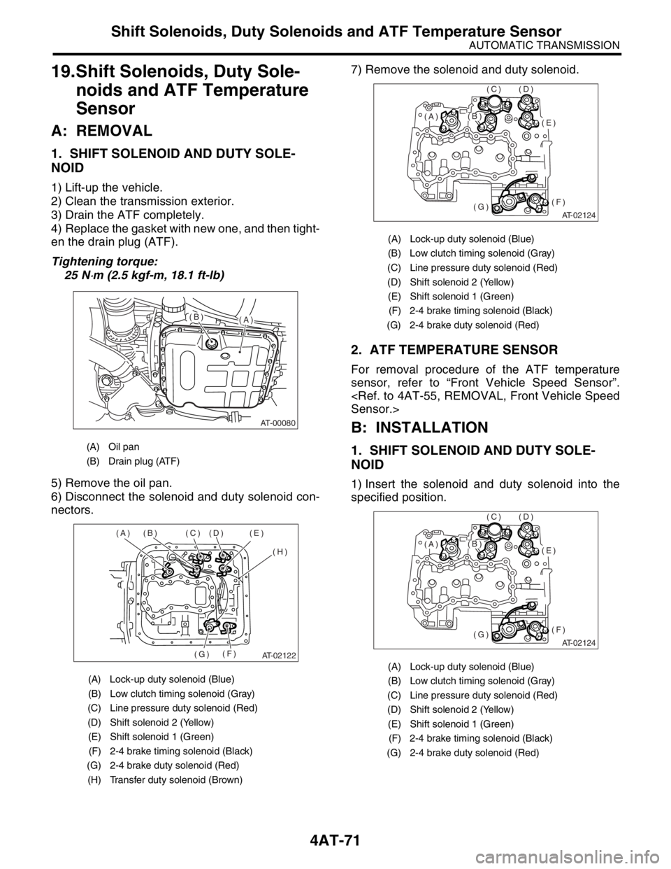
5) Remove the oil pan.
6) Disconnect the solenoid and duty solenoid con-
nectors.7) Remove the solenoid and duty solenoid.
2. ATF TEMPERATURE SENSOR
For removal procedure of the ATF temperature
sensor, refer to “Front Vehicle Speed Sensor”.
B: INSTALLATION
1. SHIFT SOLENOID AND DUTY SOLE-
NOID
1) Insert the solenoid and duty solenoid into the
specified position.
(A) Oil pan
(B) Drain plug (ATF)
(A) Lock-up duty solenoid (Blue)
(B) Low clutch timing solenoid (Gray)
(C) Line pressure duty solenoid (Red)
(D) Shift solenoid 2 (Yellow)
(E) Shift solenoid 1 (Green)
(F) 2-4 brake timing solenoid (Black)
(G) 2-4 brake duty solenoid (Red)
(H) Transfer duty solenoid (Brown)
AT-00080
(A)(B)
AT-02122
(A) (B) (C) (D) (E)
(H)
(F)
(G)
(A) Lock-up duty solenoid (Blue)
(B) Low clutch timing solenoid (Gray)
(C) Line pressure duty solenoid (Red)
(D) Shift solenoid 2 (Yellow)
(E) Shift solenoid 1 (Green)
(F) 2-4 brake timing solenoid (Black)
(G) 2-4 brake duty solenoid (Red)
(A) Lock-up duty solenoid (Blue)
(B) Low clutch timing solenoid (Gray)
(C) Line pressure duty solenoid (Red)
(D) Shift solenoid 2 (Yellow)
(E) Shift solenoid 1 (Green)
(F) 2-4 brake timing solenoid (Black)
(G) 2-4 brake duty solenoid (Red)
AT-02124
(E)
(F)(G)
(D)(C)
(B)(A)
AT-02124
(E)
(F)(G)
(D)(C)
(B)(A)
Page 2385 of 2870
4AT-72
AUTOMATIC TRANSMISSION
Shift Solenoids, Duty Solenoids and ATF Temperature Sensor
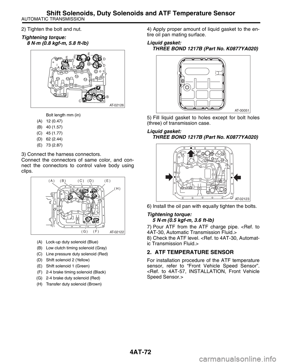
2) Tighten the bolt and nut.
Tightening torque:
8 N
⋅m (0.8 kgf-m, 5.8 ft-lb)
3) Connect the harness connectors.
Connect the connectors of same color, and con-
nect the connectors to control valve body using
clips.4) Apply proper amount of liquid gasket to the en-
tire oil pan mating surface.
Liquid gasket:
THREE BOND 1217B (Part No. K0877YA020)
5) Fill liquid gasket to holes except for bolt holes
(three) of transmission case.
Liquid gasket:
THREE BOND 1217B (Part No. K0877YA020)
6) Install the oil pan with equally tighten the bolts.
Tightening torque:
5 N
⋅m (0.5 kgf-m, 3.6 ft-lb)
7) Pour ATF from the ATF charge pipe.
8) Check the ATF level.
2. ATF TEMPERATURE SENSOR
For installation procedure of the ATF temperature
sensor, refer to “Front Vehicle Speed Sensor”.
Bolt length mm (in)
(A) 12 (0.47)
(B) 40 (1.57)
(C) 45 (1.77)
(D) 62 (2.44)
(E) 73 (2.87)
(A) Lock-up duty solenoid (Blue)
(B) Low clutch timing solenoid (Gray)
(C) Line pressure duty solenoid (Red)
(D) Shift solenoid 2 (Yellow)
(E) Shift solenoid 1 (Green)
(F) 2-4 brake timing solenoid (Black)
(G) 2-4 brake duty solenoid (Red)
(H) Transfer duty solenoid (Brown)
AT-02126
E
AD
EE
D
D
B
CC
AT-02122
(A) (B) (C) (D) (E)
(H)
(F)
(G)
AT-00051
AT-02123
Page 2386 of 2870
4AT-73
AUTOMATIC TRANSMISSION
Transfer Duty Solenoid and Valve Body
20.Transfer Duty Solenoid and
Valve Body
A: REMOVAL
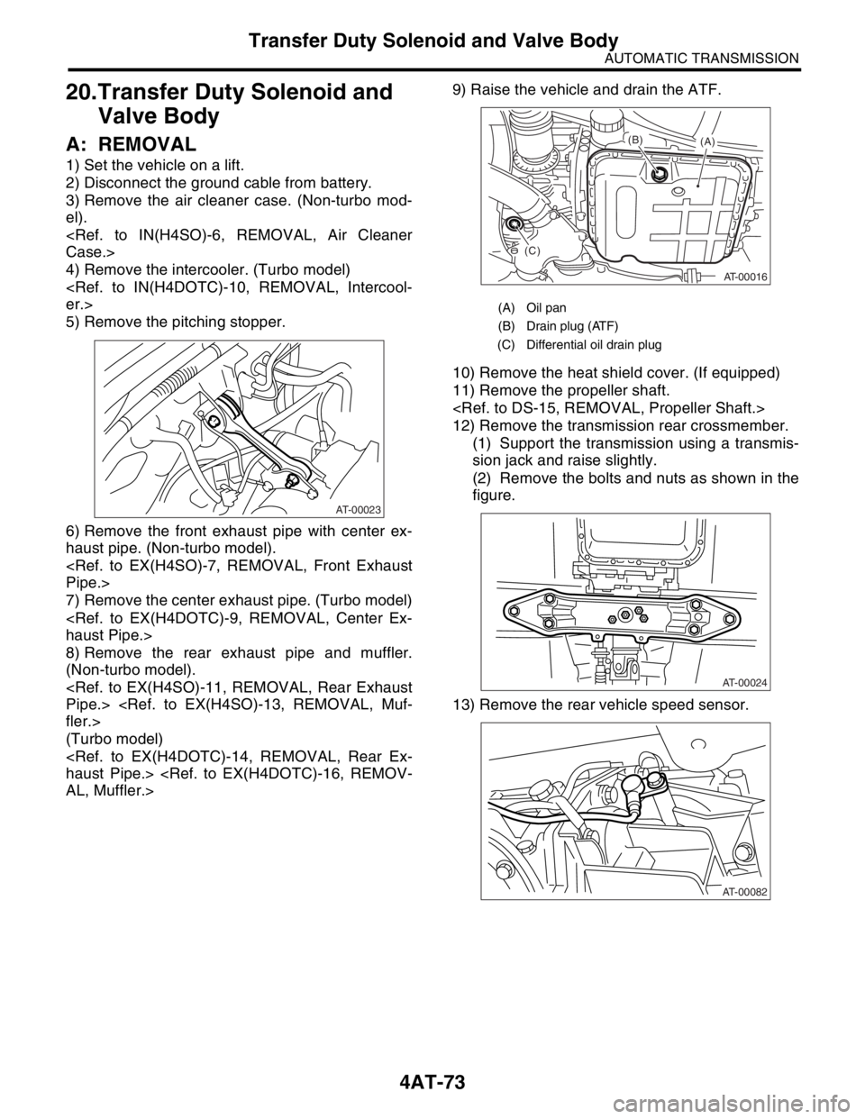
1) Set the vehicle on a lift.
2) Disconnect the ground cable from battery.
3) Remove the air cleaner case. (Non-turbo mod-
el).
4) Remove the intercooler. (Turbo model)
5) Remove the pitching stopper.
6) Remove the front exhaust pipe with center ex-
haust pipe. (Non-turbo model).
7) Remove the center exhaust pipe. (Turbo model)
8) Remove the rear exhaust pipe and muffler.
(Non-turbo model).
(Turbo model)
10) Remove the heat shield cover. (If equipped)
11) Remove the propeller shaft.
12) Remove the transmission rear crossmember.
(1) Support the transmission using a transmis-
sion jack and raise slightly.
(2) Remove the bolts and nuts as shown in the
figure.
13) Remove the rear vehicle speed sensor.
AT-00023
(A) Oil pan
(B) Drain plug (ATF)
(C) Differential oil drain plug
AT-00016
(A) (B)
(C)
AT-00024
AT-00082
Page 2387 of 2870
4AT-74
AUTOMATIC TRANSMISSION
Transfer Duty Solenoid and Valve Body
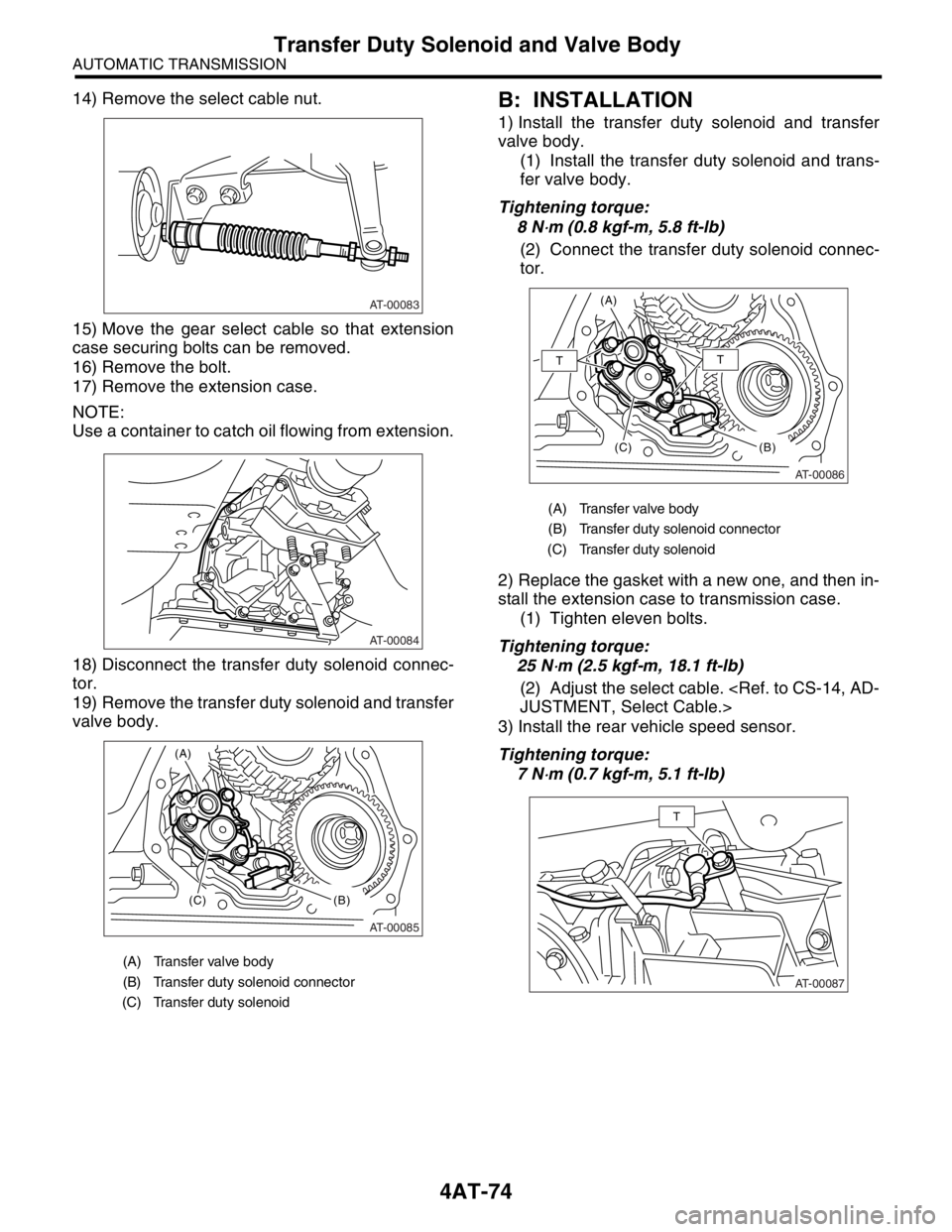
14) Remove the select cable nut.
15) Move the gear select cable so that extension
case securing bolts can be removed.
16) Remove the bolt.
17) Remove the extension case.
NOTE:
Use a container to catch oil flowing from extension.
18) Disconnect the transfer duty solenoid connec-
tor.
19) Remove the transfer duty solenoid and transfer
valve body.B: INSTALLATION
1) Install the transfer duty solenoid and transfer
valve body.
(1) Install the transfer duty solenoid and trans-
fer valve body.
Tightening torque:
8 N
⋅m (0.8 kgf-m, 5.8 ft-lb)
(2) Connect the transfer duty solenoid connec-
tor.
2) Replace the gasket with a new one, and then in-
stall the extension case to transmission case.
(1) Tighten eleven bolts.
Tightening torque:
25 N
⋅m (2.5 kgf-m, 18.1 ft-lb)
(2) Adjust the select cable.
3) Install the rear vehicle speed sensor.
Tightening torque:
7 N
⋅m (0.7 kgf-m, 5.1 ft-lb)
(A) Transfer valve body
(B) Transfer duty solenoid connector
(C) Transfer duty solenoid
AT-00083
AT-00084
AT-00085
(A)
(C)
(B)
(A) Transfer valve body
(B) Transfer duty solenoid connector
(C) Transfer duty solenoid
AT-00086
(A)
(C)
(B)
TT
AT-00087
T
Page 2388 of 2870
4AT-75
AUTOMATIC TRANSMISSION
Transfer Duty Solenoid and Valve Body
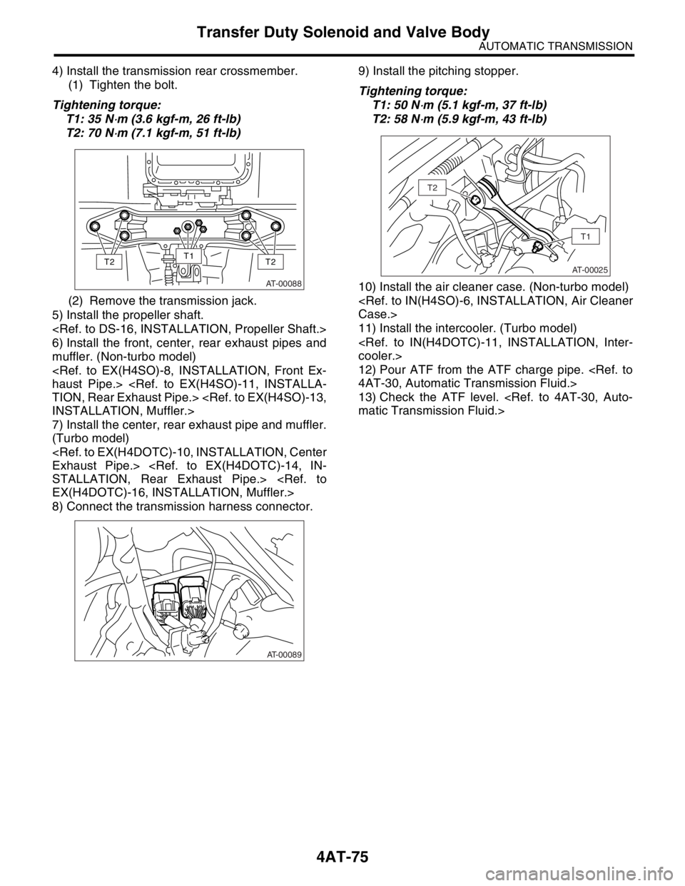
4) Install the transmission rear crossmember.
(1) Tighten the bolt.
Tightening torque:
T1: 35 N
⋅m (3.6 kgf-m, 26 ft-lb)
T2: 70 N
⋅m (7.1 kgf-m, 51 ft-lb)
(2) Remove the transmission jack.
5) Install the propeller shaft.
6) Install the front, center, rear exhaust pipes and
muffler. (Non-turbo model)
7) Install the center, rear exhaust pipe and muffler.
(Turbo model)
8) Connect the transmission harness connector.9) Install the pitching stopper.
Tightening torque:
T1: 50 N
⋅m (5.1 kgf-m, 37 ft-lb)
T2: 58 N
⋅m (5.9 kgf-m, 43 ft-lb)
10) Install the air cleaner case. (Non-turbo model)
11) Install the intercooler. (Turbo model)
12) Pour ATF from the ATF charge pipe.
13) Check the ATF level.
AT-00088
T2T2T1
AT-00089
AT-00025
T1
T2
Page 2389 of 2870
4AT-76
AUTOMATIC TRANSMISSION
ATF Filter
21.ATF Filter
A: REMOVAL
NOTE:
The ATF filter is maintenance free.
1) Lift-up the vehicle.
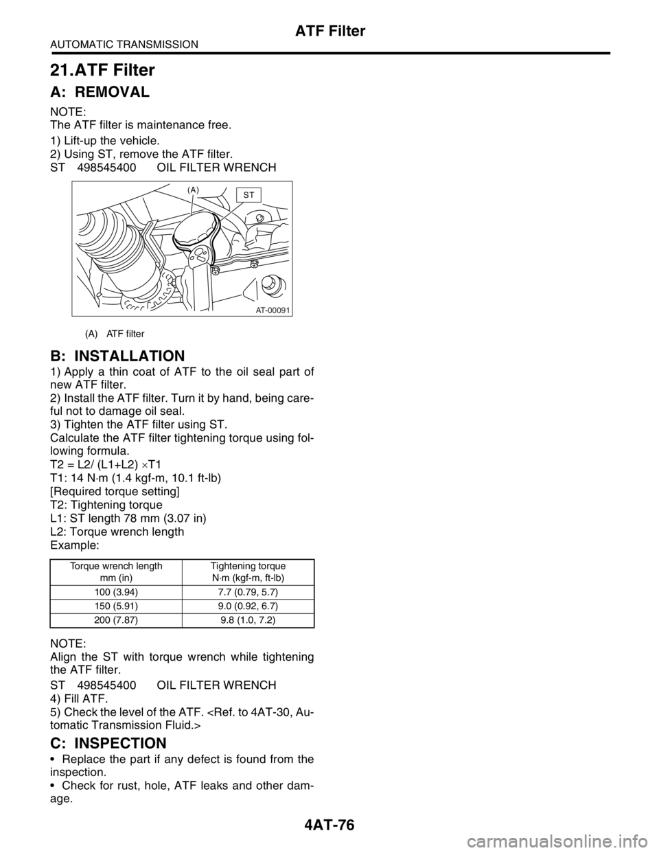
2) Using ST, remove the ATF filter.
ST 498545400 OIL FILTER WRENCH
B: INSTALLATION
1) Apply a thin coat of ATF to the oil seal part of
new ATF filter.
2) Install the ATF filter. Turn it by hand, being care-
ful not to damage oil seal.
3) Tighten the ATF filter using ST.
Calculate the ATF filter tightening torque using fol-
lowing formula.
T2 = L2/ (L1+L2) ×T1
T1: 14 N⋅m (1.4 kgf-m, 10.1 ft-lb)
[Required torque setting]
T2: Tightening torque
L1: ST length 78 mm (3.07 in)
L2: Torque wrench length
Example:
NOTE:
Align the ST with torque wrench while tightening
the ATF filter.
ST 498545400 OIL FILTER WRENCH
4) Fill ATF.
5) Check the level of the ATF.
C: INSPECTION
Replace the part if any defect is found from the
inspection.
Check for rust, hole, ATF leaks and other dam-
age.
(A) ATF filter
Torque wrench length
mm (in)Tightening torque
N⋅m (kgf-m, ft-lb)
100 (3.94) 7.7 (0.79, 5.7)
150 (5.91) 9.0 (0.92, 6.7)
200 (7.87) 9.8 (1.0, 7.2)
AT-00091
(A)ST
Page 2390 of 2870
4AT-77
AUTOMATIC TRANSMISSION
Transmission Control Module (TCM)
22.Transmission Control Mod-
ule (TCM)
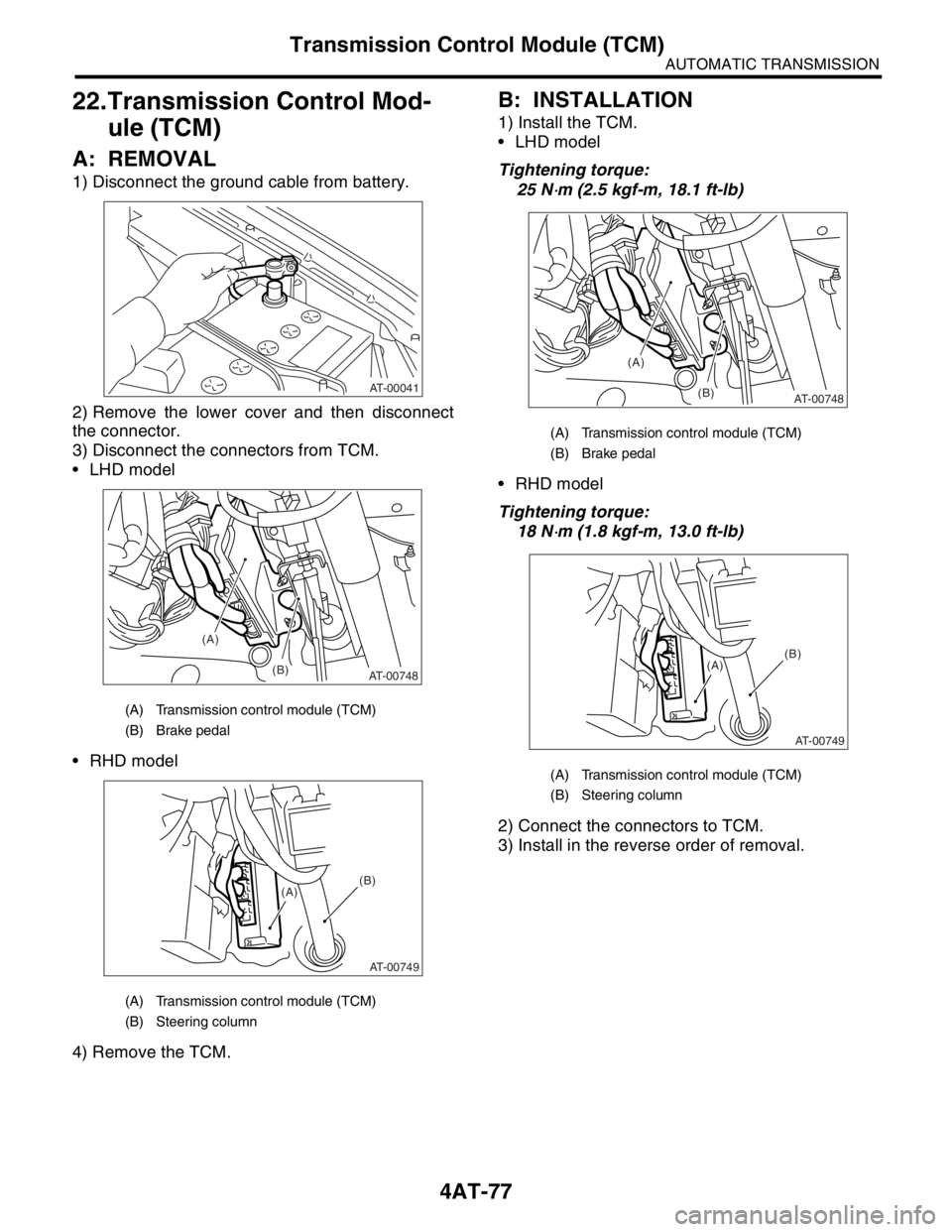
A: REMOVAL
1) Disconnect the ground cable from battery.
2) Remove the lower cover and then disconnect
the connector.
3) Disconnect the connectors from TCM.
LHD model
RHD model
4) Remove the TCM.
B: INSTALLATION
1) Install the TCM.
LHD model
Tightening torque:
25 N
⋅m (2.5 kgf-m, 18.1 ft-lb)
RHD model
Tightening torque:
18 N
⋅m (1.8 kgf-m, 13.0 ft-lb)
2) Connect the connectors to TCM.
3) Install in the reverse order of removal.
(A) Transmission control module (TCM)
(B) Brake pedal
(A) Transmission control module (TCM)
(B) Steering column
AT-00041
(A)
(B)
AT-00748
AT-00749
(A)(B)
(A) Transmission control module (TCM)
(B) Brake pedal
(A) Transmission control module (TCM)
(B) Steering column
(A)
(B)
AT-00748
AT-00749
(A)(B)