SUBARU FORESTER 2004 Service Repair Manual
Manufacturer: SUBARU, Model Year: 2004, Model line: FORESTER, Model: SUBARU FORESTER 2004Pages: 2870, PDF Size: 38.67 MB
Page 2481 of 2870

4AT(H4SO)-22
AUTOMATIC TRANSMISSION (DIAGNOSTIC)
Inspection Mode
8. Inspection Mode
A: OPERATION
Shift the select lever to “D” range, and drive continu-
ously for 10 seconds or more at 60 km/h (37 MPH).
WARNING:
Observe the road traffic law.
Page 2482 of 2870

4AT(H4SO)-23
AUTOMATIC TRANSMISSION (DIAGNOSTIC)
Clear Memory Mode
9. Clear Memory Mode
A: OPERATION
1. WITHOUT SUBARU SELECT MONITOR
Current DTC shown on display are cleared by turn-
ing the ignition switch to OFF after conducting on-
board diagnostics operation. Previous DTC, how-
ever, cannot be cleared since they are stored in the
TCM memory which is operating on back-up power
supply. These DTC can be cleared by removing the
specified TCM connector for at least two minutes.
CLEAR MEMORY:
Remove the TCM connector (B56) for at least
two minutes.
TCM connector (B56) is located in the line to
memory back-up power supply of TCM. Removal of
this connector clears the previous DTC stored in
TCM memory.
Be sure to remove TCM connector (B56) for at
least the specified length of time. Otherwise, the
DTC may not be cleared.
2. WITH SUBARU SELECT MONITOR
Refer to Subaru Select Monitor for information
about how to clear DTC.
Page 2483 of 2870

4AT(H4SO)-24
AUTOMATIC TRANSMISSION (DIAGNOSTIC)
Power Indicator Light Display
10.Power Indicator Light Display
A: OPERATION
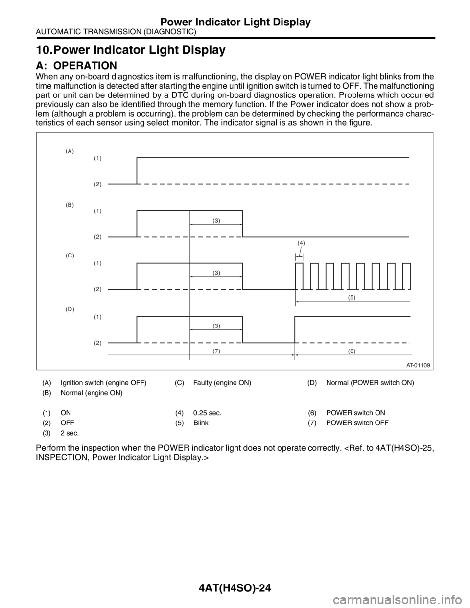
When any on-board diagnostics item is malfunctioning, the display on POWER indicator light blinks from the
time malfunction is detected after starting the engine until ignition switch is turned to OFF. The malfunctioning
part or unit can be determined by a DTC during on-board diagnostics operation. Problems which occurred
previously can also be identified through the memory function. If the Power indicator does not show a prob-
lem (although a problem is occurring), the problem can be determined by checking the performance charac-
teristics of each sensor using select monitor. The indicator signal is as shown in the figure.
Perform the inspection when the POWER indicator light does not operate correctly.
(A) Ignition switch (engine OFF) (C) Faulty (engine ON) (D) Normal (POWER switch ON)
(B) Normal (engine ON)
(1) ON (4) 0.25 sec. (6) POWER switch ON
(2) OFF (5) Blink (7) POWER switch OFF
(3) 2 sec.
AT-01109
(4)
(3)
(1)
(2)
(1)
(2)
(1)
(2)
(1)
(2)(3)
(3)(5)
(6) (A)
(B)
(C)
(D)
(7)
Page 2484 of 2870

4AT(H4SO)-25
AUTOMATIC TRANSMISSION (DIAGNOSTIC)
Power Indicator Light Display
B: INSPECTION
1. INSPECTION OF POWER INDICATOR LIGHT
DETECTING CONDITION:
The Power Indicator light circuit is open or shorted.
TROUBLE SYMPTOM:
When the ignition switch is turned to ON (engine OFF), POWER indicator light does not illuminate.
When the on-board diagnostics is performed, POWER indicator light remains illuminated.
Page 2485 of 2870

4AT(H4SO)-26
AUTOMATIC TRANSMISSION (DIAGNOSTIC)
Power Indicator Light Display
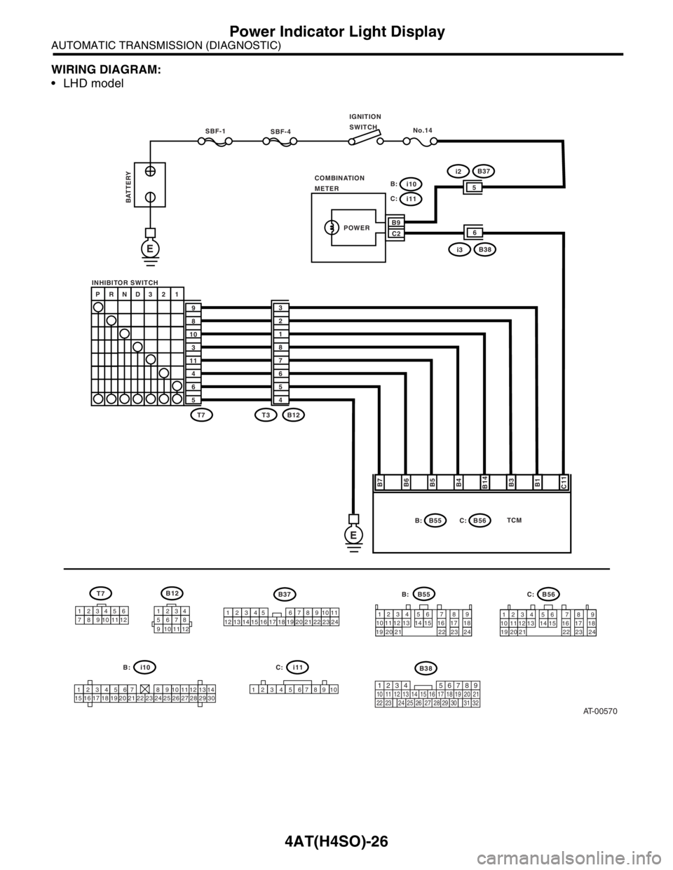
WIRING DIAGRAM:
LHD model
AT-00570
SBF-4No.14
COMBINATION
METERIGNITION
SWITCH
SBF-1
INHIBITOR SWITCH
E
E
BATTERY
B7
B6
B5
B4
B14
B3
B1
C11
P RND3 2 1
9
8
10
3
11
4
6
53
2
1
8
7
6
5
4
T7
T7B12
B55
B55 B37B56 T3 B12
1234
1234 56
12345656 12345
789
71234567891
0 897 7
8 8
9 9
10 11 12
10 11 10 11
12
13
10 11 12 1312 13
14
1415 14 15
16 16
17 18 17 18
19 20 21 19 20 21
22 23 24 22 23 241234 56 7 8 9
101112
13
1415
1516
1617
1718
1819
1920
2021
2122
2223
2324
24 25 26 27 28 29 30
B:
C:
B9
C2i2B37
POWER
B:
B56 C:TCM
i10 B:i11
1234
5678
9 101112
i10
i11
C:
i3B38
5
6
219
32
1234 5610 11 12 13 14 15716
23 3019 20
22 26 27 28 29817
24 3118
25
B38
6
C: B:
Page 2486 of 2870

4AT(H4SO)-27
AUTOMATIC TRANSMISSION (DIAGNOSTIC)
Power Indicator Light Display
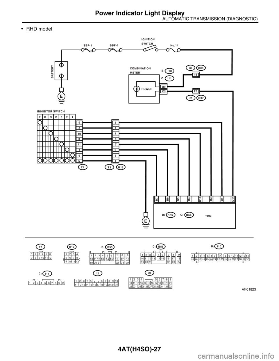
RHD model
AT-01823
SBF-4 No.14
COMBINATION
METER SBF-1
INHIBITOR SWITCH
E
E
B7
B6
B5
B4
B14
B3
B1
C11
P RND3 2 1
9
8
10
3
11
4
6
53
2
1
8
7
6
5
4
T7
T7B12
B55
B55
i2B56 T3 B12
12341234
5678
9
10
11
121234 56
123456 56
1234
5 7897
123456
7891089 7
68
79
8 10 1112
10 11
910 12
1310 1112
13
11
121414
15
131416
1517 18
16 192021
17 18192223 24
20 21221234
56789
101112
13
1415
15 16
16 17
17 18
18
1919
2020
2121
2222
2323
2424
2526
2728
29
30
i10
i11
B916
C2i3B38
POWER
B: C:B:
B56 C:
TCM
i10 B:
i11
IGNITION
SWITCH
BATTERY
12
i2B37
i3
219
32
1234 5610 11 12 13 14 15716
23 3019 20
22 26 27 28 29817
24 3118
25
C:
B:
C:
Page 2487 of 2870

4AT(H4SO)-28
AUTOMATIC TRANSMISSION (DIAGNOSTIC)
Power Indicator Light Display
Step Check Yes No
1 CHECK POWER INDICATOR LIGHT.
Turn the ignition switch to ON (engine OFF).Does the POWER indicator
light illuminate?Go to step 3.Go to step 2.
2 CHECK POWER INDICATOR LIGHT.
1) Turn the ignition switch to OFF.
2) Remove the combination meter.
3) Remove the POWER indicator light bulb
from combination meter.Is the POWER indicator light
bulb OK?Go to step 4.Replace the
POWER indicator
light bulb.
3 CHECK POWER INDICATOR LIGHT.
Perform “Read Diagnostic Trouble Code
(DTC)”.
light blink?A temporary poor
contact of the con-
nector or harness
may be the cause.
Repair the har-
ness or connector
in TCM, inhibitor
switch and combi-
nation meter.Go to step 9.
4 CHECK FUSE (No. 14).
Remove the fuse (No. 14).Is the fuse (No. 14) blown out? Replace the fuse
(No. 14). If
replaced fuse (No.
14) is blown out
easily, repair short
circuit in harness
between fuse (No.
14) and combina-
tion meter.Go to step 5.
5 CHECK HARNESS CONNECTOR BETWEEN
COMBINATION METER AND IGNITION
SWITCH.
1) Turn the ignition switch to ON (engine
OFF).
2) Measure the voltage between combination
meter connector and chassis ground.
Connector & terminal
(i10) No. 9 (+) — Chassis ground (
−):Is the voltage more than 9 V? Go to step 6.Repair the open
circuit in harness
between combina-
tion meter and bat-
tery.
6 CHECK COMBINATION METER.
Measure the voltage between combination
meter connector and chassis ground.
Connector & terminal
(i11) No. 2 (+) — Chassis ground (
−):Is the voltage less than 9 V? Repair the combi-
nation meter.
Meter Assembly.>Go to step 7.
7 CHECK OPEN CIRCUIT OF HARNESS.
1) Turn the ignition switch to OFF.
2) Disconnect the connector from combination
meter connector.
3) Measure the resistance of harness
between combination meter.
Connector & terminal
(B56) No. 11 — (i11) No. 2:Is the resistance less than 1
Ω?Go to step 8.Repair the open
circuit in harness
between TCM and
combination
meter, and poor
contact in cou-
pling connector.
8 CHECK INPUT SIGNAL FOR TCM.
1) Connect the connector to TCM and combi-
nation meter.
2) Turn the ignition switch to ON (engine
OFF).
3) Measure the voltage between TCM con-
nector and chassis ground.
Connector & terminal
(B56) No. 11 (+) — Chassis ground (
−):Is the voltage less than 1 V? Even if the
POWER indicator
lights up, the cir-
cuit has returned
to a normal condi-
tion at this time. A
temporary poor
contact of the con-
nector or harness
may be the cause.
Repair the har-
ness or connector
in TCM.Replace the TCM.
trol Module
(TCM).>
Page 2488 of 2870

4AT(H4SO)-29
AUTOMATIC TRANSMISSION (DIAGNOSTIC)
Power Indicator Light Display
9 CHECK INHIBITOR SWITCH.
1) Connect the Subaru Select Monitor to data
link connector.
2) Turn the ignition switch to ON.
3) Turn the Subaru Select Monitor to ON.
4) Read the data of range switch using Sub-
aru Select Monitor.
Range switch is indicated in ON ←→ OFF.When each range is selected,
does the LED of Subaru Select
Monitor light up?Go to step 10.Check the inhibi-
tor switch circuit.
CHECK INHIBI-
TOR SWITCH,
Diagnostic Proce-
dure without Diag-
nostic Trouble
Code (DTC).>
10 CHECK SHORT CIRCUIT OF HARNESS.
1) Disconnect the connector from TCM.
2) Remove the combination meter.
3) Disconnect the connector from combination
meter.
4) Measure the resistance of harness connec-
tor between TCM and chassis ground.
Connector & terminal
(B56) No. 11 — Chassis ground:Is the resistance less than 1
MΩ?Check the TCM
power supply and
ground line.
CHECK POWER
SUPPLY AND
GROUND LINE,
INSPECTION,
Power Indicator
Light Display.>Repair the short
circuit in harness
between combina-
tion meter connec-
tor and TCM
connector. Step Check Yes No
Page 2489 of 2870

4AT(H4SO)-30
AUTOMATIC TRANSMISSION (DIAGNOSTIC)
Power Indicator Light Display
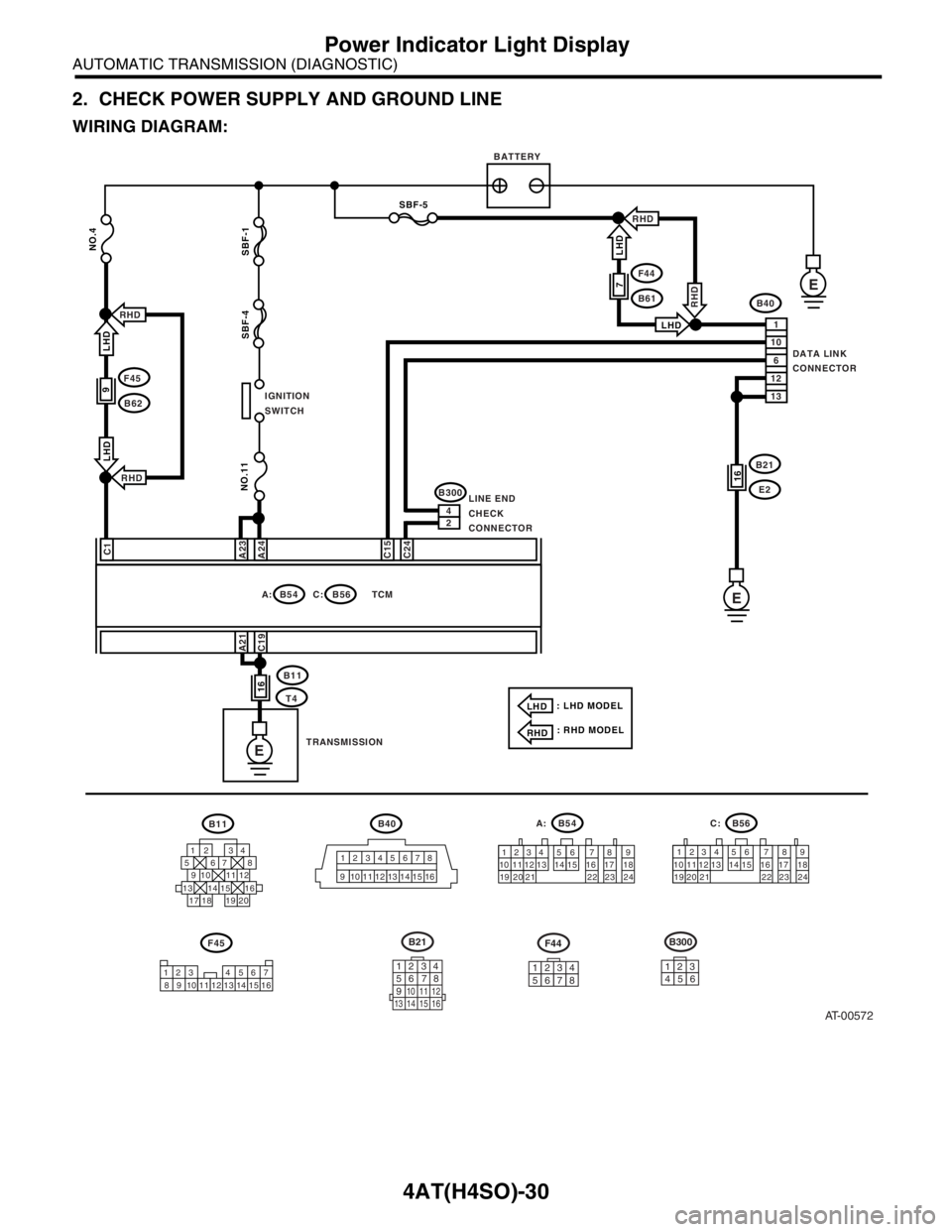
2. CHECK POWER SUPPLY AND GROUND LINE
WIRING DIAGRAM:
AT-00572
B40B11
F45
B54 A:B56
B11
T4
B40
DATA LINK
CONNECTOR
TCM C:
1 1
2 2
3 3
4 4
5
56
6778
8
9 9
13 14 15
20 19 171610 10
11 11
12
13 14 15 16 12
BATTERY
E
E
F45
B62
NO.4
NO.11
SBF-4 SBF-1 LHD
LHD
IGNITION
SWITCH
C1
A23
A24
C15
C24
18
123 4 567
8 9 10 12 13 14 15 1611
1234 5 6 7 8 9
10 11 12 13 14 15 16 17 18
19 20 21 22 23 241234 5 6 7 8 9
10 11 12 13 14 15 16 17 18
19 20 21 22 23 24
RHD
RHD
9
1
10
6
12
13
SBF-5
F44
B61
LHD
RHD
7
LHD
RHD
B21
E216
E
B21
1234
5678
9
10 11 12
13 14 15 16
12345678
F44
A21
C19
16
24
B300
LINE END
CHECK
CONNECTOR
: LHD MODEL
: RHD MODELLHD
RHD
123
456
B300
TRANSMISSION
B56C:B54A:
Page 2490 of 2870

4AT(H4SO)-31
AUTOMATIC TRANSMISSION (DIAGNOSTIC)
Power Indicator Light Display
Step Check Yes No
1 CHECK BATTERY TERMINAL.
Turn the ignition switch to OFF.Is there poor contact at battery
terminal?Repair or tighten
the battery termi-
nal.Go to step 2.
2 CHECK POWER SUPPLY OF TCM.
1) Disconnect the connector from TCM.
2) Turn the ignition switch to ON.
3) Measure the voltage between TCM con-
nector and chassis ground.
Connector & terminal
(B56) No. 1 (+) — Chassis ground (
−):Is the voltage 10 — 13 V? Go to step 4.Go to step 3.
3 CHECK FUSE (NO. 4).
Remove the fuse (No. 4).Is the fuse (No. 4) blown out? Replace the fuse
(No. 4). If replaced
fuse (No. 4) has
blown out easily,
repair short circuit
in harness
between fuse (No.
4) and TCM.Repair the open
circuit in harness
between fuse (No.
4) and TCM, or
fuse (No. 4) and
battery, and poor
contact in cou-
pling connector.
4 CHECK IGNITION POWER SUPPLY CIR-
CUIT.
1) Turn the ignition switch to ON (engine
OFF).
2) Measure the ignition power supply voltage
between TCM connector and chassis ground.
Connector & terminal
(B54) No. 23 (+) — Chassis ground (–):
(B54) No. 24 (+) — Chassis ground (–):Is the voltage 10 — 13 V? Go to step 6.Go to step 5.
5 CHECK FUSE (NO. 11).
Remove the fuse (No. 11).Is the fuse (No. 11) blown out? Replace the fuse
(No. 11). If
replaced fuse (No.
11) has blown out
easily, repair short
circuit in harness
between fuse (No.
11) and TCM.Repair the open
circuit in harness
between fuse (No.
11) and TCM, or
fuse (No. 11) and
battery, and poor
contact in cou-
pling connector.
6 CHECK HARNESS CONNECTOR BETWEEN
TCM AND TRANSMISSION.
1) Turn the ignition switch to OFF.
2) Disconnect the connector from TCM and
transmission.
3) Measure the resistance of harness
between TCM and transmission connector.
Connector & terminal
(B56) No. 19 — (B11) No. 16:
(B54) No. 21 — (B11) No. 16:Is the resistance less than 1
Ω?Go to step 7.Repair the open
circuit in harness
between TCM,
transmission har-
ness connector,
and poor contact
in coupling con-
nector.
7 CHECK HARNESS CONNECTOR BETWEEN
TRANSMISSION AND TRANSMISSION
GROUND.
Measure the resistance of harness between
transmission and transmission ground.
Connector & terminal
(T4) No. 16 — Transmission ground:Is the resistance less than 1
Ω?Go to step 8.Repair the open
circuit in harness
between transmis-
sion and transmis-
sion ground.
8 CHECK POOR CONTACT IN CONNECTORS.Is there poor contact in control
module power supply, ground
line and data link connector?Repair the con-
nector.Replace the TCM.
trol Module
(TCM).>