SUBARU FORESTER 2004 Service Repair Manual
Manufacturer: SUBARU, Model Year: 2004, Model line: FORESTER, Model: SUBARU FORESTER 2004Pages: 2870, PDF Size: 38.67 MB
Page 2441 of 2870
4AT-127
AUTOMATIC TRANSMISSION
AT Main Case
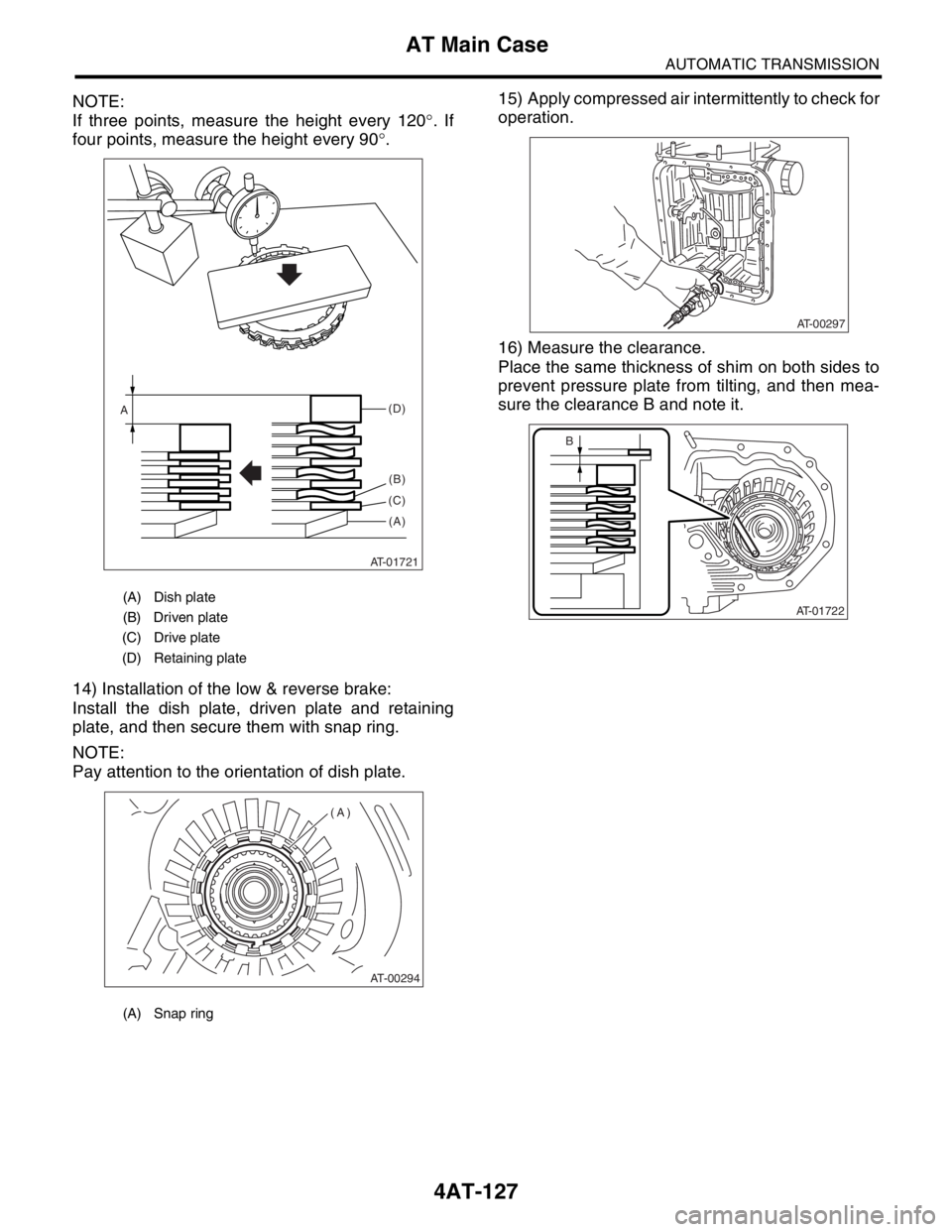
NOTE:
If three points, measure the height every 120°. If
four points, measure the height every 90°.
14) Installation of the low & reverse brake:
Install the dish plate, driven plate and retaining
plate, and then secure them with snap ring.
NOTE:
Pay attention to the orientation of dish plate.15) Apply compressed air intermittently to check for
operation.
16) Measure the clearance.
Place the same thickness of shim on both sides to
prevent pressure plate from tilting, and then mea-
sure the clearance B and note it.
(A) Dish plate
(B) Driven plate
(C) Drive plate
(D) Retaining plate
(A) Snap ring
AT-01721
(B)
(D)
(C)
(A)
A
AT-00294
(A)
AT-00297
AT-01722
B
Page 2442 of 2870
4AT-128
AUTOMATIC TRANSMISSION
AT Main Case
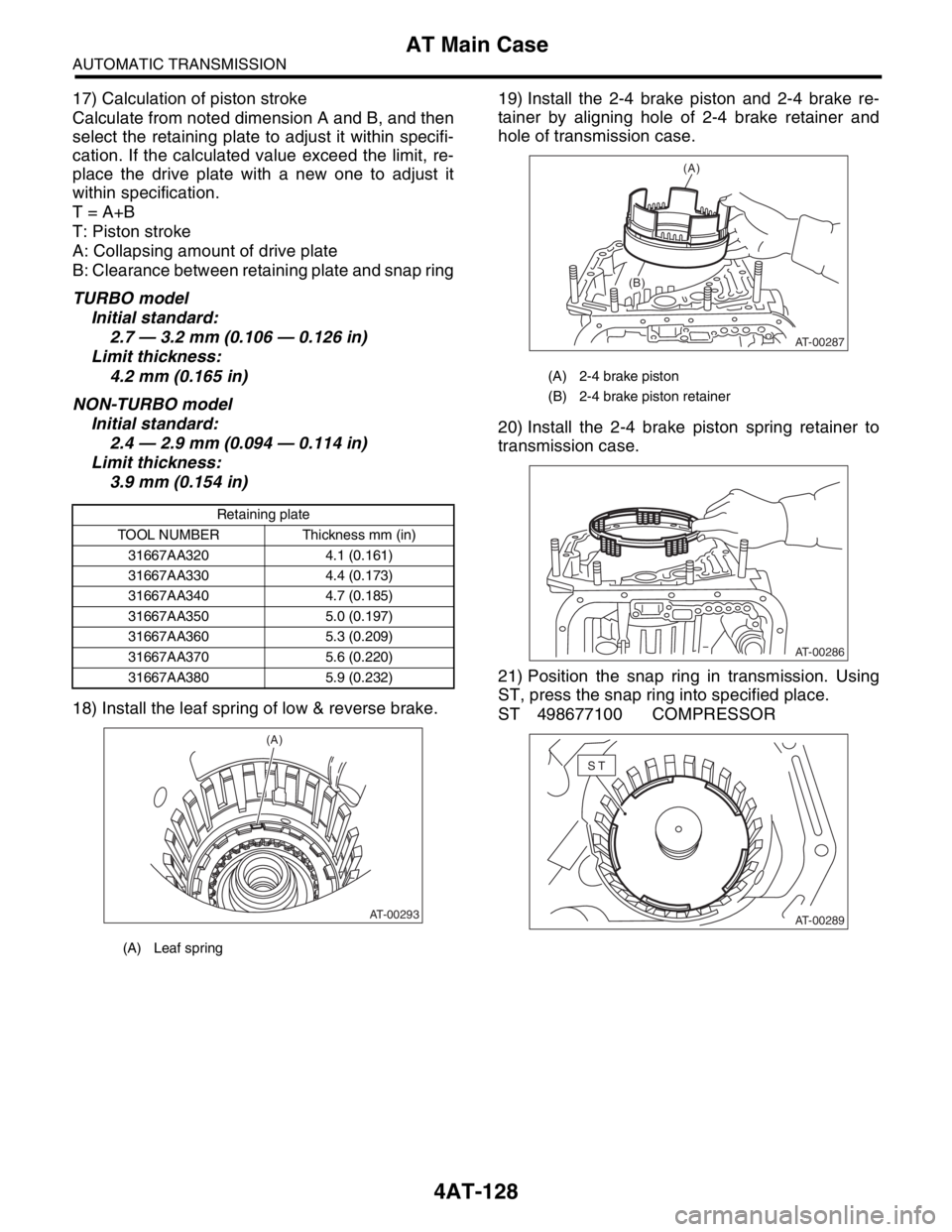
17) Calculation of piston stroke
Calculate from noted dimension A and B, and then
select the retaining plate to adjust it within specifi-
cation. If the calculated value exceed the limit, re-
place the drive plate with a new one to adjust it
within specification.
T = A+B
T: Piston stroke
A: Collapsing amount of drive plate
B: Clearance between retaining plate and snap ring
TURBO model
Initial standard:
2.7 — 3.2 mm (0.106 — 0.126 in)
Limit thickness:
4.2 mm (0.165 in)
NON-TURBO model
Initial standard:
2.4 — 2.9 mm (0.094 — 0.114 in)
Limit thickness:
3.9 mm (0.154 in)
18) Install the leaf spring of low & reverse brake.19) Install the 2-4 brake piston and 2-4 brake re-
tainer by aligning hole of 2-4 brake retainer and
hole of transmission case.
20) Install the 2-4 brake piston spring retainer to
transmission case.
21) Position the snap ring in transmission. Using
ST, press the snap ring into specified place.
ST 498677100 COMPRESSOR
Retaining plate
TOOL NUMBER Thickness mm (in)
31667AA320 4.1 (0.161)
31667AA330 4.4 (0.173)
31667AA340 4.7 (0.185)
31667AA350 5.0 (0.197)
31667AA360 5.3 (0.209)
31667AA370 5.6 (0.220)
31667AA380 5.9 (0.232)
(A) Leaf spring
AT-00293
(A)
(A) 2-4 brake piston
(B) 2-4 brake piston retainer
AT-00287
(A)
(B)
AT-00286
AT-00289
ST
Page 2443 of 2870
4AT-129
AUTOMATIC TRANSMISSION
AT Main Case
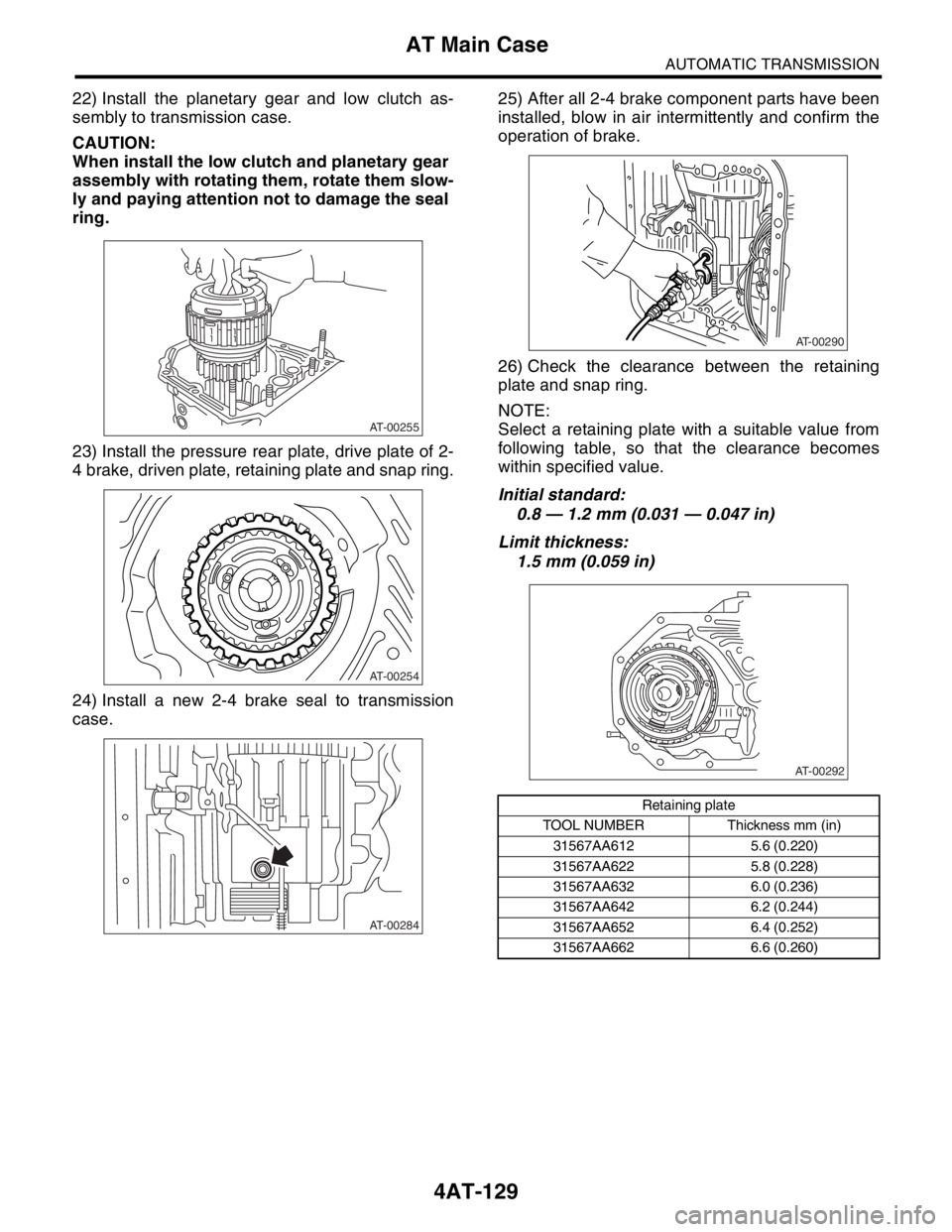
22) Install the planetary gear and low clutch as-
sembly to transmission case.
CAUTION:
When install the low clutch and planetary gear
assembly with rotating them, rotate them slow-
ly and paying attention not to damage the seal
ring.
23) Install the pressure rear plate, drive plate of 2-
4 brake, driven plate, retaining plate and snap ring.
24) Install a new 2-4 brake seal to transmission
case.25) After all 2-4 brake component parts have been
installed, blow in air intermittently and confirm the
operation of brake.
26) Check the clearance between the retaining
plate and snap ring.
NOTE:
Select a retaining plate with a suitable value from
following table, so that the clearance becomes
within specified value.
Initial standard:
0.8 — 1.2 mm (0.031 — 0.047 in)
Limit thickness:
1.5 mm (0.059 in)
AT-00255
AT-00254
AT-00284
Retaining plate
TOOL NUMBER Thickness mm (in)
31567AA612 5.6 (0.220)
31567AA622 5.8 (0.228)
31567AA632 6.0 (0.236)
31567AA642 6.2 (0.244)
31567AA652 6.4 (0.252)
31567AA662 6.6 (0.260)
AT-00290
AT-00292
Page 2444 of 2870
4AT-130
AUTOMATIC TRANSMISSION
AT Main Case
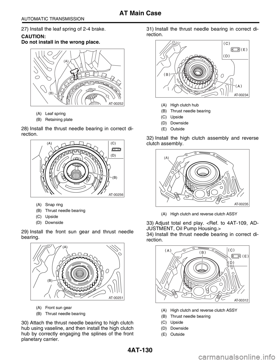
27) Install the leaf spring of 2-4 brake.
CAUTION:
Do not install in the wrong place.
28) Install the thrust needle bearing in correct di-
rection.
29) Install the front sun gear and thrust needle
bearing.
30) Attach the thrust needle bearing to high clutch
hub using vaseline, and then install the high clutch
hub by correctly engaging the splines of the front
planetary carrier.31) Install the thrust needle bearing in correct di-
rection.
32) Install the high clutch assembly and reverse
clutch assembly.
33) Adjust total end play.
34) Install the thrust needle bearing in correct di-
rection.
(A) Leaf spring
(B) Retaining plate
(A) Snap ring
(B) Thrust needle bearing
(C) Upside
(D) Downside
(A) Front sun gear
(B) Thrust needle bearing
AT-00252
(A)
(B)
AT-00256
(A)
(B) (C)
(D)
AT-00251
(A)
(B)
(A) High clutch hub
(B) Thrust needle bearing
(C) Upside
(D) Downside
(E) Outside
(A) High clutch and reverse clutch ASSY
(A) High clutch and reverse clutch ASSY
(B) Thrust needle bearing
(C) Upside
(D) Downside
(E) Outside
AT-00234
AT-00235
(A)
AT-00312
Page 2445 of 2870
4AT-131
AUTOMATIC TRANSMISSION
AT Main Case
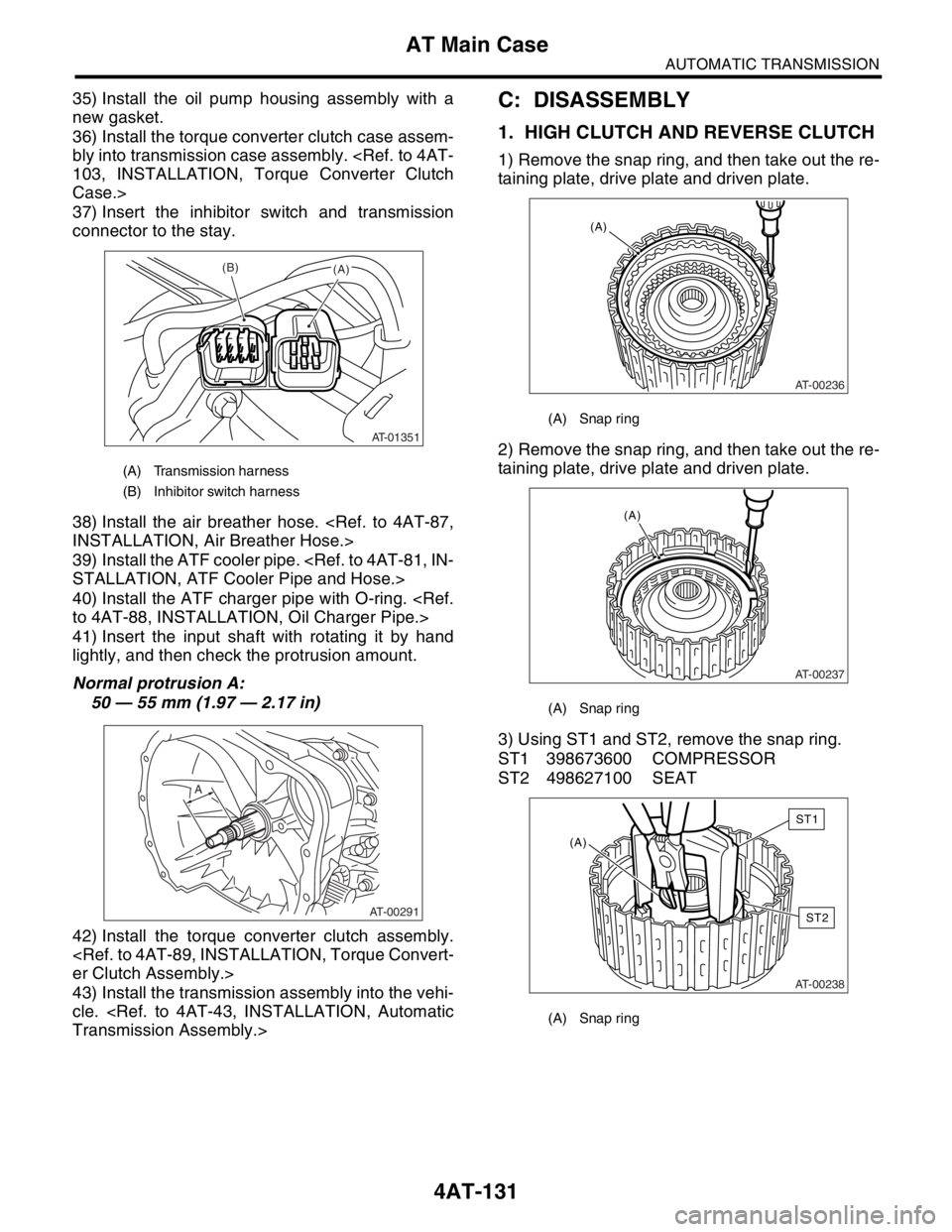
35) Install the oil pump housing assembly with a
new gasket.
36) Install the torque converter clutch case assem-
bly into transmission case assembly.
Case.>
37) Insert the inhibitor switch and transmission
connector to the stay.
38) Install the air breather hose.
39) Install the ATF cooler pipe.
40) Install the ATF charger pipe with O-ring.
41) Insert the input shaft with rotating it by hand
lightly, and then check the protrusion amount.
Normal protrusion A:
50 — 55 mm (1.97 — 2.17 in)
42) Install the torque converter clutch assembly.
43) Install the transmission assembly into the vehi-
cle.
1. HIGH CLUTCH AND REVERSE CLUTCH
1) Remove the snap ring, and then take out the re-
taining plate, drive plate and driven plate.
2) Remove the snap ring, and then take out the re-
taining plate, drive plate and driven plate.
3) Using ST1 and ST2, remove the snap ring.
ST1 398673600 COMPRESSOR
ST2 498627100 SEAT
(A) Transmission harness
(B) Inhibitor switch harness
AT-01351
(B)(A)
AT-00291
A
(A) Snap ring
(A) Snap ring
(A) Snap ring
AT-00236
(A)
AT-00237
(A)
AT-00238
(A)
ST1
ST2
Page 2446 of 2870
4AT-132
AUTOMATIC TRANSMISSION
AT Main Case
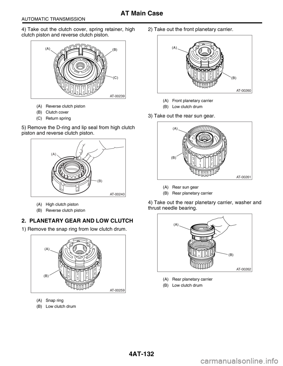
4) Take out the clutch cover, spring retainer, high
clutch piston and reverse clutch piston.
5) Remove the D-ring and lip seal from high clutch
piston and reverse clutch piston.
2. PLANETARY GEAR AND LOW CLUTCH
1) Remove the snap ring from low clutch drum.2) Take out the front planetary carrier.
3) Take out the rear sun gear.
4) Take out the rear planetary carrier, washer and
thrust needle bearing.
(A) Reverse clutch piston
(B) Clutch cover
(C) Return spring
(A) High clutch piston
(B) Reverse clutch piston
(A) Snap ring
(B) Low clutch drum
AT-00239
(A)(B)
(C)
AT-00240
(A)
(B)
AT-00259
(A)
(B)
(A) Front planetary carrier
(B) Low clutch drum
(A) Rear sun gear
(B) Rear planetary carrier
(A) Rear planetary carrier
(B) Low clutch drum
AT-00260
(B) (A)
AT-00261
(B)(A)
AT-00262
(B)
(A)
Page 2447 of 2870
4AT-133
AUTOMATIC TRANSMISSION
AT Main Case
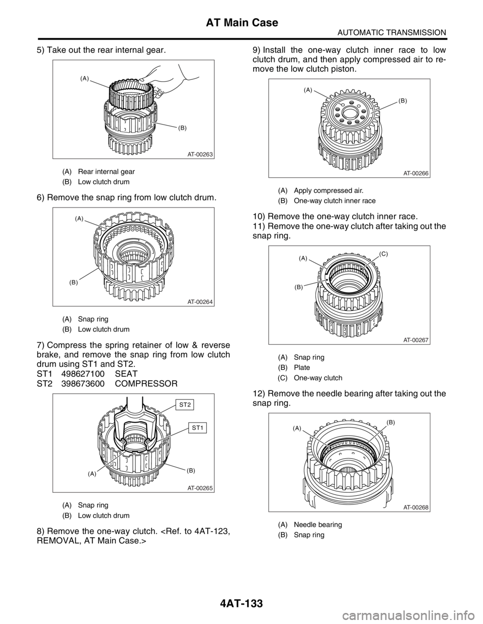
5) Take out the rear internal gear.
6) Remove the snap ring from low clutch drum.
7) Compress the spring retainer of low & reverse
brake, and remove the snap ring from low clutch
drum using ST1 and ST2.
ST1 498627100 SEAT
ST2 398673600 COMPRESSOR
8) Remove the one-way clutch.
clutch drum, and then apply compressed air to re-
move the low clutch piston.
10) Remove the one-way clutch inner race.
11) Remove the one-way clutch after taking out the
snap ring.
12) Remove the needle bearing after taking out the
snap ring.
(A) Rear internal gear
(B) Low clutch drum
(A) Snap ring
(B) Low clutch drum
(A) Snap ring
(B) Low clutch drum
AT-00263
(B)
(A)
AT-00264
(B)
(A)
AT-00265
(B)(A)
ST1
ST2
(A) Apply compressed air.
(B) One-way clutch inner race
(A) Snap ring
(B) Plate
(C) One-way clutch
(A) Needle bearing
(B) Snap ring
AT-00266
(B) (A)
AT-00267
(A)(C)
(B)
AT-00268
(B)(A)
Page 2448 of 2870
4AT-134
AUTOMATIC TRANSMISSION
AT Main Case
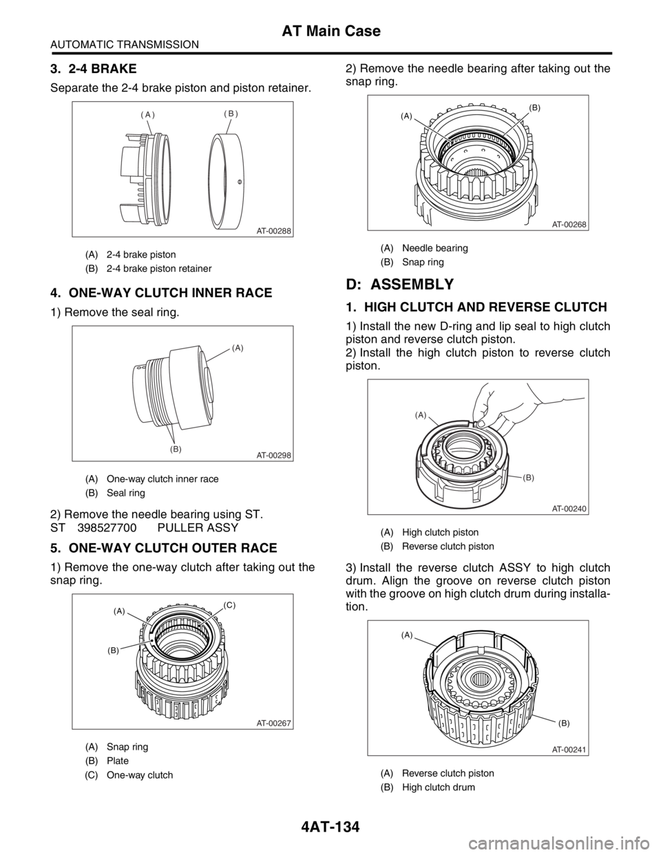
3. 2-4 BRAKE
Separate the 2-4 brake piston and piston retainer.
4. ONE-WAY CLUTCH INNER RACE
1) Remove the seal ring.
2) Remove the needle bearing using ST.
ST 398527700 PULLER ASSY
5. ONE-WAY CLUTCH OUTER RACE
1) Remove the one-way clutch after taking out the
snap ring.2) Remove the needle bearing after taking out the
snap ring.
D: ASSEMBLY
1. HIGH CLUTCH AND REVERSE CLUTCH
1) Install the new D-ring and lip seal to high clutch
piston and reverse clutch piston.
2) Install the high clutch piston to reverse clutch
piston.
3) Install the reverse clutch ASSY to high clutch
drum. Align the groove on reverse clutch piston
with the groove on high clutch drum during installa-
tion.
(A) 2-4 brake piston
(B) 2-4 brake piston retainer
(A) One-way clutch inner race
(B) Seal ring
(A) Snap ring
(B) Plate
(C) One-way clutch
AT-00288
(A)(B)
AT-00298(B)(A)
AT-00267
(A)(C)
(B)
(A) Needle bearing
(B) Snap ring
(A) High clutch piston
(B) Reverse clutch piston
(A) Reverse clutch piston
(B) High clutch drum
AT-00268
(B)(A)
AT-00240
(A)
(B)
AT-00241
(A)
(B)
Page 2449 of 2870
4AT-135
AUTOMATIC TRANSMISSION
AT Main Case
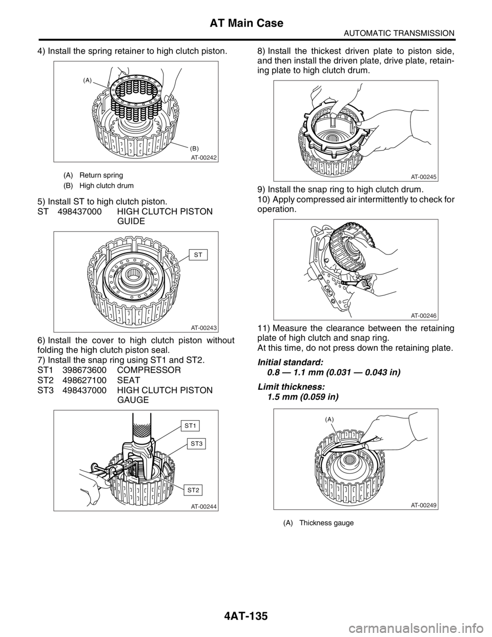
4) Install the spring retainer to high clutch piston.
5) Install ST to high clutch piston.
ST 498437000 HIGH CLUTCH PISTON
GUIDE
6) Install the cover to high clutch piston without
folding the high clutch piston seal.
7) Install the snap ring using ST1 and ST2.
ST1 398673600 COMPRESSOR
ST2 498627100 SEAT
ST3 498437000 HIGH CLUTCH PISTON
GAUGE8) Install the thickest driven plate to piston side,
and then install the driven plate, drive plate, retain-
ing plate to high clutch drum.
9) Install the snap ring to high clutch drum.
10) Apply compressed air intermittently to check for
operation.
11) Measure the clearance between the retaining
plate of high clutch and snap ring.
At this time, do not press down the retaining plate.
Initial standard:
0.8 — 1.1 mm (0.031 — 0.043 in)
Limit thickness:
1.5 mm (0.059 in)
(A) Return spring
(B) High clutch drum
AT-00242
(B)
(A)
AT-00243
ST
AT-00244
ST1
ST3
ST2
(A) Thickness gauge
AT-00245
AT-00246
AT-00249
(A)
Page 2450 of 2870
4AT-136
AUTOMATIC TRANSMISSION
AT Main Case
If the specified tolerance limits are exceeded, se-
lect a suitable retaining plate.
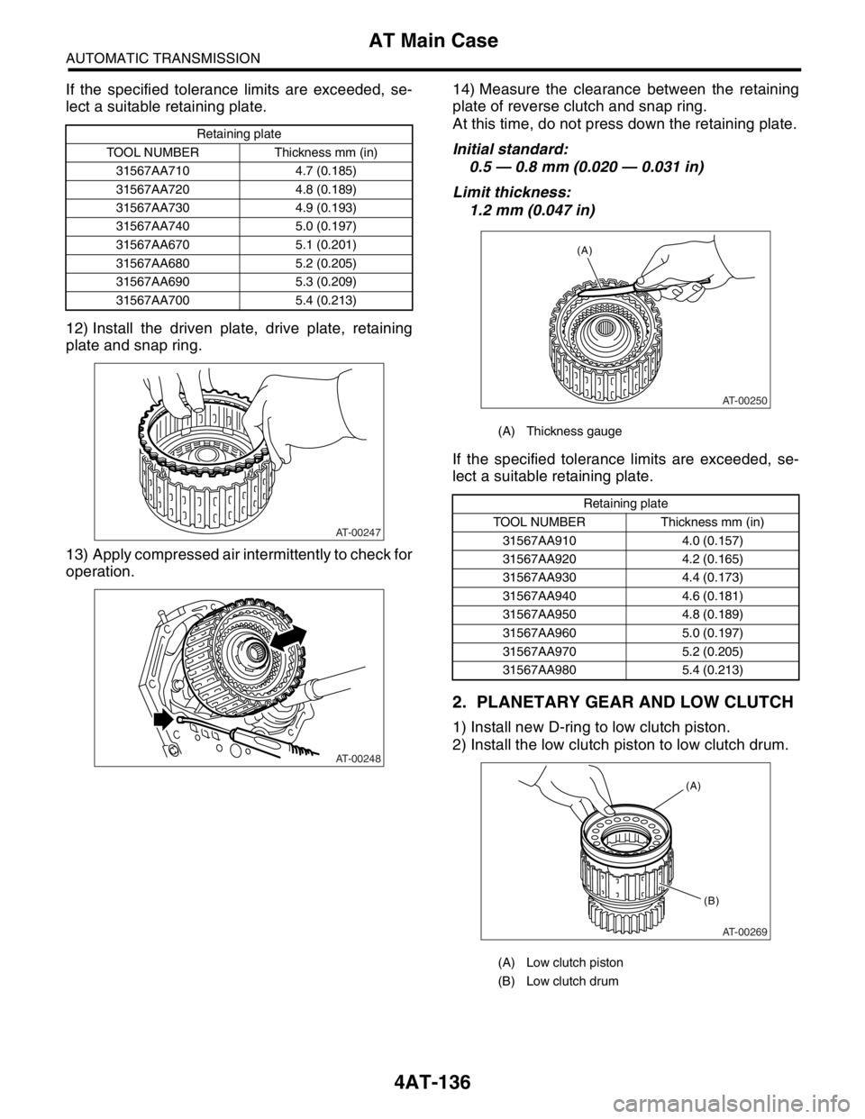
12) Install the driven plate, drive plate, retaining
plate and snap ring.
13) Apply compressed air intermittently to check for
operation.14) Measure the clearance between the retaining
plate of reverse clutch and snap ring.
At this time, do not press down the retaining plate.
Initial standard:
0.5 — 0.8 mm (0.020 — 0.031 in)
Limit thickness:
1.2 mm (0.047 in)
If the specified tolerance limits are exceeded, se-
lect a suitable retaining plate.
2. PLANETARY GEAR AND LOW CLUTCH
1) Install new D-ring to low clutch piston.
2) Install the low clutch piston to low clutch drum.
Retaining plate
TOOL NUMBER Thickness mm (in)
31567AA710 4.7 (0.185)
31567AA720 4.8 (0.189)
31567AA730 4.9 (0.193)
31567AA740 5.0 (0.197)
31567AA670 5.1 (0.201)
31567AA680 5.2 (0.205)
31567AA690 5.3 (0.209)
31567AA700 5.4 (0.213)
AT-00247
AT-00248
(A) Thickness gauge
Retaining plate
TOOL NUMBER Thickness mm (in)
31567AA910 4.0 (0.157)
31567AA920 4.2 (0.165)
31567AA930 4.4 (0.173)
31567AA940 4.6 (0.181)
31567AA950 4.8 (0.189)
31567AA960 5.0 (0.197)
31567AA970 5.2 (0.205)
31567AA980 5.4 (0.213)
(A) Low clutch piston
(B) Low clutch drum
AT-00250
(A)
AT-00269
(B) (A)