oil temperature SUBARU FORESTER 2004 Service Owner's Manual
[x] Cancel search | Manufacturer: SUBARU, Model Year: 2004, Model line: FORESTER, Model: SUBARU FORESTER 2004Pages: 2870, PDF Size: 38.67 MB
Page 1354 of 2870

EN(H4SO)-256
ENGINE (DIAGNOSTIC)
General Diagnostic Table
*1: Check ignition coil & ignitor ASSY and spark plug.
*2: Indicate the symptom occurring only in cold temperatures.
*3: Ensure the secure installation.
*4: Check fuel injector, fuel pressure regulator and fuel filter.
*5: Inspect air leak in air intake system.
*6: Adjust the accelerator cable.
2. AUTOMATIC TRANSMISSION
NOTE:
Check general diagnostics table with non-conformity symptom for automatic transmission.
6. Surging1) Intake manifold pressure sensor
2) Intake air temperature sensor
3) Manifold absolute pressure sensor
4) Engine coolant temperature sensor (*2)
5) Crankshaft position sensor (*3)
6) Camshaft position sensor (*3)
7) Fuel injection parts (*4)
8) Throttle position sensor
9) Fuel pump and fuel pump relay
7. Spark knock1) Intake manifold pressure sensor
2) Intake air temperature sensor
3) Manifold absolute pressure sensor
4) Engine coolant temperature sensor
5) Knock sensor
6) Fuel injection parts (*4)
7) Fuel pump and fuel pump relay
8. After burning in exhaust system1) Intake manifold pressure sensor
2) Intake air temperature sensor
3) Manifold absolute pressure sensor
4) Engine coolant temperature sensor (*2)
5) Fuel injection parts (*4)
6) Fuel pump and fuel pump relay Symptom Problem parts
Page 1370 of 2870
FU(H4DOTC)-15
FUEL INJECTION (FUEL SYSTEM)
Intake Manifold
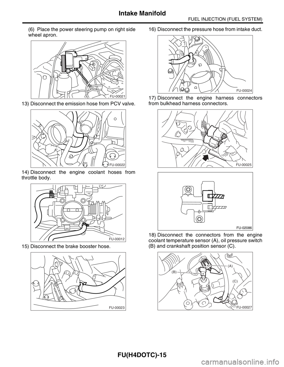
(6) Place the power steering pump on right side
wheel apron.
13) Disconnect the emission hose from PCV valve.
14) Disconnect the engine coolant hoses from
throttle body.
15) Disconnect the brake booster hose.16) Disconnect the pressure hose from intake duct.
17) Disconnect the engine harness connectors
from bulkhead harness connectors.
18) Disconnect the connectors from the engine
coolant temperature sensor (A), oil pressure switch
(B) and crankshaft position sensor (C).
FU-00021
FU-00022
FU-00012
FU-00023
FU-00024
FU-00025
FU-02086
(A)
(B)
(C)
FU-00027
Page 1373 of 2870
FU(H4DOTC)-18
FUEL INJECTION (FUEL SYSTEM)
Intake Manifold
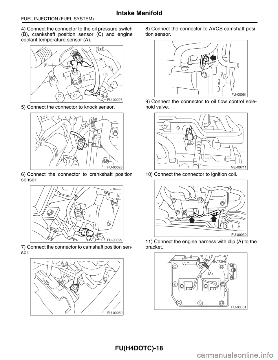
4) Connect the connector to the oil pressure switch
(B), crankshaft position sensor (C) and engine
coolant temperature sensor (A).
5) Connect the connector to knock sensor.
6) Connect the connector to crankshaft position
sensor.
7) Connect the connector to camshaft position sen-
sor.8) Connect the connector to AVCS camshaft posi-
tion sensor.
9) Connect the connector to oil flow control sole-
noid valve.
10) Connect the connector to ignition coil.
11) Connect the engine harness with clip (A) to the
bracket.
(A)
(B)
(C)
FU-00027
FU-00028
FU-00029
FU-00059
FU-00061
ME-00711
FU-00030
FU-00031
(A)
Page 1664 of 2870
![SUBARU FORESTER 2004 Service Owners Manual EN(H4DOTC)-34
ENGINE (DIAGNOSTIC)
Subaru Select Monitor
4. READ CURRENT DATA FOR ENGINE. (NORMAL MODE)
1) On the «Main Menu» display screen, select the {Each System Check} and press the [YES] key.
2](/img/17/57426/w960_57426-1663.png "SUBARU FORESTER 2004 Service Owners Manual EN(H4DOTC)-34
ENGINE (DIAGNOSTIC)
Subaru Select Monitor
4. READ CURRENT DATA FOR ENGINE. (NORMAL MODE)
1) On the «Main Menu» display screen, select the {Each System Check} and press the [YES] key.
2")
EN(H4DOTC)-34
ENGINE (DIAGNOSTIC)
Subaru Select Monitor
4. READ CURRENT DATA FOR ENGINE. (NORMAL MODE)
1) On the «Main Menu» display screen, select the {Each System Check} and press the [YES] key.
2) On the «System Selection Menu» display screen, select the {Engine} and press the [YES] key.
3) Press the [YES] key after the information of engine type was displayed.
4) On the «Engine Diagnosis» screen, select the {Current Data Display/Save}, and then press the [YES] key.
5) On the «Data Display Menu» screen, select the {Data Display} and press the [YES] key.
6) Using the scroll key, move the display screen up or down until the desired data is shown.
A list of the support data is shown in the following table.
Remarks Display Unit of measure
Battery voltage Battery Voltage V
Vehicle speed signal Vehicle Speed km/h or MPH
Engine speed signal Engine Speed rpm
Engine coolant temperature signal Coolant Temp.°C or °F
Ignition timing signal Ignition Timing deg
Throttle position signal Throttle Opening Angle %
Throttle position signal Throttle Sensor Voltage V
Injection pulse width Fuel Injection #1 Pulse ms
Idle air control signal ISC Valve Duty Ratio %
generated duty control signal ALT Duty %
Fuel pump duty control signal Fuel Pump Duty %
A/F sensor current A/F Sensor #1 Current mA
A/F sensor resistance A/F Sensor #1 ResistanceΩ
Front oxygen (A/F) sensor output signal A/F Sensor #1 —
Rear oxygen sensor output signalRear O
2 Sensor
V
Short term fuel trim A/F Correction #1 %
Knock sensor correction Knocking Correction deg
Atmospheric pressure signal Atmosphere Pressure mmHg, kPa, inHg or psi
Intake manifold relative pressure signal Mani. Relative Pressure mmHg, kPa, inHg or psi
Intake manifold absolute pressure signal Mani. Absolute Pressure mmHg, kPa, inHg or psi
A/F correction (short term fuel trim) by rear oxygen sensor A/F Correction #3 %
Long term whole fuel trim A/F Learning #1 %
Canister purge control solenoid valve duty ratio CPC Valve Duty Ratio %
Primary supercharged pressure control signal Primary Control %
Tumble generated valve position sensor signal (RH side) TGV Position Sensor R V
Tumble generated valve position sensor signal (LH side) TGV Position Sensor L V
Tumble generated valve drive signal TGV Drive OPEN or CLOSE
Fuel level signal Fuel Level Voltage V
Intake air temperature signal Intake Air Temp.°C or °F
Mass air flow sensor signal Mass Air Flow g/s
Mass air flow sensor signal Air Flow Sensor Voltage V
Valve Timing Signal VVT Adv. Ang. amount R deg
Valve Timing Signal VVT Adv. Ang. amount L deg
Oil flow control solenoid valve signal OCV Duty R %
Oil flow control solenoid valve signal OCV Duty L %
Oil flow control solenoid valve current OCV current R mA
Oil flow control solenoid valve current OCV Current L mA
AT/MT identification signal AT Vehicle ID Signal AT or MT
Test Mode Signal Test Mode Signal ON or OFF
Load switch signal Electric Load Signal ON or OFF
Ignition switch signal Ignition Switch ON or OFF
Neutral position switch signal Neutral Position Switch ON or OFF
Air conditioning switch signal A/C Switch ON or OFF
Page 1929 of 2870

EN(H4DOTC)-296
ENGINE (DIAGNOSTIC)
General Diagnostic Table
*1: Check ignition coil & ignitor ASSY and spark plug.
*2: Indicate the symptom occurring only in cold temperatures.
*3: Ensure the secure installation.
*4: Check fuel injector, fuel pressure regulator and fuel filter.
*5: Inspect air leak in air intake system.
*6: Adjust accelerator cable. 6. Surging1) Manifold absolute pressure sensor
2) Mass air flow and intake air temperature sensor
3) Engine coolant temperature sensor (*2)
4) Crankshaft position sensor (*3)
5) Camshaft position sensor (*3)
6) Fuel injection parts (*4)
7) Throttle position sensor
8) Fuel pump and fuel pump relay
7. Spark knock1) Manifold absolute pressure sensor
2) Mass air flow and intake air temperature sensor
3) Engine coolant temperature sensor
4) Knock sensor
5) Fuel injection parts (*4)
6) Fuel pump and fuel pump relay
8. After burning in exhaust system1) Manifold absolute pressure sensor
2) Mass air flow and intake air temperature sensor
3) Engine coolant temperature sensor (*2)
4) Fuel injection parts (*4)
5) Fuel pump and fuel pump relay Symptom Problem parts
Page 1945 of 2870
FU(H4DOTC 2.5)-15
FUEL INJECTION (FUEL SYSTEM)
Intake Manifold
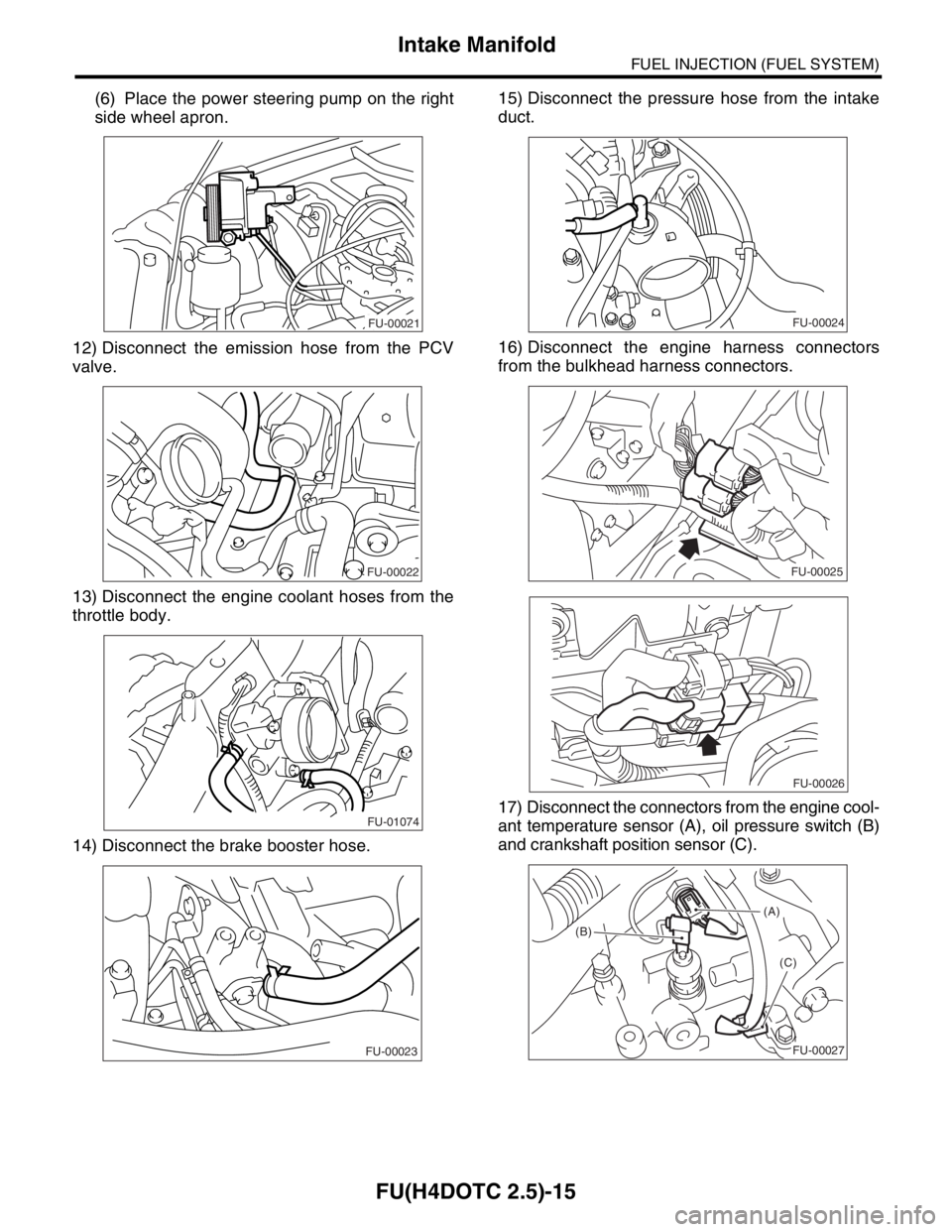
(6) Place the power steering pump on the right
side wheel apron.
12) Disconnect the emission hose from the PCV
valve.
13) Disconnect the engine coolant hoses from the
throttle body.
14) Disconnect the brake booster hose.15) Disconnect the pressure hose from the intake
duct.
16) Disconnect the engine harness connectors
from the bulkhead harness connectors.
17) Disconnect the connectors from the engine cool-
ant temperature sensor (A), oil pressure switch (B)
and crankshaft position sensor (C).
FU-00021
FU-00022
FU-01074
FU-00023
FU-00024
FU-00025
FU-00026
(A)
(B)
(C)
FU-00027
Page 1947 of 2870
FU(H4DOTC 2.5)-17
FUEL INJECTION (FUEL SYSTEM)
Intake Manifold
B: INSTALLATION
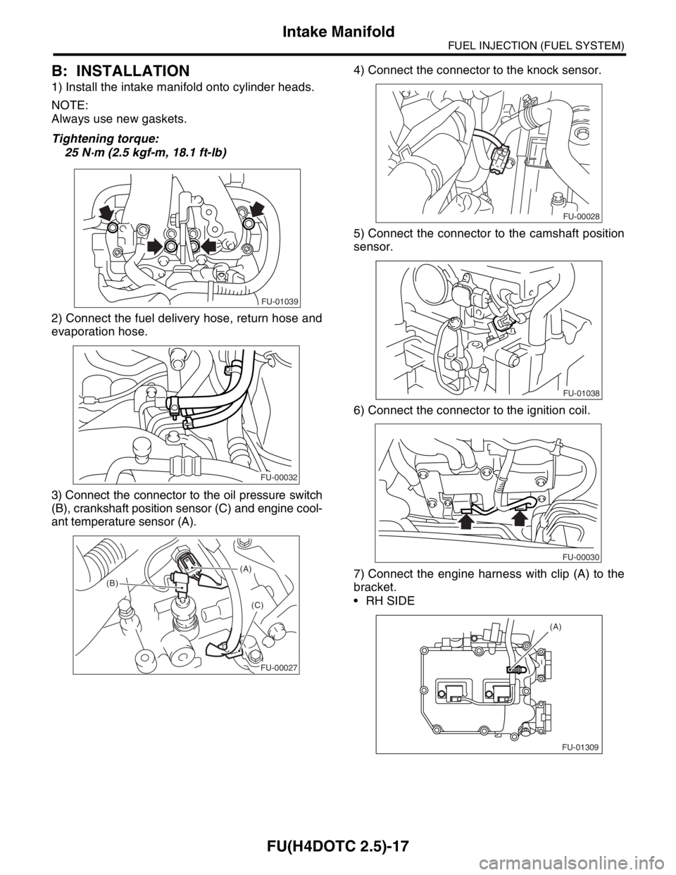
1) Install the intake manifold onto cylinder heads.
NOTE:
Always use new gaskets.
Tightening torque:
25 N·m (2.5 kgf-m, 18.1 ft-lb)
2) Connect the fuel delivery hose, return hose and
evaporation hose.
3) Connect the connector to the oil pressure switch
(B), crankshaft position sensor (C) and engine cool-
ant temperature sensor (A).4) Connect the connector to the knock sensor.
5) Connect the connector to the camshaft position
sensor.
6) Connect the connector to the ignition coil.
7) Connect the engine harness with clip (A) to the
bracket.
RH SIDE
FU-01039
FU-00032
(A)
(B)
(C)
FU-00027
FU-00028
FU-01038
FU-00030
FU-01309 (A)
Page 2283 of 2870

EN(H4DOTC 2.5)-259
ENGINE (DIAGNOSTIC)
General Diagnostic Table
*1: Check ignition coil & ignitor ASSY and spark plug.
*2: Indicate the symptom occurring only in cold temperatures.
*3: Ensure the secure installation.
*4: Check fuel injector, fuel pressure regulator and fuel filter.
*5: Inspect air leak in air intake system. 7. Spark knock1) Manifold absolute pressure sensor
2) Mass air flow and intake air temperature sensor
3) Engine coolant temperature sensor
4) Knock sensor
5) Fuel injection parts (*4)
6) Fuel pump and fuel pump relay
8. After burning in exhaust system1) Manifold absolute pressure sensor
2) Mass air flow and intake air temperature sensor
3) Engine coolant temperature sensor (*2)
4) Fuel injection parts (*4)
5) Fuel pump and fuel pump relay Symptom Problem parts
Page 2313 of 2870

AUTOMATIC TRANSMISSION
4AT
Page
1. General Description ....................................................................................2
2. Automatic Transmission Fluid ...................................................................30
3. Differential Gear Oil...................................................................................31
4. Road Test..................................................................................................32
5. Stall Test ...................................................................................................33
6. Time Lag Test ...........................................................................................35
7. Line Pressure Test ....................................................................................36
8. Transfer Clutch Pressure Test ..................................................................38
9. Automatic Transmission Assembly ...........................................................39
10. Transmission Mounting System ................................................................47
11. Extension Case Oil Seal ...........................................................................49
12. Differential Side Retainer Oil Seal.............................................................50
13. Inhibitor Switch ..........................................................................................51
14. Front Vehicle Speed Sensor .....................................................................55
15. Rear Vehicle Speed Sensor ......................................................................59
16. Torque Converter Turbine Speed Sensor .................................................60
17. Control Valve Body ...................................................................................61
18. Air Bleeding of Control Valve ....................................................................70
19.
Shift Solenoids, Duty Solenoids and ATF Temperature Sensor.........................71
20. Transfer Duty Solenoid and Valve Body ...................................................73
21. ATF Filter ..................................................................................................76
22. Transmission Control Module (TCM) ........................................................77
23. Dropping Resistor .....................................................................................78
24. ATF Cooler Pipe and Hose .......................................................................79
25. ATF Cooler (With Warmer Function).........................................................84
26. Air Breather Hose......................................................................................87
27. Oil Charger Pipe........................................................................................88
28. Torque Converter Clutch Assembly ..........................................................89
29. Extension Case .........................................................................................90
30. Transfer Clutch..........................................................................................92
31. Reduction Driven Gear..............................................................................97
32. Reduction Drive Gear................................................................................99
33. Parking Pawl ...........................................................................................101
34. Torque Converter Clutch Case ...............................................................102
35. Oil Pump Housing ...................................................................................105
36. Drive Pinion Shaft Assembly ...................................................................111
37. Front Differential......................................................................................117
38. AT Main Case .........................................................................................123
39. Transmission Control Device ..................................................................142
Page 2316 of 2870
4AT-4
AUTOMATIC TRANSMISSION
General Description
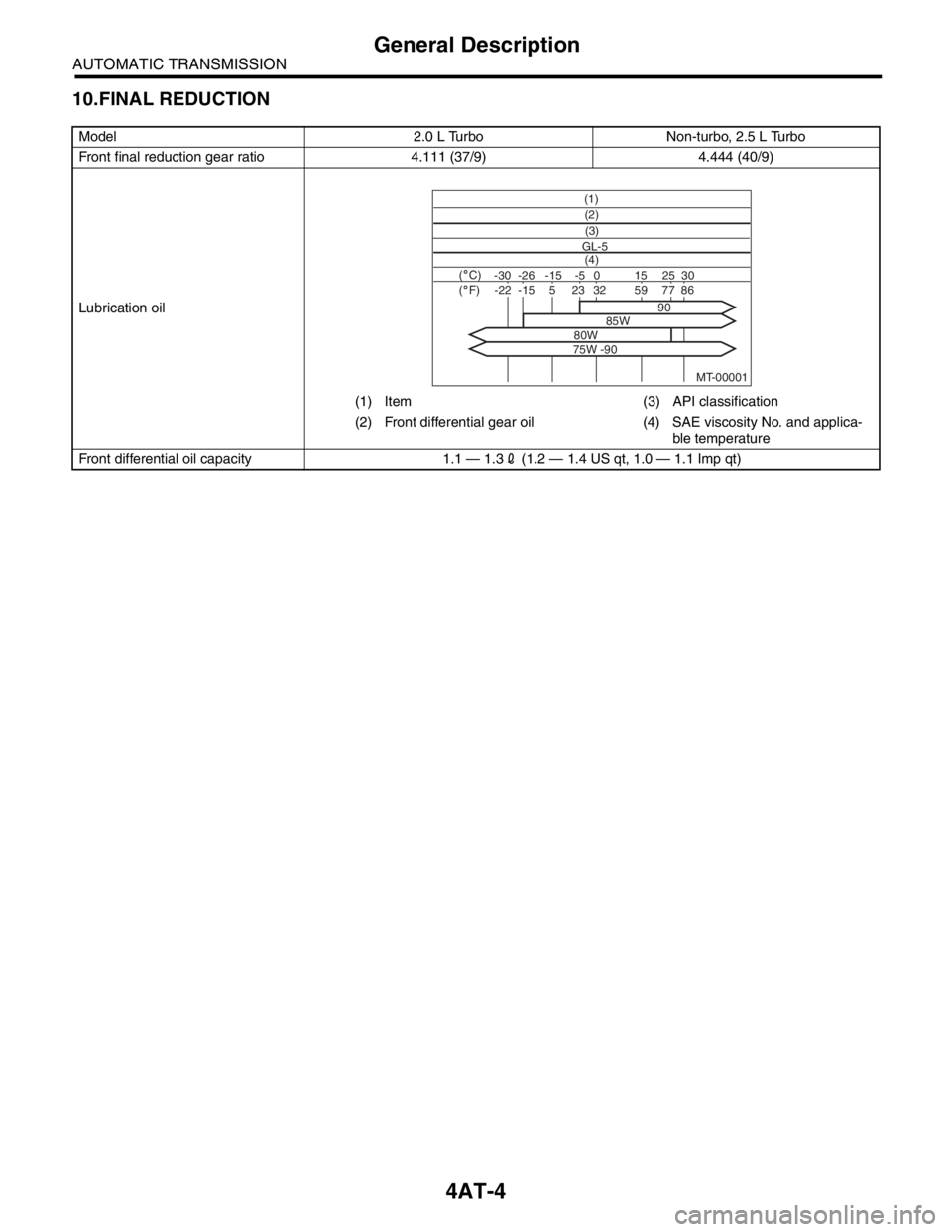
10.FINAL REDUCTION
Model 2.0 L Turbo Non-turbo, 2.5 L Turbo
Front final reduction gear ratio 4.111 (37/9) 4.444 (40/9)
Lubrication oil
(1) Item (3) API classification
(2) Front differential gear oil (4) SAE viscosity No. and applica-
ble temperature
Front differential oil capacity 1.1 — 1.32 (1.2 — 1.4 US qt, 1.0 — 1.1 Imp qt)
MT-00001
(1)
(4) GL-5(3) (2)
( C)( F)-30 -26 -15 15
90
85W
80W
75W -9025 30 -5 0-22-1523328659775