oil temperature SUBARU FORESTER 2004 Service User Guide
[x] Cancel search | Manufacturer: SUBARU, Model Year: 2004, Model line: FORESTER, Model: SUBARU FORESTER 2004Pages: 2870, PDF Size: 38.67 MB
Page 745 of 2870
PM-8
PERIODIC MAINTENANCE SERVICE
Engine Oil
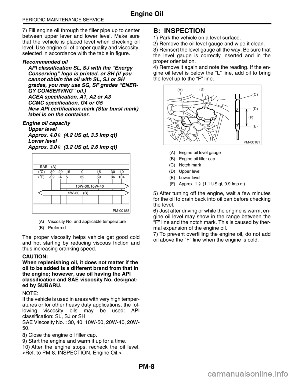
7) Fill engine oil through the filler pipe up to center
between upper lever and lower level. Make sure
that the vehicle is placed level when checking oil
level. Use engine oil of proper quality and viscosity,
selected in accordance with the table in figure.
Recommended oil
API classification SL, SJ with the “Energy
Conserving” logo is printed, or SH (if you
cannot obtain the oil with SL, SJ or SH
grades, you may use SG, SF grades “ENER-
GY CONSERVING” oil.)
ACEA specification, A1, A2 or A3
CCMC specification, G4 or G5
New API certification mark (Star burst mark)
label is on the container.
Engine oil capacity
Upper level
Approx. 4.02 (4.2 US qt, 3.5 Imp qt)
Lower level
Approx. 3.02 (3.2 US qt, 2.6 Imp qt)
The proper viscosity helps vehicle get good cold
and hot starting by reducing viscous friction and
thus increasing cranking speed.
CAUTION:
When replenishing oil, it does not matter if the
oil to be added is a different brand from that in
the engine; however, use oil having the API
classification and SAE viscosity No. designat-
ed by SUBARU.
NOTE:
If the vehicle is used in areas with very high temper-
atures or for other heavy duty applications, the fol-
lowing viscosity oils may be used: API
classification: SL, SJ or SH
SAE Viscosity No. : 30, 40, 10W-50, 20W-40, 20W-
50.
8) Close the engine oil filler cap.
9) Start the engine and warm it up for a time.
10) After the engine stops, recheck the oil level.
1) Park the vehicle on a level surface.
2) Remove the oil level gauge and wipe it clean.
3) Reinsert the level gauge all the way. Be sure that
the level gauge is correctly inserted and in the
proper orientation.
4) Remove it again and note the reading. If the en-
gine oil level is below the “L” line, add oil to bring
the level up to the “F” line.
5) After turning off the engine, wait a few minutes
for the oil to drain back into oil pan before checking
the level.
6) Just after driving or while the engine is warm, en-
gine oil level may show in the range between the
“F” line and the notch mark. This is caused by ther-
mal expansion of the engine oil.
7) To prevent overfilling the engine oil, do not add
oil above the “F” line when the engine is cold.
(A) Viscosity No. and applicable temperature
(B) Preferred
PM-00188
40 30 15 0 -15 -20 -30 ( C)
104 86 59 32
10W-30,10W-40 5 -4 -22 ( F)
SAE (A)
5W-30 (B)
(A) Engine oil level gauge
(B) Engine oil filler cap
(C) Notch mark
(D) Upper level
(E) Lower level
(F) Approx. 12 (1.1 US qt, 0.9 Imp qt)
PM-00181
(A)(B)
(D)
(E) (F)(C)
Page 763 of 2870
PM-26
PERIODIC MAINTENANCE SERVICE
ATF
16.ATF
A: INSPECTION
CAUTION:
The level of ATF varies with fluid temperature.
Pay attention to the fluid temperature when
checking ATF level.
1) Raise the ATF temperature by driving a distance
of 5 to 10 km (3 to 6 miles). Otherwise, idle the en-
gine to raise ATF temperature to 70 — 80°C (158
— 176°F) on Subaru Select Monitor.
TION, Subaru Select Monitor.>
2) Make sure the vehicle is level.
3) After selecting all positions (P, R, N, D, 3, 2, 1),
set the select lever in “P” range. Measure the ATF
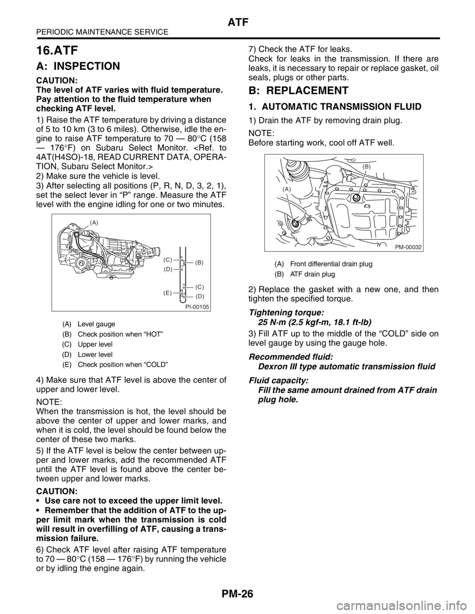
level with the engine idling for one or two minutes.
4) Make sure that ATF level is above the center of
upper and lower level.
NOTE:
When the transmission is hot, the level should be
above the center of upper and lower marks, and
when it is cold, the level should be found below the
center of these two marks.
5) If the ATF level is below the center between up-
per and lower marks, add the recommended ATF
until the ATF level is found above the center be-
tween upper and lower marks.
CAUTION:
Use care not to exceed the upper limit level.
Remember that the addition of ATF to the up-
per limit mark when the transmission is cold
will result in overfilling of ATF, causing a trans-
mission failure.
6) Check ATF level after raising ATF temperature
to 70 — 80°C (158 — 176°F) by running the vehicle
or by idling the engine again.7) Check the ATF for leaks.
Check for leaks in the transmission. If there are
leaks, it is necessary to repair or replace gasket, oil
seals, plugs or other parts.
B: REPLACEMENT
1. AUTOMATIC TRANSMISSION FLUID
1) Drain the ATF by removing drain plug.
NOTE:
Before starting work, cool off ATF well.
2) Replace the gasket with a new one, and then
tighten the specified torque.
Tightening torque:
25 N·m (2.5 kgf-m, 18.1 ft-lb)
3) Fill ATF up to the middle of the “COLD” side on
level gauge by using the gauge hole.
Recommended fluid:
Dexron III type automatic transmission fluid
Fluid capacity:
Fill the same amount drained from ATF drain
plug hole.
(A) Level gauge
(B) Check position when “HOT”
(C) Upper level
(D) Lower level
(E) Check position when “COLD”
PI-00105
COLD
LFHOT LF
(A)
(C)
(D)
(C)
(D)
(E)
(B)(A) Front differential drain plug
(B) ATF drain plug
PM-00032
(B)
(A)
Page 765 of 2870
PM-28
PERIODIC MAINTENANCE SERVICE
Front & Rear Differential Oil
17.Front & Rear Differential Oil
A: REPLACEMENT
1. FRONT DIFFERENTIAL (MT MODEL)
For MT model, manual transmission oil works as
differential oil to lubricate differential. Refer to
“Transmission Oil”.
2. FRONT DIFFERENTIAL (AT MODEL)
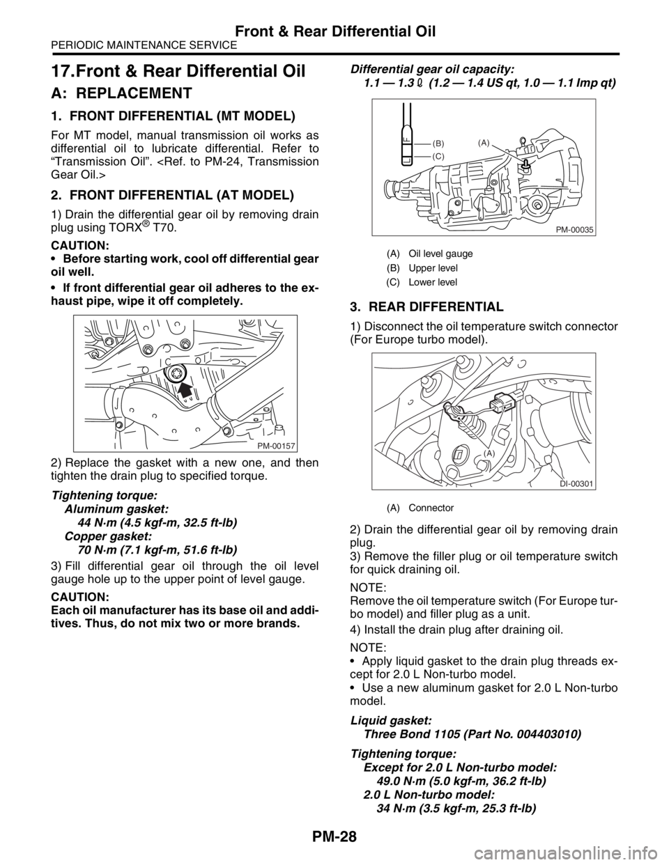
1) Drain the differential gear oil by removing drain
plug using TORX® T70.
CAUTION:
Before starting work, cool off differential gear
oil well.
If front differential gear oil adheres to the ex-
haust pipe, wipe it off completely.
2) Replace the gasket with a new one, and then
tighten the drain plug to specified torque.
Tightening torque:
Aluminum gasket:
44 N·m (4.5 kgf-m, 32.5 ft-lb)
Copper gasket:
70 N·m (7.1 kgf-m, 51.6 ft-lb)
3) Fill differential gear oil through the oil level
gauge hole up to the upper point of level gauge.
CAUTION:
Each oil manufacturer has its base oil and addi-
tives. Thus, do not mix two or more brands.Differential gear oil capacity:
1.1 — 1.32 (1.2 — 1.4 US qt, 1.0 — 1.1 Imp qt)
3. REAR DIFFERENTIAL
1) Disconnect the oil temperature switch connector
(For Europe turbo model).
2) Drain the differential gear oil by removing drain
plug.
3) Remove the filler plug or oil temperature switch
for quick draining oil.
NOTE:
Remove the oil temperature switch (For Europe tur-
bo model) and filler plug as a unit.
4) Install the drain plug after draining oil.
NOTE:
Apply liquid gasket to the drain plug threads ex-
cept for 2.0 L Non-turbo model.
Use a new aluminum gasket for 2.0 L Non-turbo
model.
Liquid gasket:
Three Bond 1105 (Part No. 004403010)
Tightening torque:
Except for 2.0 L Non-turbo model:
49.0 N·m (5.0 kgf-m, 36.2 ft-lb)
2.0 L Non-turbo model:
34 N·m (3.5 kgf-m, 25.3 ft-lb)
PM-00157
(A) Oil level gauge
(B) Upper level
(C) Lower level
(A) Connector
PM-00035
(B)
(C)(A)
DI-00301
(A)
Page 766 of 2870
PM-29
PERIODIC MAINTENANCE SERVICE
Front & Rear Differential Oil
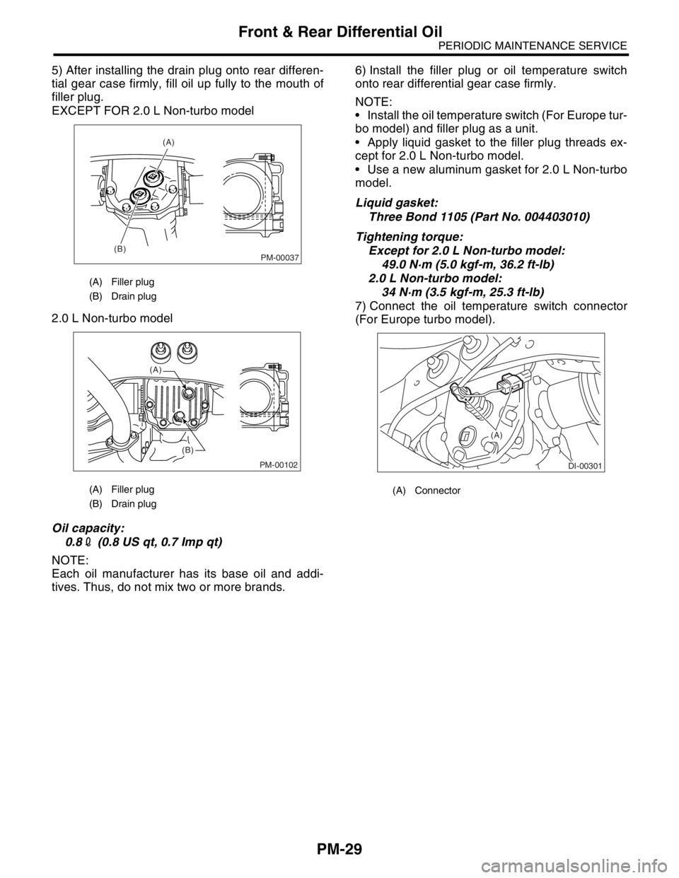
5) After installing the drain plug onto rear differen-
tial gear case firmly, fill oil up fully to the mouth of
filler plug.
EXCEPT FOR 2.0 L Non-turbo model
2.0 L Non-turbo model
Oil capacity:
0.82 (0.8 US qt, 0.7 Imp qt)
NOTE:
Each oil manufacturer has its base oil and addi-
tives. Thus, do not mix two or more brands.6) Install the filler plug or oil temperature switch
onto rear differential gear case firmly.
NOTE:
Install the oil temperature switch (For Europe tur-
bo model) and filler plug as a unit.
Apply liquid gasket to the filler plug threads ex-
cept for 2.0 L Non-turbo model.
Use a new aluminum gasket for 2.0 L Non-turbo
model.
Liquid gasket:
Three Bond 1105 (Part No. 004403010)
Tightening torque:
Except for 2.0 L Non-turbo model:
49.0 N·m (5.0 kgf-m, 36.2 ft-lb)
2.0 L Non-turbo model:
34 N·m (3.5 kgf-m, 25.3 ft-lb)
7) Connect the oil temperature switch connector
(For Europe turbo model).
(A) Filler plug
(B) Drain plug
(A) Filler plug
(B) Drain plug
PM-00037
(A)
(B)
PM-00102
(A)
(B)
(A) Connector
DI-00301
(A)
Page 779 of 2870
PM-42
PERIODIC MAINTENANCE SERVICE
Steering System (Power Steering)
(2) Retighten the adjusting screw to 7.4 N·m
(0.75 kgf-m, 5.4 ft-lb) and back off 25°.
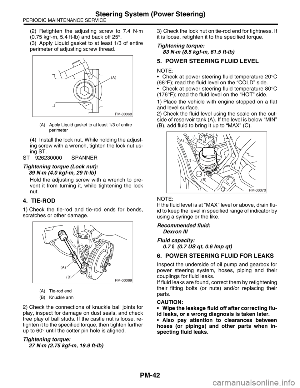
(3) Apply Liquid gasket to at least 1/3 of entire
perimeter of adjusting screw thread.
(4) Install the lock nut. While holding the adjust-
ing screw with a wrench, tighten the lock nut us-
ing ST.
ST 926230000 SPANNER
Tightening torque (Lock nut):
39 N·m (4.0 kgf-m, 29 ft-lb)
Hold the adjusting screw with a wrench to pre-
vent it from turning it, while tightening the lock
nut.
4. TIE-ROD
1) Check the tie-rod and tie-rod ends for bends,
scratches or other damage.
2) Check the connections of knuckle ball joints for
play, inspect for damage on dust seals, and check
free play of ball studs. If the castle nut is loose, re-
tighten it to the specified torque, then tighten further
up to 60° until the cotter pin hole is aligned.
Tightening torque:
27 N·m (2.75 kgf-m, 19.9 ft-lb)3) Check the lock nut on tie-rod end for tightness. If
it is loose, retighten it to the specified torque.
Tightening torque:
83 N·m (8.5 kgf-m, 61.5 ft-lb)
5. POWER STEERING FLUID LEVEL
NOTE:
Check at power steering fluid temperature 20°C
(68°F); read the fluid level on the “COLD” side.
Check at power steering fluid temperature 80°C
(176°F); read the fluid level on the “HOT” side.
1) Place the vehicle with engine stopped on a flat
and level surface.
2) Check the fluid level using the scale on the out-
side of reservoir tank (A). If the level is below “MIN”
(B), add fluid to bring it up to “MAX” (C).
NOTE:
If the fluid level is at “MAX” level or above, drain flu-
id to keep the level in specified range of indicator by
using a syringe or the like.
Recommended fluid:
Dexron III
Fluid capacity:
0.72 (0.7 US qt, 0.6 Imp qt)
6. POWER STEERING FLUID FOR LEAKS
Inspect the underside of oil pump and gearbox for
power steering system, hoses, piping and their
couplings for fluid leaks.
If fluid leaks are found, correct them by retightening
their fitting bolts (or nuts) and/or replacing their
parts.
CAUTION:
Wipe the leakage fluid off after correcting flu-
id leaks, or a wrong diagnosis is taken later.
Also pay attention to clearances between
hoses (or pipings) and other parts when in-
specting fluid leaks.
(A) Apply Liquid gasket to at least 1/3 of entire
perimeter
(A) Tie-rod end
(B) Knuckle arm
PM-00068
(A)
PM-00069
(A)
(B)
PM-00070
(A)
(C)
(B)
Page 799 of 2870
FU(H4SO)-17
FUEL INJECTION (FUEL SYSTEM)
Intake Manifold
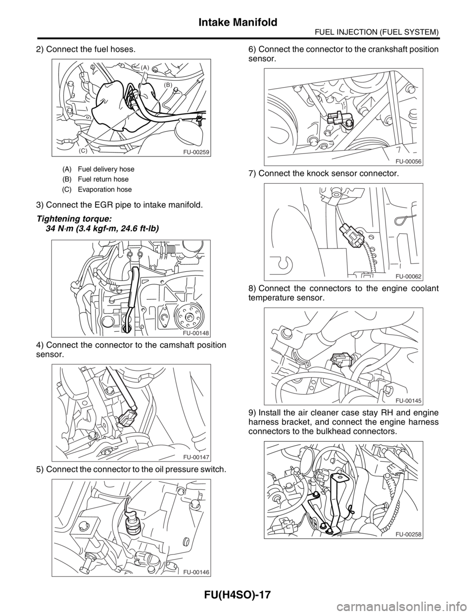
2) Connect the fuel hoses.
3) Connect the EGR pipe to intake manifold.
Tightening torque:
34 N
⋅m (3.4 kgf-m, 24.6 ft-lb)
4) Connect the connector to the camshaft position
sensor.
5) Connect the connector to the oil pressure switch.6) Connect the connector to the crankshaft position
sensor.
7) Connect the knock sensor connector.
8) Connect the connectors to the engine coolant
temperature sensor.
9) Install the air cleaner case stay RH and engine
harness bracket, and connect the engine harness
connectors to the bulkhead connectors.
(A) Fuel delivery hose
(B) Fuel return hose
(C) Evaporation hose
(B) (A)
(C)
FU-00259
FU-00148
FU-00147
FU-00146
FU-00056
FU-00062
FU-00145
FU-00258
Page 957 of 2870
ME(H4SO)-86
MECHANICAL
Cylinder Block
NOTE:
Immediately after reboring, the cylinder diameter
may differ from its real diameter due to temperature
rise. Thus, pay attention to this when measuring
the cylinder diameter.
Limit of cylinder enlarging (boring):
0.5 mm (0.020 in)
3. PISTON AND PISTON PIN
1) Check the pistons and piston pins for damage,
cracks, and wear and the piston ring grooves for
wear and damage. Replace if defective.
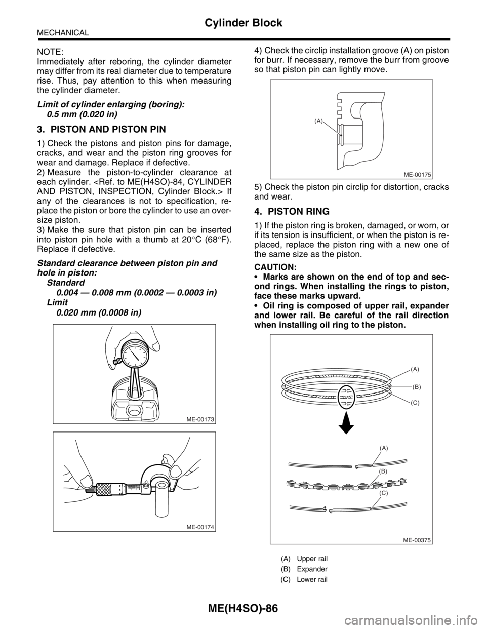
2) Measure the piston-to-cylinder clearance at
each cylinder.
any of the clearances is not to specification, re-
place the piston or bore the cylinder to use an over-
size piston.
3) Make the sure that piston pin can be inserted
into piston pin hole with a thumb at 20°C (68°F).
Replace if defective.
Standard clearance between piston pin and
hole in piston:
Standard
0.004 — 0.008 mm (0.0002 — 0.0003 in)
Limit
0.020 mm (0.0008 in)4) Check the circlip installation groove (A) on piston
for burr. If necessary, remove the burr from groove
so that piston pin can lightly move.
5) Check the piston pin circlip for distortion, cracks
and wear.
4. PISTON RING
1) If the piston ring is broken, damaged, or worn, or
if its tension is insufficient, or when the piston is re-
placed, replace the piston ring with a new one of
the same size as the piston.
CAUTION:
Marks are shown on the end of top and sec-
ond rings. When installing the rings to piston,
face these marks upward.
Oil ring is composed of upper rail, expander
and lower rail. Be careful of the rail direction
when installing oil ring to the piston.
ME-00173
ME-00174
(A) Upper rail
(B) Expander
(C) Lower rail
ME-00175
(A)
ME-00375(A)
(B)
(C)
(A)
(B)
(C)
Page 985 of 2870

CO(H4SO)-2
COOLING
General Description
1. General Description
A: SPECIFICATION
ModelNon-turbo Turbo
Cooling system Electric fan+Forced engine coolant circulation system
Total engine coolant capacity2(US qt, Imp qt)2.0L with ATF warmer:
Approx. 6.9 (7.29, 6.07)
2.0L AT:
Approx. 6.5 (6.87, 5.72)
2.0L MT:
Approx. 6.6 (6.98, 5.81)
2.5L AT:
Approx. 6.8 (7.19, 5.98)
2.5L MT:
Approx. 6.9 (7.29, 6.07)AT :
Approx. 7.3 (7.71, 6.42)
MT with oil cooler:
Approx. 7.3 (7.71, 6.42)
MT without oil cooler:
Approx. 7.4 (7.82, 6.51)
Water pumpType Centrifugal impeller type
Discharge perfor-
mance IDischarge 202 (5.3 US gal, 4.4 Imp gal)/min.
Pump speed — Discharge
pressure760 rpm — 2.9 kPa (0.3 mAq)
Engine coolant temperature 85°C (185°F)
Discharge perfor-
mance IIDischarge 1002 (26.4 US gal, 22.0 Imp gal)/min.
Pump speed — Discharge
pressure3,000 rpm — 49.0 kPa (5.0 mAq)
Engine coolant temperature 85°C (185°F)
Discharge perfor-
mance IIIDischarge 2002 (52.8 US gal, 44.0 Imp gal)/min.
Pump speed — Discharge
pressure6,000 rpm — 225.4 kPa (23.0 mAq)
Engine coolant temperature 85°C (185°F)
Impeller diameter 76 mm (2.99 in)
Number of impeller vanes 8
Pump pulley diameter 60 mm (2.36 in)
Clearance between
impeller and caseStandard 0.5 — 0.7 mm (0.020 — 0.028 in)
Limit 1.0 mm (0.039 in)
“Thrust” runout of impeller end 0.5 mm (0.020 in)
ThermostatType Wax pellet type
Starts to open 80 — 84°C (176 — 183°F) 76 — 80°C (169 — 176°F)
Fully opened 95°C (203°F) 91°C (196°F)
Valve lift 9.0 mm (0.354 in) or more
Valve bore 35 mm (1.38 in)
Radiator fanMotorMain fan 70 W2.0L AT (K4
★1) : 70 W
2.0L AT (EC, EK★1) :
120 W
2.0 L MT: 70 W
2.5 L: 120 W
Sub fan 70 W2.0L AT (K4
★1) : 70 W
2.0L AT (EC, EK★1) :
120 W
2.0 L MT: 70 W
2.5 L: 120 W
Fan diameter×Blade320 mm (11.81 in)×5 (main fan)
320 mm (11.81 in)×7 (sub fan)
Page 1026 of 2870

CO(H4SO)-43
COOLING
Engine Cooling System Trouble in General
12.Engine Cooling System Trouble in General
A: INSPECTION
Trouble Possible cause Corrective action
Over-heatinga. Insufficient engine coolantReplenish the engine coolant, inspect for leakage, and
repair.
b. Loose timing belt Repair or replace the timing belt tensioner.
c. Oil on drive belt Replace.
d. Malfunction of thermostat Replace.
e. Malfunction of water pump Replace.
f. Clogged engine coolant passage Clean.
g. Improper ignition timingInspect and repair the ignition control system.
h. Clogged or leaking radiator Clean or repair, or replace.
i. Improper engine oil in engine coolant Replace the engine coolant.
j. Air/fuel mixture ratio too leanInspect and repair the fuel injection system.
k. Excessive back pressure in exhaust system Clean or replace.
l. Insufficient clearance between piston and cylinder Adjust or replace.
m. Slipping clutch Repair or replace.
n. Dragging brake Adjust.
o. Defective thermostat Replace.
p. Malfunction of radiator fanInspect the radiator fan relay, engine coolant tempera-
ture sensor or radiator motor and replace there.
Over-coolinga. Atmospheric temperature extremely low Partly cover the radiator front area.
b. Defective thermostat Replace.
Engine coolant
leaks.a. Loosened or damaged connecting units on hoses Repair or replace.
b. Leakage from water pump Replace.
c. Leakage from water pipe Repair or replace.
d. Leakage around cylinder head gasket Retighten the cylinder head bolts or replace gasket.
e. Damaged or cracked cylinder head and crankcase Repair or replace.
f. Damaged or cracked thermostat case Repair or replace.
g. Leakage from radiator Repair or replace.
Noisea. Defective drive belt Replace.
b. Defective radiator fan Replace.
c. Defective water pump bearing Replace the water pump.
d. Defective water pump mechanical seal Replace the water pump.
Page 1039 of 2870
LU(H4SO)-11
LUBRICATION
Engine Oil
6) Tighten the engine oil drain plug after draining
engine oil.
Tightening torque:
44 N
⋅m (4.5 kgf-m, 32.5 ft-lb)
7) Install the service hole cover.
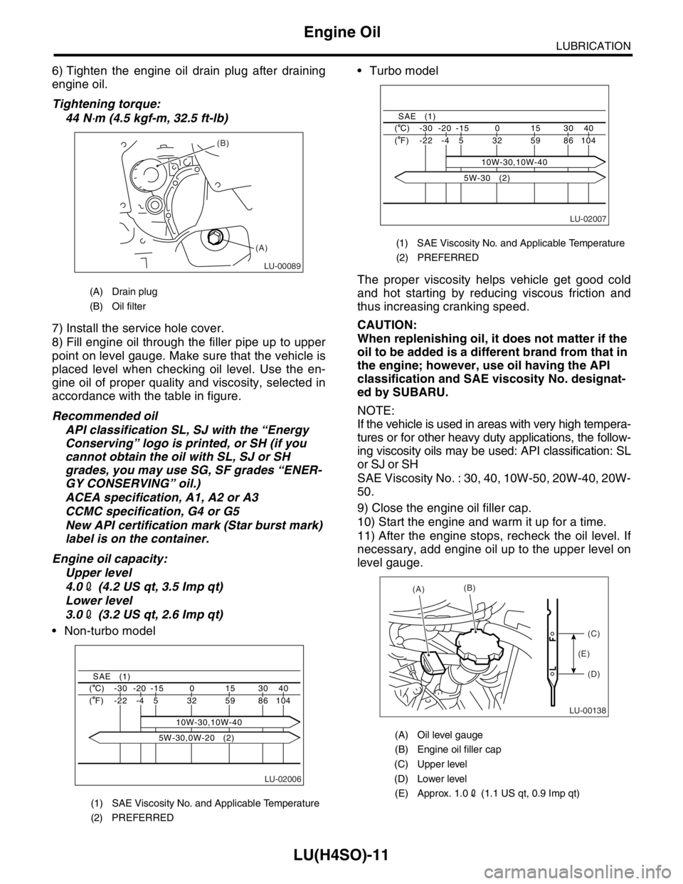
8) Fill engine oil through the filler pipe up to upper
point on level gauge. Make sure that the vehicle is
placed level when checking oil level. Use the en-
gine oil of proper quality and viscosity, selected in
accordance with the table in figure.
Recommended oil
API classification SL, SJ with the “Energy
Conserving” logo is printed, or SH (if you
cannot obtain the oil with SL, SJ or SH
grades, you may use SG, SF grades “ENER-
GY CONSERVING” oil.)
ACEA specification, A1, A2 or A3
CCMC specification, G4 or G5
New API certification mark (Star burst mark)
label is on the container.
Engine oil capacity:
Upper level
4.02 (4.2 US qt, 3.5 Imp qt)
Lower level
3.02 (3.2 US qt, 2.6 Imp qt)
Non-turbo model Turbo model
The proper viscosity helps vehicle get good cold
and hot starting by reducing viscous friction and
thus increasing cranking speed.
CAUTION:
When replenishing oil, it does not matter if the
oil to be added is a different brand from that in
the engine; however, use oil having the API
classification and SAE viscosity No. designat-
ed by SUBARU.
NOTE:
If the vehicle is used in areas with very high tempera-
tures or for other heavy duty applications, the follow-
ing viscosity oils may be used: API classification: SL
or SJ or SH
SAE Viscosity No. : 30, 40, 10W-50, 20W-40, 20W-
50.
9) Close the engine oil filler cap.
10) Start the engine and warm it up for a time.
11) After the engine stops, recheck the oil level. If
necessary, add engine oil up to the upper level on
level gauge.
(A) Drain plug
(B) Oil filter
(1) SAE Viscosity No. and Applicable Temperature
(2) PREFERRED
LU-00089
(B)
(A)
LU-02006
40 30 15 0 -15 -20 -30 ( C)
104 86 59 32
10W-30,10W-40 5 -4 -22 ( F)
SAE (1)
5W-30,0W-20 (2)
(1) SAE Viscosity No. and Applicable Temperature
(2) PREFERRED
(A) Oil level gauge
(B) Engine oil filler cap
(C) Upper level
(D) Lower level
(E) Approx. 1.02 (1.1 US qt, 0.9 Imp qt)
LU-02007
40 30 15 0 -15 -20 -30 ( C)
104 86 59 32 5 -4 -22 ( F)
SAE (1)
10W-30,10W-40
5W-30 (2)
LU-00138
(A)(B)
(C)
(D) (E)