SUBARU FORESTER 2004 Service Repair Manual
Manufacturer: SUBARU, Model Year: 2004, Model line: FORESTER, Model: SUBARU FORESTER 2004Pages: 2870, PDF Size: 38.67 MB
Page 391 of 2870

IDI-7
INSTRUMENTATION/DRIVER INFO
Combination Meter System
5. CHECK ENGINE CONTROL MODULE (ECM)
6. CHECK FUEL LEVEL SENSOR
Step Check Yes No
1 CHECK ECM SIGNAL.
1) Start the engine.
2) Measure the voltage between ECM con-
nector and engine ground.
Connector & terminal
Non-turbo model
(B134) No. 10 (+) — Engine ground (
−):
Turbo model
(B134) No. 23 (+) — Engine ground (
−):Is the voltage 0 V ← → 14 V? Go to step 2.Check ECM.
Basic Diagnostics
Procedure.>
Basic Diagnostics
Procedure.>
2 CHECK HARNESS BETWEEN COMBINA-
TION METER AND ECM.
1) Turn the ignition switch to OFF.
2) Disconnect the connector from ECM and
combination meter.
3) Measure the resistance between ECM har-
ness connector and combination meter har-
ness connector.
Connector & terminal
Non-turbo model
(B134) No. 10 — (i10) No. 11:
Turbo model
(B134) No. 23 — (i10) No. 11:Is the resistance less than 10
Ω?Check the tachom-
eter.
Tachometer.>Repair the wiring
harness.
Step Check Yes No
1 CHECK FUEL LEVEL SENSOR.
1) Remove the fuel level sensor.
sor.>
2) Measure the resistance between fuel level
sensor terminals when setting the float to
FULL and EMPTY position.
Te r m i n a l s
No. 3 — No. 5:Is the resistance 0.5 to 2.5 Ω
(FULL) and 50 to 52 Ω
(EMPTY)?Go to step 2.Replace the fuel
level sensor.
2 CHECK FUEL SUB LEVEL SENSOR.
1) Remove the fuel sub level sensor.
Sensor.>
2) Measure the resistance between fuel sub
level sensor terminals when setting the float to
FULL and EMPTY position.
Te r m i n a l s
No. 1 — No. 2:Is the resistance 0.5 to 2.5 Ω
(FULL) and 42 to 44 Ω
(EMPTY)?Go to step 3.Replace the fuel
sub level sensor.
3 CHECK HARNESS BETWEEN FUEL SUB
LEVEL SENSOR AND COMBINATION
METER.
1) Disconnect the connector from combination
meter.
2) Measure the resistance between fuel sub
level sensor harness connector terminal and
combination meter harness connector termi-
nal.
Connector & terminal
(R59) No. 1 — (i11) No. 1:Is the resistance less than 10
Ω?Go to step 4.Repair the wiring
harness.
Page 392 of 2870

IDI-8
INSTRUMENTATION/DRIVER INFO
Combination Meter System
7. CHECK ENGINE COOLANT TEMPERATURE SENSOR
8. CHECK OUTSIDE TEMPERATURE INDICATOR
4 CHECK HARNESS BETWEEN FUEL LEVEL
SENSOR AND FUEL SUB LEVEL SENSOR.
Measure the resistance between fuel level sen-
sor harness connector terminal and fuel sub
level sensor harness connector terminal.
Connector & terminal
(R58) No. 3 — (R59) No. 2:Is the resistance less than 10
Ω?Go to step 5.Repair the wiring
harness.
5 CHECK FUEL LEVEL SENSOR GROUND
CIRCUIT.
Measure the resistance between fuel level sen-
sor harness connector terminal and chassis
ground.
Connector & terminal
(R58) No. 5 — Chassis ground:Is the resistance less than 10
Ω?Check the fuel
gauge.
TION, Fuel
Gauge.>Repair the wiring
harness.
Step Check Yes No
1 CHECK ENGINE COOLANT TEMPERATURE
SENSOR.
Check the engine coolant temperature sensor.
ture sensor OK?Go to step 2.Replace the
engine coolant
temperature sen-
sor.
2 CHECK HARNESS BETWEEN ENGINE
COOLANT TEMPERATURE SENSOR AND
COMBINATION METER.
1) Turn the ignition switch to OFF.
2) Disconnect the connector from engine cool-
ant temperature sensor and combination
meter.
3) Measure the resistance between engine
coolant temperature sensor harness connector
and combination meter harness connector.
Connector & terminal
(E8) No. 3 — (i11) No. 10:Is the resistance less than 10
Ω?Go to step 3.Repair the wiring
harness.
3 CHECK WATER TEMPERATURE GAUGE
GROUND CIRCUIT.
Measure the resistance between combination
meter harness connector terminal and chassis
ground.
Connector & terminal
(i11) No. 9 — Chassis ground:Is the resistance less than 10
Ω?Check the water
temperature
gauge.
TION, Water Tem-
perature Gauge.>Repair the wiring
harness.
Step Check Yes No
1 CHECK POWER SUPPLY FOR AMBIENT
SENSOR.
1) Turn the ignition switch to OFF.
2) Disconnect the connector from outside
temperature sensor.
3) Turn the ignition switch to ON.
4) Measure the voltage between outside tem-
perature sensor harness connector terminal
and chassis ground.
Connector & terminal
(F78) No. 2 (+) — Chassis ground (
−):Is the voltage more than 4 V? Go to step 3.Go to step 2. Step Check Yes No
Page 393 of 2870

IDI-9
INSTRUMENTATION/DRIVER INFO
Combination Meter System
2 CHECK HARNESS BETWEEN AMBIENT
SENSOR AND COMBINATION METER.
1) Turn the ignition switch to OFF.
2) Disconnect the connector from combination
meter.
3) Measure the resistance between ambient
sensor harness connector terminal and combi-
nation meter harness connector terminal.
Connector & terminal
(F78) No. 1 — (i10) No. 25:
(F78) No. 2 — (i10) No. 24:Is the resistance less than 10
Ω?Replace the com-
bination meter
printed circuit.Repair the wiring
harness.
3 CHECK AMBIENT SENSOR.
1) Remove the ambient sensor.
2) Check the ambient sensor.
ent sensor.
4 CHECK OUTSIDE TEMPERATURE INDICA-
TOR.
1) Connect the combination meter harness
connector.
2) Connect a resistor (3 kΩ) between termi-
nals of ambient sensor harness connector.
3) Turn the ignition switch to ON and check
the outside temperature indicator display.Does the outside temperature
indicator indicate 25°C (77°F)?Repair the poor
contact of ambient
sensor harness
connector.Replace the com-
bination meter
printed circuit. Step Check Yes No
Page 394 of 2870
IDI-10
INSTRUMENTATION/DRIVER INFO
Combination Meter Assembly
3. Combination Meter Assem-
bly
A: REMOVAL
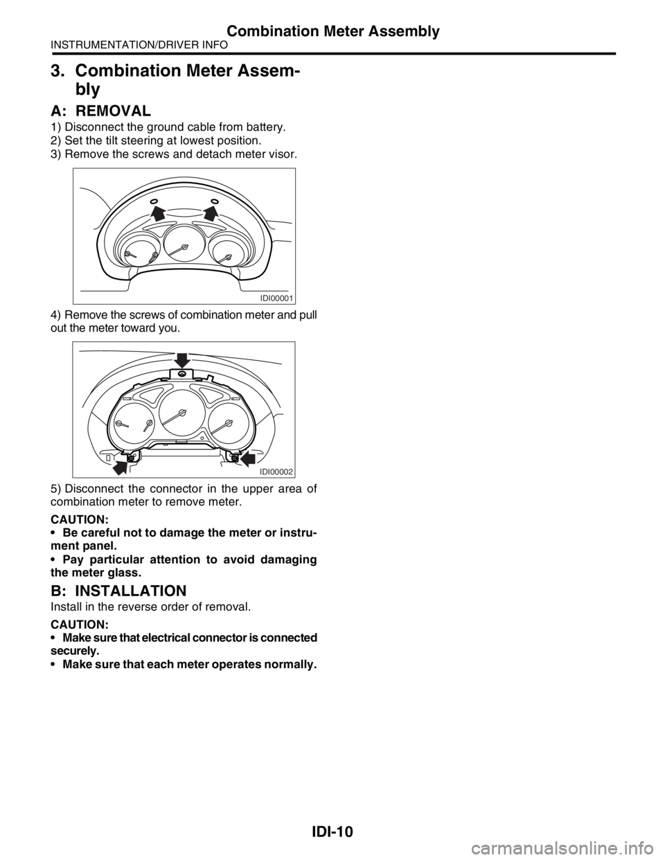
1) Disconnect the ground cable from battery.
2) Set the tilt steering at lowest position.
3) Remove the screws and detach meter visor.
4) Remove the screws of combination meter and pull
out the meter toward you.
5) Disconnect the connector in the upper area of
combination meter to remove meter.
CAUTION:
Be careful not to damage the meter or instru-
ment panel.
Pay particular attention to avoid damaging
the meter glass.
B: INSTALLATION
Install in the reverse order of removal.
CAUTION:
Make sure that electrical connector is connected
securely.
Make sure that each meter operates normally.
IDI00001
IDI00002
Page 395 of 2870
IDI-11
INSTRUMENTATION/DRIVER INFO
Combination Meter Assembly
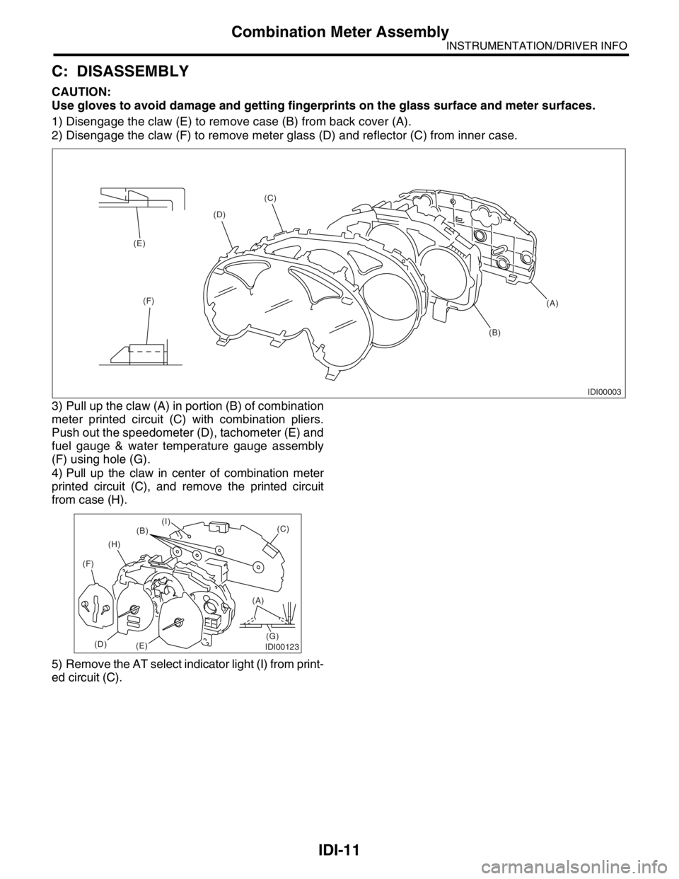
C: DISASSEMBLY
CAUTION:
Use gloves to avoid damage and getting fingerprints on the glass surface and meter surfaces.
1) Disengage the claw (E) to remove case (B) from back cover (A).
2) Disengage the claw (F) to remove meter glass (D) and reflector (C) from inner case.
3) Pull up the claw (A) in portion (B) of combination
meter printed circuit (C) with combination pliers.
Push out the speedometer (D), tachometer (E) and
fuel gauge & water temperature gauge assembly
(F) using hole (G).
4) Pull up the claw in center of combination meter
printed circuit (C), and remove the printed circuit
from case (H).
5) Remove the AT select indicator light (I) from print-
ed circuit (C).
IDI00003
(A) (C)
(D)
(E)
(F)
(B)
IDI00123
(A)
(G)(C)
(B)
(H)
(F)
(D)
(E)
(I)
Page 396 of 2870
IDI-12
INSTRUMENTATION/DRIVER INFO
Combination Meter Assembly
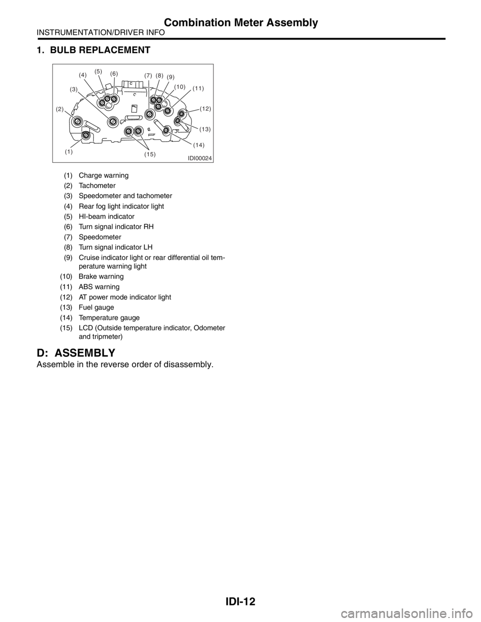
1. BULB REPLACEMENT
D: ASSEMBLY
Assemble in the reverse order of disassembly.
(1) Charge warning
(2) Tachometer
(3) Speedometer and tachometer
(4) Rear fog light indicator light
(5) HI-beam indicator
(6) Turn signal indicator RH
(7) Speedometer
(8) Turn signal indicator LH
(9) Cruise indicator light or rear differential oil tem-
perature warning light
(10) Brake warning
(11) ABS warning
(12) AT power mode indicator light
(13) Fuel gauge
(14) Temperature gauge
(15) LCD (Outside temperature indicator, Odometer
and tripmeter)
IDI00024(1) (2)(3)(5)
(6)
(7)(8)
(9)
(10)
(11)
(13)
(14)
(15)
(4)
(12)
Page 397 of 2870
IDI-13
INSTRUMENTATION/DRIVER INFO
Speedometer
4. Speedometer
A: REMOVAL
Disassemble the combination meter, and then re-
move the speedometer.
B: INSTALLATION
Install in the reverse order of removal.
C: INSPECTION
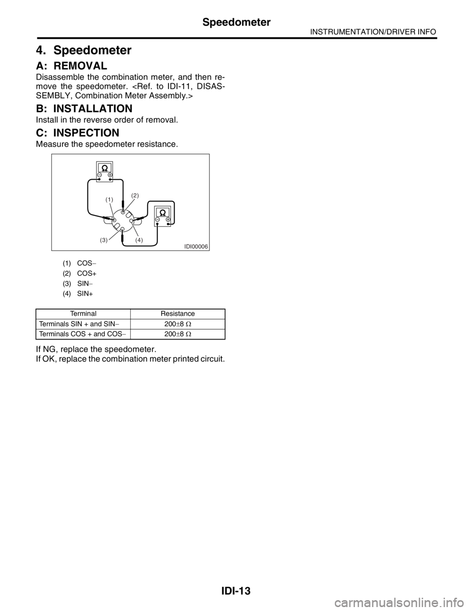
Measure the speedometer resistance.
If NG, replace the speedometer.
If OK, replace the combination meter printed circuit.
(1) COS−
(2) COS+
(3) SIN−
(4) SIN+
Terminal Resistance
Terminals SIN + and SIN−200±8 Ω
Terminals COS + and COS−200±8 Ω
IDI00006
(1)(2)
(4)
(3)
Page 398 of 2870
IDI-14
INSTRUMENTATION/DRIVER INFO
Tachometer
5. Tachometer
A: REMOVAL
Disassemble the combination meter, and then re-
move the tachometer.
B: INSTALLATION
Install in the reverse order of removal.
C: INSPECTION
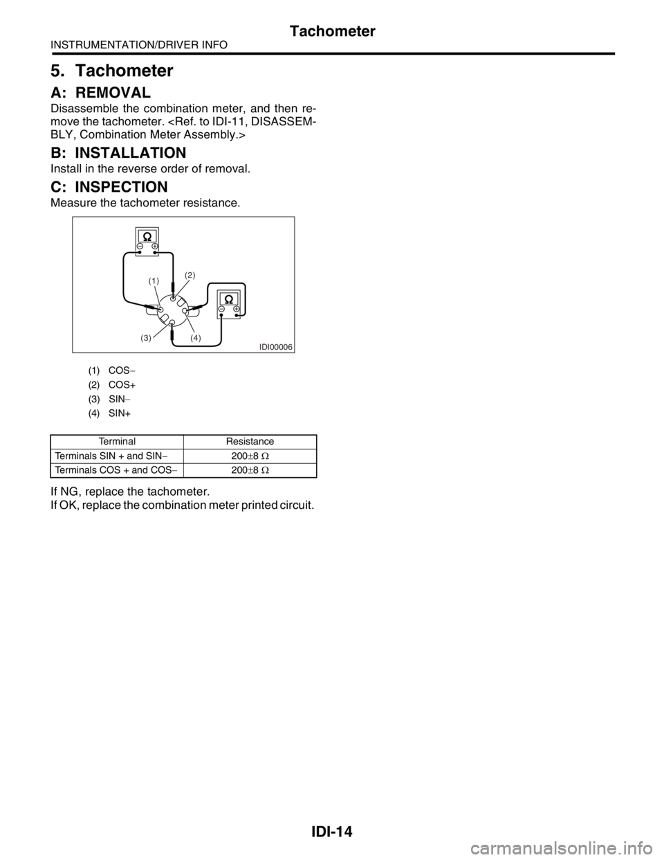
Measure the tachometer resistance.
If NG, replace the tachometer.
If OK, replace the combination meter printed circuit.
(1) COS−
(2) COS+
(3) SIN−
(4) SIN+
Terminal Resistance
Terminals SIN + and SIN−200±8 Ω
Terminals COS + and COS−200±8 Ω
IDI00006
(1)(2)
(4)
(3)
Page 399 of 2870
IDI-15
INSTRUMENTATION/DRIVER INFO
Fuel Gauge
6. Fuel Gauge
A: REMOVAL
Disassemble the combination meter, and then remove
the water temperature gauge and fuel gauge assem-
bly.
B: INSTALLATION
Install in the reverse order of removal.
C: INSPECTION
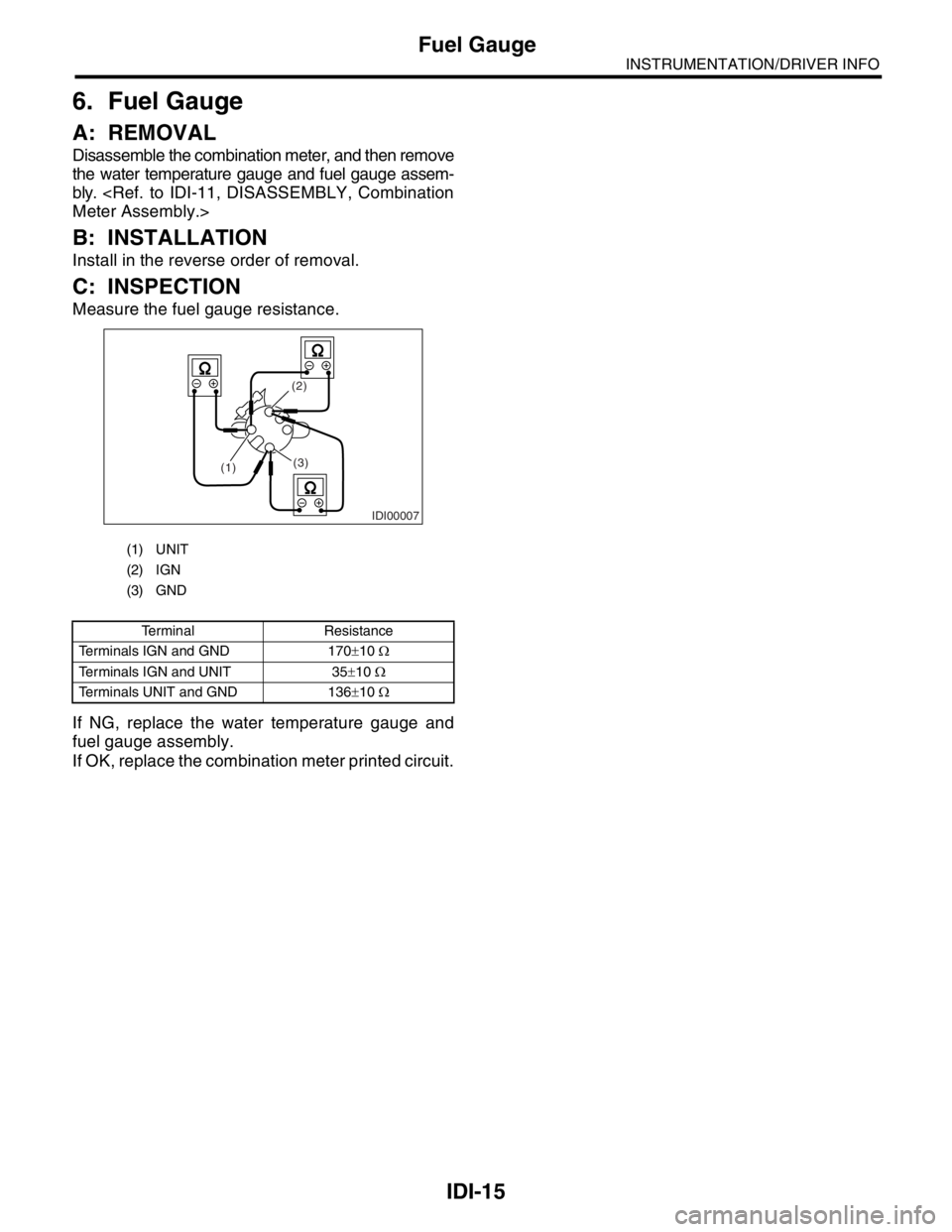
Measure the fuel gauge resistance.
If NG, replace the water temperature gauge and
fuel gauge assembly.
If OK, replace the combination meter printed circuit.
(1) UNIT
(2) IGN
(3) GND
Terminal Resistance
Terminals IGN and GND 170±10 Ω
Terminals IGN and UNIT 35±10 Ω
Terminals UNIT and GND 136±10 Ω
IDI00007
(3) (2)
(1)
Page 400 of 2870
IDI-16
INSTRUMENTATION/DRIVER INFO
Water Temperature Gauge
7. Water Temperature Gauge
A: REMOVAL
Disassemble the combination meter, and then remove
the water temperature gauge and fuel gauge assem-
bly.
B: INSTALLATION
Install in the reverse order of removal.
C: INSPECTION
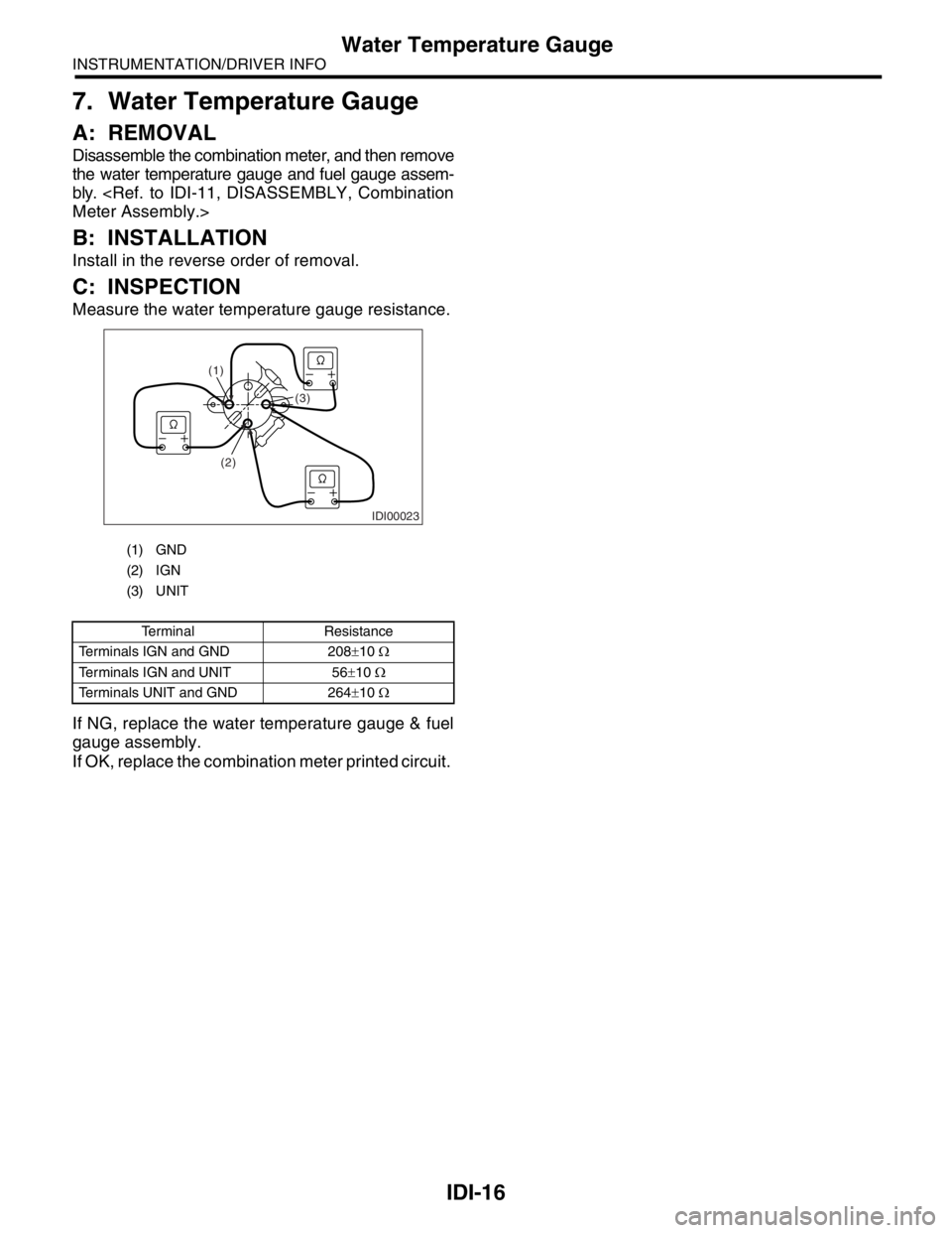
Measure the water temperature gauge resistance.
If NG, replace the water temperature gauge & fuel
gauge assembly.
If OK, replace the combination meter printed circuit.
(1) GND
(2) IGN
(3) UNIT
Terminal Resistance
Terminals IGN and GND 208±10 Ω
Terminals IGN and UNIT 56±10 Ω
Terminals UNIT and GND 264±10 Ω
IDI00023
(1)
(2)(3)