replace SUBARU FORESTER 2004 Service Service Manual
[x] Cancel search | Manufacturer: SUBARU, Model Year: 2004, Model line: FORESTER, Model: SUBARU FORESTER 2004Pages: 2870, PDF Size: 38.67 MB
Page 121 of 2870
AB-21
AIRBAG SYSTEM
Front Sub Sensor
10.Front Sub Sensor
A: REMOVAL
1) Turn the ignition switch to OFF.
2) Disconnect the ground cable from battery, and
wait for at least 20 seconds before starting work.
3) Remove the front grille and front grille side.
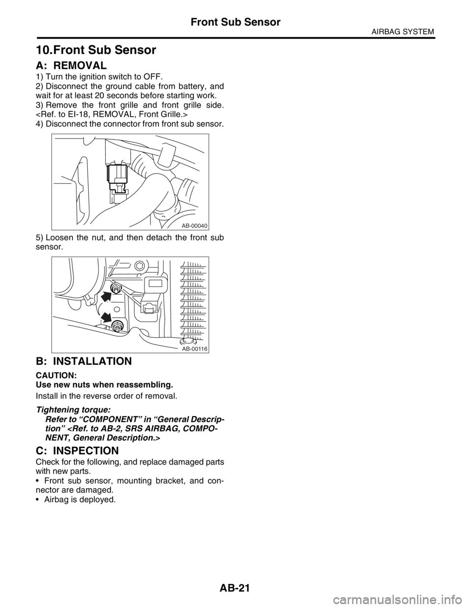
4) Disconnect the connector from front sub sensor.
5) Loosen the nut, and then detach the front sub
sensor.
B: INSTALLATION
CAUTION:
Use new nuts when reassembling.
Install in the reverse order of removal.
Tightening torque:
Refer to “COMPONENT” in “General Descrip-
tion”
C: INSPECTION
Check for the following, and replace damaged parts
with new parts.
Front sub sensor, mounting bracket, and con-
nector are damaged.
Airbag is deployed.
AB-00040
AB-00116
Page 131 of 2870
FUJI HEAVY INDUSTRIES LTD. G8080GE7
2004 FORESTER SERVICE MANUAL QUICK REFERENCE INDEX
BODY SECTION
This service manual has been prepared
to provide SUBARU service personnel
with the necessary information and data
for the correct maintenance and repair
of SUBARU vehicles.
This manual includes the procedures
for maintenance, disassembling, reas-
sembling, inspection and adjustment of
components and diagnostics for guid-
ance of experienced mechanics.
Please peruse and utilize this manual
fully to ensure complete repair work for
satisfying our customers by keeping
their vehicle in optimum condition.
When replacement of parts during
repair work is needed, be sure to use
SUBARU genuine parts.
All information, illustration and specifi-
cations contained in this manual are
based on the latest product information
available at the time of publication
approval.HVAC SYSTEM
(HEATER, VENTILATOR AND A/C)AC
HVAC SYSTEM (AUTO A/C)
(DIAGNOSTIC)AC
AIRBAG SYSTEM AB
AIRBAG SYSTEM (DIAGNOSTIC) AB
SEAT BELT SYSTEM SB
LIGHTING SYSTEM LI
WIPER AND WASHER SYSTEM WW
ENTERTAINMENT ET
COMMUNICATION SYSTEM COM
GLASS/WINDOW/MIRROR GW
BODY STRUCTURE BS
INSTRUMENTATION/DRIVER INFO IDI
SEAT SE
SECURITY AND LOCK SL
SUNROOF/T-TOP/CONVERTIBLE TOP
(SUNROOF)SR
EXTERIOR/INTERIOR TRIM EI
EXTERIOR BODY PANEL EB
Page 134 of 2870
AB-2
AIRBAG SYSTEM (DIAGNOSTIC)
Basic Diagnostic Procedure
1. Basic Diagnostic Procedure
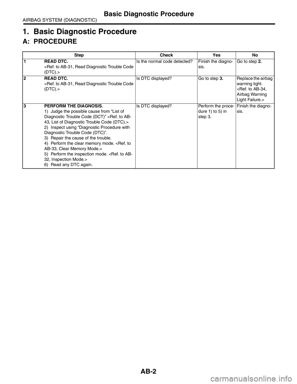
A: PROCEDURE
Step Check Yes No
1 READ DTC.
sis.Go to step 2.
2 READ DTC.
warning light.
Light Failure.>
3 PERFORM THE DIAGNOSIS.
1) Judge the possible cause from “List of
Diagnostic Trouble Code (DCT)”
2) Inspect using “Diagnostic Procedure with
Diagnostic Trouble Code (DTC)”.
3) Repair the cause of the trouble.
4) Perform the clear memory mode.
5) Perform the inspection mode.
6) Read any DTC again.Is DTC displayed? Perform the proce-
dure 1) to 5) in
step 3.Finish the diagno-
sis.
Page 136 of 2870
AB-4
AIRBAG SYSTEM (DIAGNOSTIC)
General Description
3. General Description
A: CAUTION
When servicing a vehicle, be sure to turn the ig-
nition switch to OFF, disconnect the ground cable
from battery, and wait for more than 20 seconds
before starting work.
The airbag system is fitted with a backup power
source. If the airbag system is serviced within 20
seconds after the ground cable is disconnected, it
may inflate.
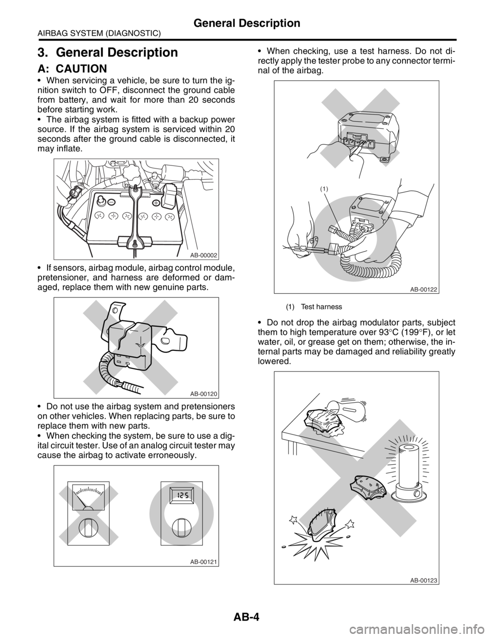
If sensors, airbag module, airbag control module,
pretensioner, and harness are deformed or dam-
aged, replace them with new genuine parts.
Do not use the airbag system and pretensioners
on other vehicles. When replacing parts, be sure to
replace them with new parts.
When checking the system, be sure to use a dig-
ital circuit tester. Use of an analog circuit tester may
cause the airbag to activate erroneously. When checking, use a test harness. Do not di-
rectly apply the tester probe to any connector termi-
nal of the airbag.
Do not drop the airbag modulator parts, subject
them to high temperature over 93°C (199°F), or let
water, oil, or grease get on them; otherwise, the in-
ternal parts may be damaged and reliability greatly
lowered.
AB-00002
AB-00120
AB-00121
(1) Test harness
AB-00122
(1)
AB-00123
Page 137 of 2870
AB-5
AIRBAG SYSTEM (DIAGNOSTIC)
General Description
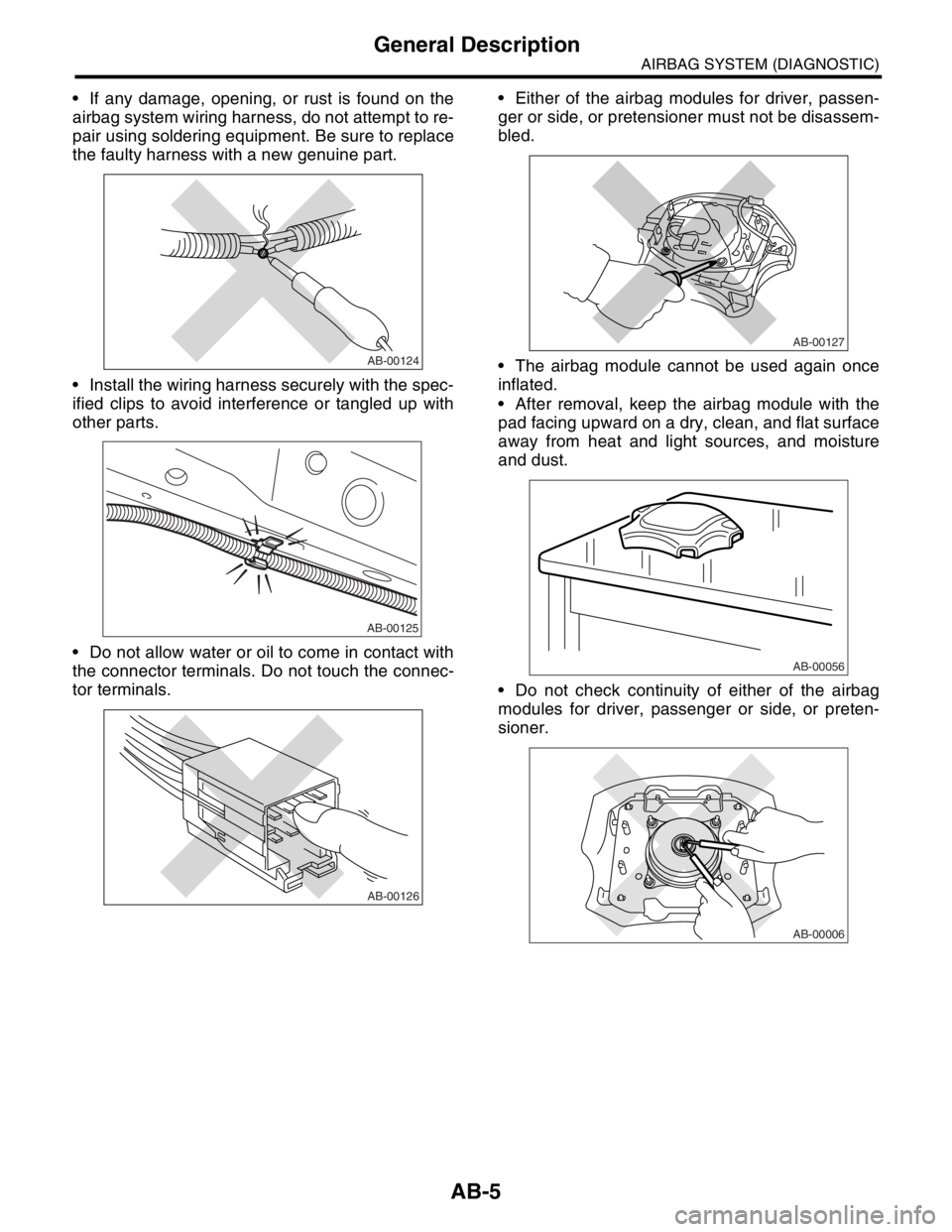
If any damage, opening, or rust is found on the
airbag system wiring harness, do not attempt to re-
pair using soldering equipment. Be sure to replace
the faulty harness with a new genuine part.
Install the wiring harness securely with the spec-
ified clips to avoid interference or tangled up with
other parts.
Do not allow water or oil to come in contact with
the connector terminals. Do not touch the connec-
tor terminals. Either of the airbag modules for driver, passen-
ger or side, or pretensioner must not be disassem-
bled.
The airbag module cannot be used again once
inflated.
After removal, keep the airbag module with the
pad facing upward on a dry, clean, and flat surface
away from heat and light sources, and moisture
and dust.
Do not check continuity of either of the airbag
modules for driver, passenger or side, or preten-
sioner.
AB-00124
AB-00125
AB-00126
AB-00127
AB-00056
AB-00006
Page 150 of 2870

AB-18
AIRBAG SYSTEM (DIAGNOSTIC)
General Description
AIRBAG RESISTOR
ILLUSTRATION TOOL NUMBER DESCRIPTION REMARKS
98299PA040 AIRBAG RESISTOR Used in replacement of airbag module which
resistance value is same as airbag module.
ST98299PA040
AB-00433
3
1 2
1
2 1
2 1
3 4 5 6 24 3
Page 167 of 2870
AB-35
AIRBAG SYSTEM (DIAGNOSTIC)
Airbag Warning Light Failure
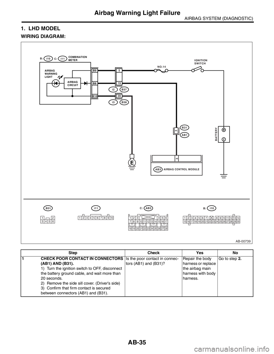
1. LHD MODEL
WIRING DIAGRAM:
Step Check Yes No
1 CHECK POOR CONTACT IN CONNECTORS
(AB1) AND (B31).
1) Turn the ignition switch to OFF, disconnect
the battery ground cable, and wait more than
20 seconds.
2) Remove the side sill cover. (Driver’s side)
3) Confirm that firm contact is secured
between connectors (AB1) and (B31).Is the poor contact in connec-
tors (AB1) and (B31)?Repair the body
harness or replace
the airbag main
harness with body
harness.Go to step 2.
AB-00739
12
34561
2345678910123456789101112131415161718192021222324252627282930
B31 i11AB3
i10
B:
C: i10
i11
AIRBAG
WARNING
LIGHTCOMBINATION
METERB9
B8
B10
NO.14
i3B38 28
i2B37 19
5
AIRBAG CONTROL MODULEAB3
B31
AB1
3
3
AIRBAG
CIRCUIT
E
BATTERY
1234567891011121314151617
1819202122232425262728
IGNITION
SWITCH
B: C:
Page 168 of 2870
AB-36
AIRBAG SYSTEM (DIAGNOSTIC)
Airbag Warning Light Failure
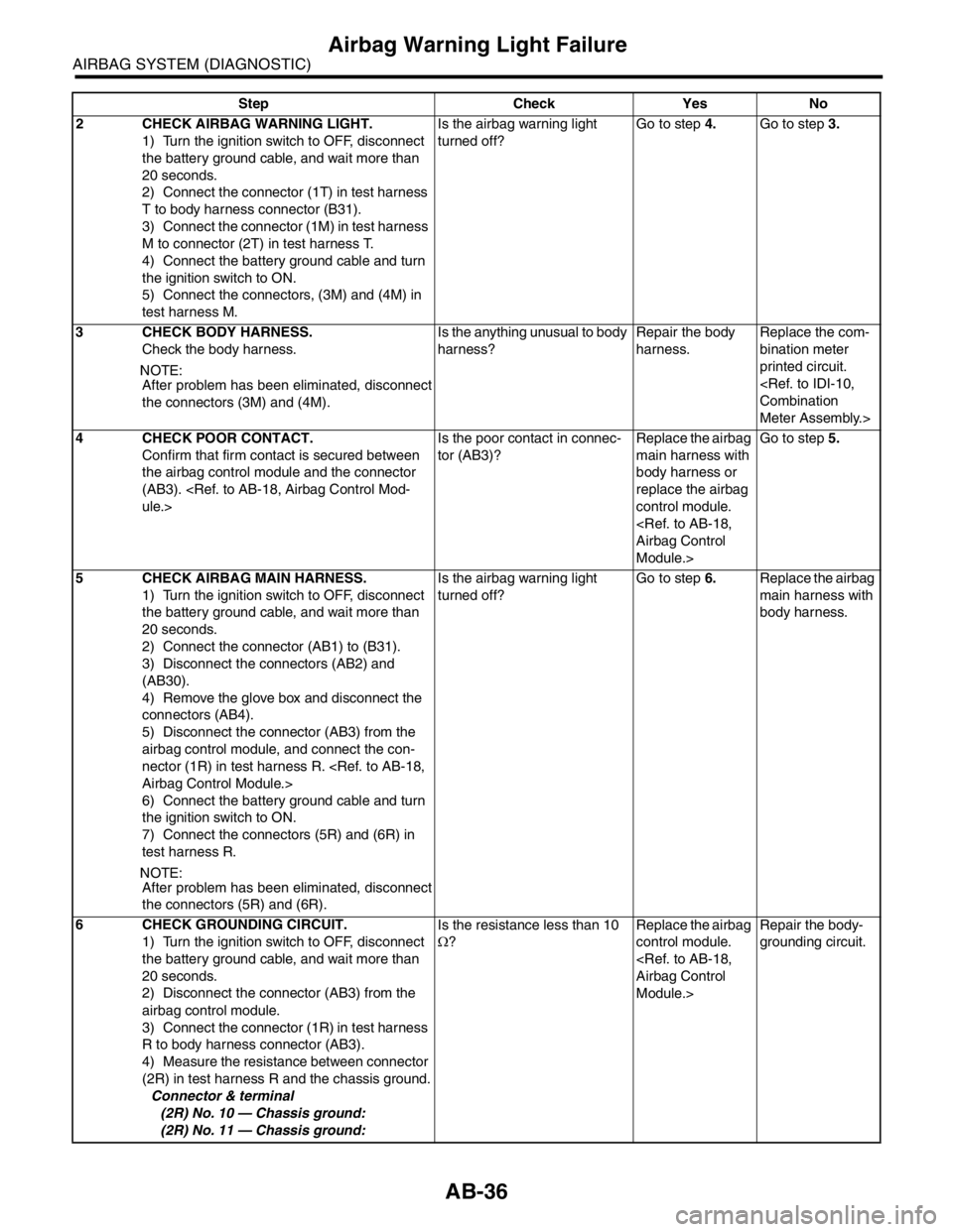
2 CHECK AIRBAG WARNING LIGHT.
1) Turn the ignition switch to OFF, disconnect
the battery ground cable, and wait more than
20 seconds.
2) Connect the connector (1T) in test harness
T to body harness connector (B31).
3) Connect the connector (1M) in test harness
M to connector (2T) in test harness T.
4) Connect the battery ground cable and turn
the ignition switch to ON.
5) Connect the connectors, (3M) and (4M) in
test harness M.Is the airbag warning light
turned off?Go to step 4.Go to step 3.
3 CHECK BODY HARNESS.
Check the body harness.
N
OTE:
After problem has been eliminated, disconnect
the connectors (3M) and (4M).Is the anything unusual to body
harness? Repair the body
harness.Replace the com-
bination meter
printed circuit.
Meter Assembly.>
4 CHECK POOR CONTACT.
Confirm that firm contact is secured between
the airbag control module and the connector
(AB3).
tor (AB3)?Replace the airbag
main harness with
body harness or
replace the airbag
control module.
Module.>Go to step 5.
5 CHECK AIRBAG MAIN HARNESS.
1) Turn the ignition switch to OFF, disconnect
the battery ground cable, and wait more than
20 seconds.
2) Connect the connector (AB1) to (B31).
3) Disconnect the connectors (AB2) and
(AB30).
4) Remove the glove box and disconnect the
connectors (AB4).
5) Disconnect the connector (AB3) from the
airbag control module, and connect the con-
nector (1R) in test harness R.
6) Connect the battery ground cable and turn
the ignition switch to ON.
7) Connect the connectors (5R) and (6R) in
test harness R.
N
OTE:
After problem has been eliminated, disconnect
the connectors (5R) and (6R).Is the airbag warning light
turned off?Go to step 6.Replace the airbag
main harness with
body harness.
6 CHECK GROUNDING CIRCUIT.
1) Turn the ignition switch to OFF, disconnect
the battery ground cable, and wait more than
20 seconds.
2) Disconnect the connector (AB3) from the
airbag control module.
3) Connect the connector (1R) in test harness
R to body harness connector (AB3).
4) Measure the resistance between connector
(2R) in test harness R and the chassis ground.
Connector & terminal
(2R) No. 10 — Chassis ground:
(2R) No. 11 — Chassis ground: Is the resistance less than 10
Ω?Replace the airbag
control module.
Module.>Repair the body-
grounding circuit. Step Check Yes No
Page 169 of 2870
AB-37
AIRBAG SYSTEM (DIAGNOSTIC)
Airbag Warning Light Failure
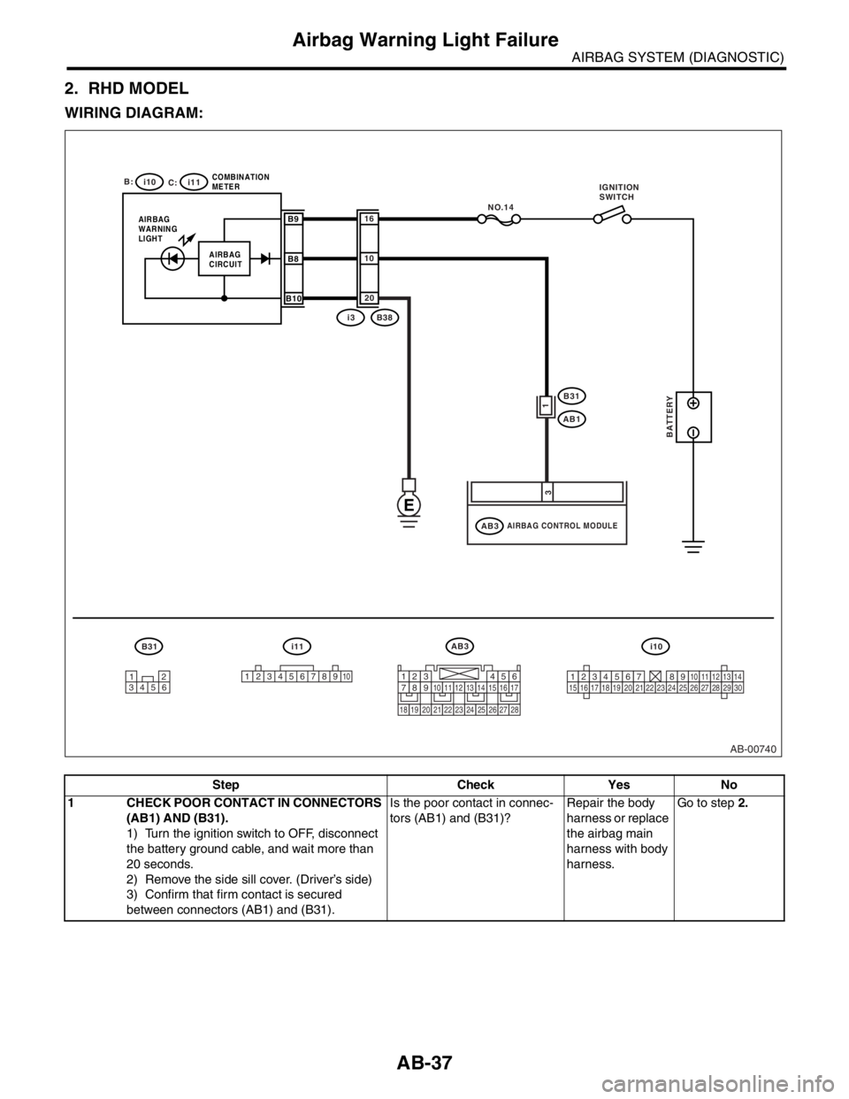
2. RHD MODEL
WIRING DIAGRAM:
Step Check Yes No
1 CHECK POOR CONTACT IN CONNECTORS
(AB1) AND (B31).
1) Turn the ignition switch to OFF, disconnect
the battery ground cable, and wait more than
20 seconds.
2) Remove the side sill cover. (Driver’s side)
3) Confirm that firm contact is secured
between connectors (AB1) and (B31).Is the poor contact in connec-
tors (AB1) and (B31)?Repair the body
harness or replace
the airbag main
harness with body
harness.Go to step 2.
AB-00740
12
34561
2345678910123456789101112131415161718192021222324252627282930
B31 i11AB3
i10
B:
C: i10
i11
AIRBAG
WARNING
LIGHTCOMBINATION
METERB9
B8
B10
NO.14
i3B38 20
10
16
AIRBAG CONTROL MODULEAB3
B31
AB1
1
3
AIRBAG
CIRCUIT
E
BATTERY
1234567891011121314151617
1819202122232425262728
IGNITION
SWITCH
Page 170 of 2870
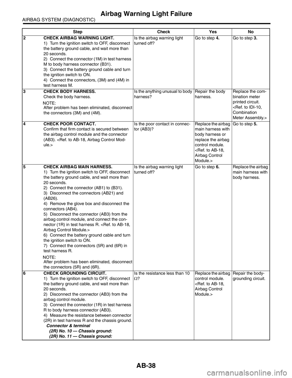
AB-38
AIRBAG SYSTEM (DIAGNOSTIC)
Airbag Warning Light Failure
2 CHECK AIRBAG WARNING LIGHT.
1) Turn the ignition switch to OFF, disconnect
the battery ground cable, and wait more than
20 seconds.
2) Connect the connector (1M) in test harness
M to body harness connector (B31).
3) Connect the battery ground cable and turn
the ignition switch to ON.
4) Connect the connectors, (3M) and (4M) in
test harness M.Is the airbag warning light
turned off?Go to step 4.Go to step 3.
3 CHECK BODY HARNESS.
Check the body harness.
N
OTE:
After problem has been eliminated, disconnect
the connectors (3M) and (4M).Is the anything unusual to body
harness?Repair the body
harness.Replace the com-
bination meter
printed circuit.
Meter Assembly.>
4 CHECK POOR CONTACT.
Confirm that firm contact is secured between
the airbag control module and the connector
(AB3).
tor (AB3)? Replace the airbag
main harness with
body harness or
replace the airbag
control module.
Module.>Go to step 5.
5 CHECK AIRBAG MAIN HARNESS.
1) Turn the ignition switch to OFF, disconnect
the battery ground cable, and wait more than
20 seconds.
2) Connect the connector (AB1) to (B31).
3) Disconnect the connectors (AB21) and
(AB26).
4) Remove the glove box and disconnect the
connectors (AB4).
5) Disconnect the connector (AB3) from the
airbag control module, and connect the con-
nector (1R) in test harness R.
6) Connect the battery ground cable and turn
the ignition switch to ON.
7) Connect the connectors (5R) and (6R) in
test harness R.
N
OTE:
After problem has been eliminated, disconnect
the connectors (5R) and (6R).Is the airbag warning light
turned off? Go to step 6.Replace the airbag
main harness with
body harness.
6 CHECK GROUNDING CIRCUIT.
1) Turn the ignition switch to OFF, disconnect
the battery ground cable, and wait more than
20 seconds.
2) Disconnect the connector (AB3) from the
airbag control module.
3) Connect the connector (1R) in test harness
R to body harness connector (AB3).
4) Measure the resistance between connector
(2R) in test harness R and the chassis ground.
Connector & terminal
(2R) No. 10 — Chassis ground:
(2R) No. 11 — Chassis ground: Is the resistance less than 10
Ω?Replace the airbag
control module.
Module.>Repair the body-
grounding circuit. Step Check Yes No