driver SUBARU FORESTER 2004 Service Manual PDF
[x] Cancel search | Manufacturer: SUBARU, Model Year: 2004, Model line: FORESTER, Model: SUBARU FORESTER 2004Pages: 2870, PDF Size: 38.67 MB
Page 253 of 2870
FUJI HEAVY INDUSTRIES LTD. G8080GE7
2004 FORESTER SERVICE MANUAL QUICK REFERENCE INDEX
BODY SECTION
This service manual has been prepared
to provide SUBARU service personnel
with the necessary information and data
for the correct maintenance and repair
of SUBARU vehicles.
This manual includes the procedures
for maintenance, disassembling, reas-
sembling, inspection and adjustment of
components and diagnostics for guid-
ance of experienced mechanics.
Please peruse and utilize this manual
fully to ensure complete repair work for
satisfying our customers by keeping
their vehicle in optimum condition.
When replacement of parts during
repair work is needed, be sure to use
SUBARU genuine parts.
All information, illustration and specifi-
cations contained in this manual are
based on the latest product information
available at the time of publication
approval.HVAC SYSTEM
(HEATER, VENTILATOR AND A/C)AC
HVAC SYSTEM (AUTO A/C)
(DIAGNOSTIC)AC
AIRBAG SYSTEM AB
AIRBAG SYSTEM (DIAGNOSTIC) AB
SEAT BELT SYSTEM SB
LIGHTING SYSTEM LI
WIPER AND WASHER SYSTEM WW
ENTERTAINMENT ET
COMMUNICATION SYSTEM COM
GLASS/WINDOW/MIRROR GW
BODY STRUCTURE BS
INSTRUMENTATION/DRIVER INFO IDI
SEAT SE
SECURITY AND LOCK SL
SUNROOF/T-TOP/CONVERTIBLE TOP
(SUNROOF)SR
EXTERIOR/INTERIOR TRIM EI
EXTERIOR BODY PANEL EB
Page 268 of 2870
LI-14
LIGHTING SYSTEM
Headlight Assembly
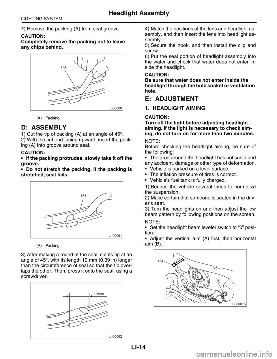
7) Remove the packing (A) from seal groove.
CAUTION:
Completely remove the packing not to leave
any chips behind.
D: ASSEMBLY
1) Cut the tip of packing (A) at an angle of 45°.
2) With the cut end facing upward, insert the pack-
ing (A) into groove around seal.
CAUTION:
If the packing protrudes, slowly take it off the
groove.
Do not stretch the packing. If the packing is
stretched, seal fails.
3) After making a round of the seal, cut its tip at an
angle of 45°, with its length 10 mm (0.39 in) longer
than the circumference of seal so that the tip over-
laps the other. Then, press it onto the seal, using a
screwdriver.4) Match the positions of the lens and headlight as-
sembly, and then insert the lens into headlight as-
sembly.
5) Secure the hook, and then install the clip and
screw.
6) Put the seal portion of headlight assembly into
the water and check that water does not enter in-
side the headlight.
CAUTION:
Be sure that water does not enter inside the
headlight through the bulb socket or ventilation
hole.
E: ADJUSTMENT
1. HEADLIGHT AIMING
CAUTION:
Turn off the light before adjusting headlight
aiming. If the light is necessary to check aim-
ing, do not turn on for more than two minutes.
NOTE:
Before checking the headlight aiming, be sure of
the following:
The area around the headlight has not sustained
any accident, damage or other type of deformation.
Vehicle is parked on a level surface.
The inflation pressure of tires is correct.
Vehicle’s fuel tank is fully charged.
1) Bounce the vehicle several times to normalize
the suspension.
2) Make certain that someone is seated in the driv-
er’s seat.
3) Turn the headlights on and then adjust the low
beam pattern by following positions on the screen.
NOTE:
Set the headlight beam leveler switch to “0” posi-
tion.
Adjust the vertical aim (A) first, then horizontal
aim (B).(A) Packing
(A) Packing
LI-00060
(A)
LI-00061
(A)
LI-00062
10mm
LI-00015
(A)
(B)
Page 279 of 2870
LI-25
LIGHTING SYSTEM
Rear Fog Light Bulb
21.Rear Fog Light Bulb
A: REMOVAL
NOTE:
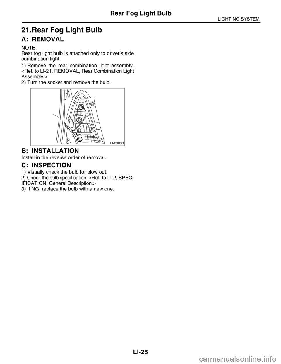
Rear fog light bulb is attached only to driver’s side
combination light.
1) Remove the rear combination light assembly.
2) Turn the socket and remove the bulb.
B: INSTALLATION
Install in the reverse order of removal.
C: INSPECTION
1) Visually check the bulb for blow out.
2) Check the bulb specification.
3) If NG, replace the bulb with a new one.
LI-00033
Page 281 of 2870
LI-27
LIGHTING SYSTEM
High-mounted Stop Light
23.High-mounted Stop Light
A: REMOVAL
1) Disconnect the ground cable from battery.
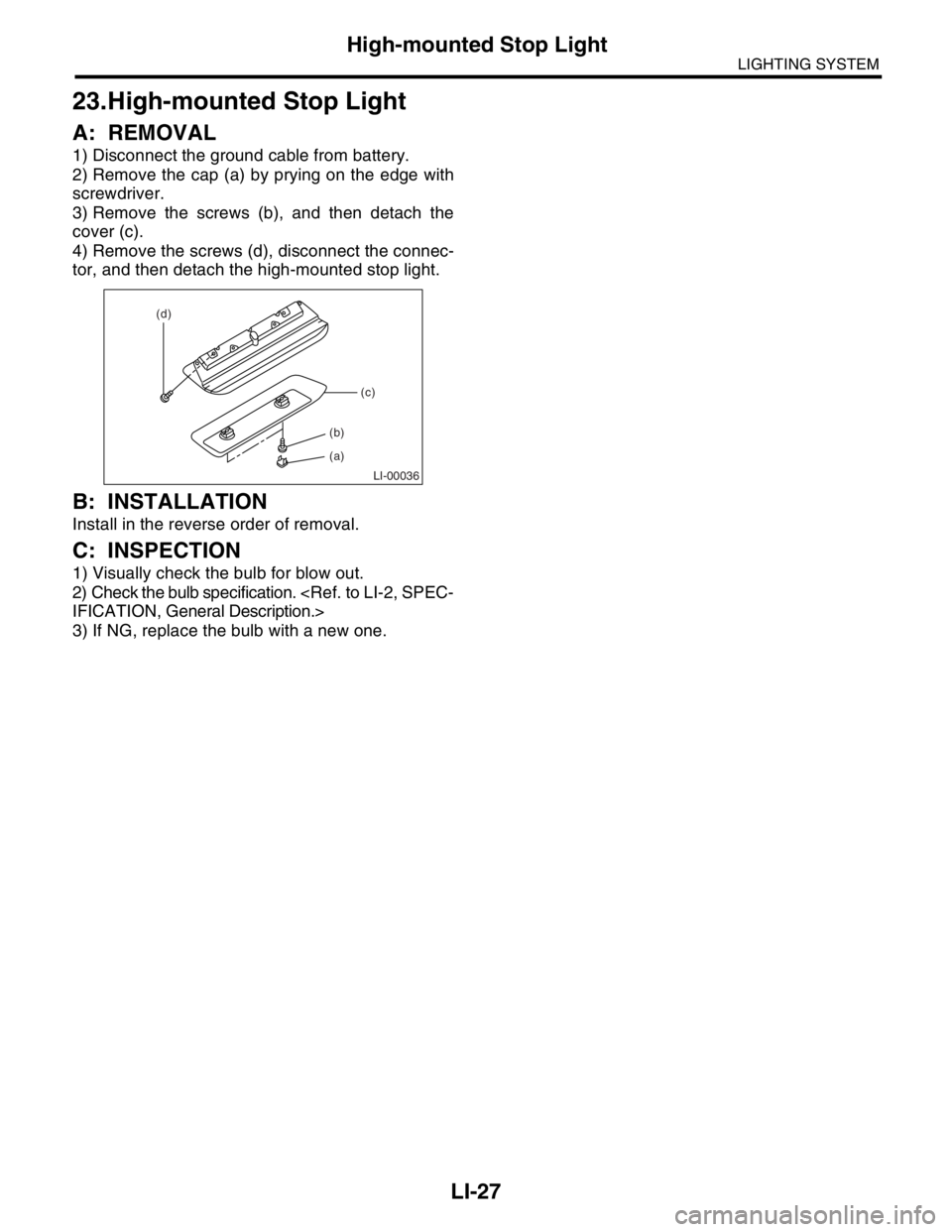
2) Remove the cap (a) by prying on the edge with
screwdriver.
3) Remove the screws (b), and then detach the
cover (c).
4) Remove the screws (d), disconnect the connec-
tor, and then detach the high-mounted stop light.
B: INSTALLATION
Install in the reverse order of removal.
C: INSPECTION
1) Visually check the bulb for blow out.
2) Check the bulb specification.
3) If NG, replace the bulb with a new one.
LI-00036
(d)
(c)
(a) (b)
Page 283 of 2870
LI-29
LIGHTING SYSTEM
Spot Map Light
25.Spot Map Light
A: REMOVAL
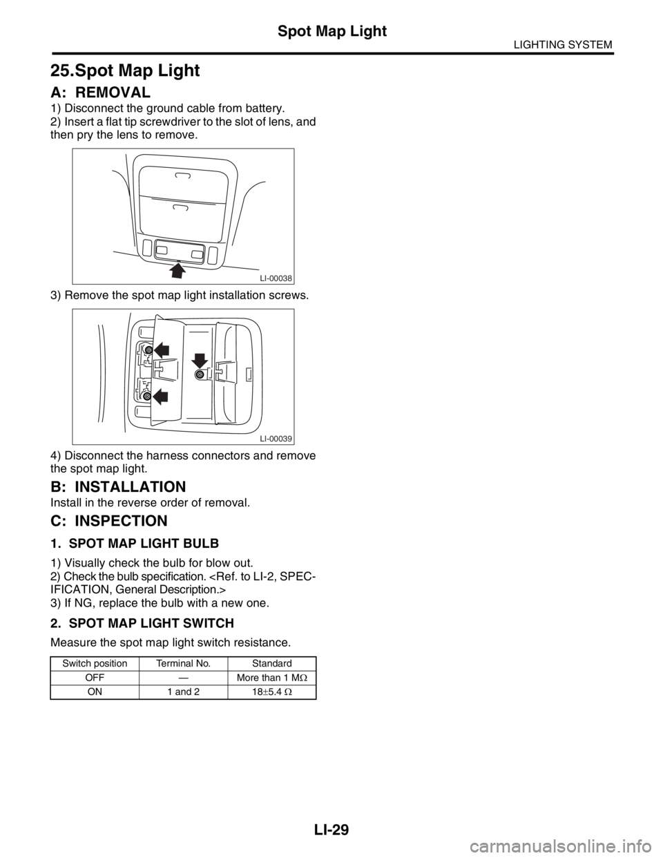
1) Disconnect the ground cable from battery.
2) Insert a flat tip screwdriver to the slot of lens, and
then pry the lens to remove.
3) Remove the spot map light installation screws.
4) Disconnect the harness connectors and remove
the spot map light.
B: INSTALLATION
Install in the reverse order of removal.
C: INSPECTION
1. SPOT MAP LIGHT BULB
1) Visually check the bulb for blow out.
2) Check the bulb specification.
3) If NG, replace the bulb with a new one.
2. SPOT MAP LIGHT SWITCH
Measure the spot map light switch resistance.
Switch position Terminal No. Standard
OFF — More than 1 MΩ
ON 1 and 2 18±5.4 Ω
LI-00038
LI-00039
Page 287 of 2870
FUJI HEAVY INDUSTRIES LTD. G8080GE7
2004 FORESTER SERVICE MANUAL QUICK REFERENCE INDEX
BODY SECTION
This service manual has been prepared
to provide SUBARU service personnel
with the necessary information and data
for the correct maintenance and repair
of SUBARU vehicles.
This manual includes the procedures
for maintenance, disassembling, reas-
sembling, inspection and adjustment of
components and diagnostics for guid-
ance of experienced mechanics.
Please peruse and utilize this manual
fully to ensure complete repair work for
satisfying our customers by keeping
their vehicle in optimum condition.
When replacement of parts during
repair work is needed, be sure to use
SUBARU genuine parts.
All information, illustration and specifi-
cations contained in this manual are
based on the latest product information
available at the time of publication
approval.HVAC SYSTEM
(HEATER, VENTILATOR AND A/C)AC
HVAC SYSTEM (AUTO A/C)
(DIAGNOSTIC)AC
AIRBAG SYSTEM AB
AIRBAG SYSTEM (DIAGNOSTIC) AB
SEAT BELT SYSTEM SB
LIGHTING SYSTEM LI
WIPER AND WASHER SYSTEM WW
ENTERTAINMENT ET
COMMUNICATION SYSTEM COM
GLASS/WINDOW/MIRROR GW
BODY STRUCTURE BS
INSTRUMENTATION/DRIVER INFO IDI
SEAT SE
SECURITY AND LOCK SL
SUNROOF/T-TOP/CONVERTIBLE TOP
(SUNROOF)SR
EXTERIOR/INTERIOR TRIM EI
EXTERIOR BODY PANEL EB
Page 303 of 2870

WW-15
WIPER AND WASHER SYSTEM
Front Washer Nozzle
8. Front Washer Nozzle
A: REMOVAL
1) Remove the washer hose from the washer noz-
zle.
2) Open the clips on the underside of the hood with
a thin screwdriver or other tool, and remove the
washer nozzle.
B: INSTALLATION
1) Install in the reverse order of removal.
NOTE:
Hoses have rib as eyemark for twist-proof.
2) Adjust the position of the washer liquid sprayer.
C: INSPECTION
Make sure the nozzle and hose are not clogged.
Check hoses for twist or fold.
D: ADJUSTMENT
NOTE:
It is not necessary to adjust the washer injection
position because of spreading nozzle type.
WW-00023
Page 306 of 2870

WW-18
WIPER AND WASHER SYSTEM
Rear Washer
11.Rear Washer
A: REMOVAL
1) Remove the rear gate upper trim.
2) Remove the washer hose from the washer noz-
zle.
3) Push the anchor portion of washer nozzle with a
thin screwdriver or other tool, and remove the
washer nozzle.
B: INSTALLATION
1) Install in the reverse order of removal.
2) Adjust the position of the washer liquid sprayer.
C: INSPECTION
Make sure the nozzle and hose are not clogged.
Check hoses for twist or fold.
D: ADJUSTMENT
1) Turn the wiper switch to OFF position.
2) When the vehicle stops, adjust the washer injec-
tion position as shown in the figure.
Injection position:
A: 35 mm (1.38 in)
B: 72
°
(1) Nozzle
WW-00201
WW-00054
A (1)
B
Page 309 of 2870
FUJI HEAVY INDUSTRIES LTD. G8080GE7
2004 FORESTER SERVICE MANUAL QUICK REFERENCE INDEX
BODY SECTION
This service manual has been prepared
to provide SUBARU service personnel
with the necessary information and data
for the correct maintenance and repair
of SUBARU vehicles.
This manual includes the procedures
for maintenance, disassembling, reas-
sembling, inspection and adjustment of
components and diagnostics for guid-
ance of experienced mechanics.
Please peruse and utilize this manual
fully to ensure complete repair work for
satisfying our customers by keeping
their vehicle in optimum condition.
When replacement of parts during
repair work is needed, be sure to use
SUBARU genuine parts.
All information, illustration and specifi-
cations contained in this manual are
based on the latest product information
available at the time of publication
approval.HVAC SYSTEM
(HEATER, VENTILATOR AND A/C)AC
HVAC SYSTEM (AUTO A/C)
(DIAGNOSTIC)AC
AIRBAG SYSTEM AB
AIRBAG SYSTEM (DIAGNOSTIC) AB
SEAT BELT SYSTEM SB
LIGHTING SYSTEM LI
WIPER AND WASHER SYSTEM WW
ENTERTAINMENT ET
COMMUNICATION SYSTEM COM
GLASS/WINDOW/MIRROR GW
BODY STRUCTURE BS
INSTRUMENTATION/DRIVER INFO IDI
SEAT SE
SECURITY AND LOCK SL
SUNROOF/T-TOP/CONVERTIBLE TOP
(SUNROOF)SR
EXTERIOR/INTERIOR TRIM EI
EXTERIOR BODY PANEL EB
Page 315 of 2870
ET-5
ENTERTAINMENT
Radio Body
4. Radio Body
A: REMOVAL
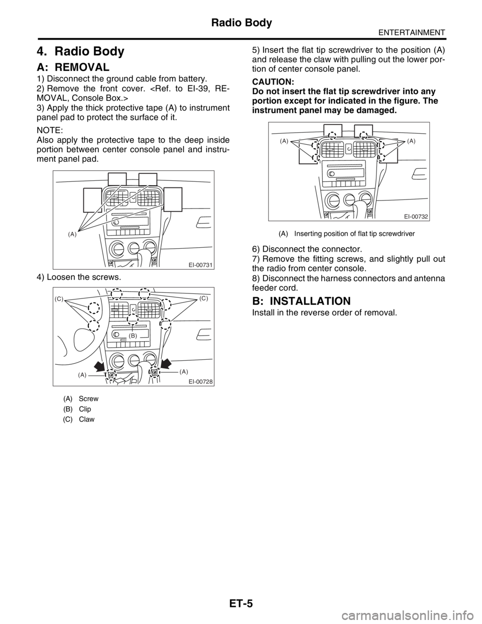
1) Disconnect the ground cable from battery.
2) Remove the front cover.
3) Apply the thick protective tape (A) to instrument
panel pad to protect the surface of it.
NOTE:
Also apply the protective tape to the deep inside
portion between center console panel and instru-
ment panel pad.
4) Loosen the screws.5) Insert the flat tip screwdriver to the position (A)
and release the claw with pulling out the lower por-
tion of center console panel.
CAUTION:
Do not insert the flat tip screwdriver into any
portion except for indicated in the figure. The
instrument panel may be damaged.
6) Disconnect the connector.
7) Remove the fitting screws, and slightly pull out
the radio from center console.
8) Disconnect the harness connectors and antenna
feeder cord.
B: INSTALLATION
Install in the reverse order of removal.
(A) Screw
(B) Clip
(C) Claw
EI-00731
(A)
EI-00728
(C)
(A)(A)(C)
(B)
(A) Inserting position of flat tip screwdriver
EI-00732
(A) (A)