SUBARU LEGACY 1999 Service Repair Manual
LEGACY 1999
SUBARU
SUBARU
https://www.carmanualsonline.info/img/17/57435/w960_57435-0.png
SUBARU LEGACY 1999 Service Repair Manual
Trending: brake rotor, reset, heating, coolant, wheel size, Engine cooling, keyless entry
Page 141 of 1456
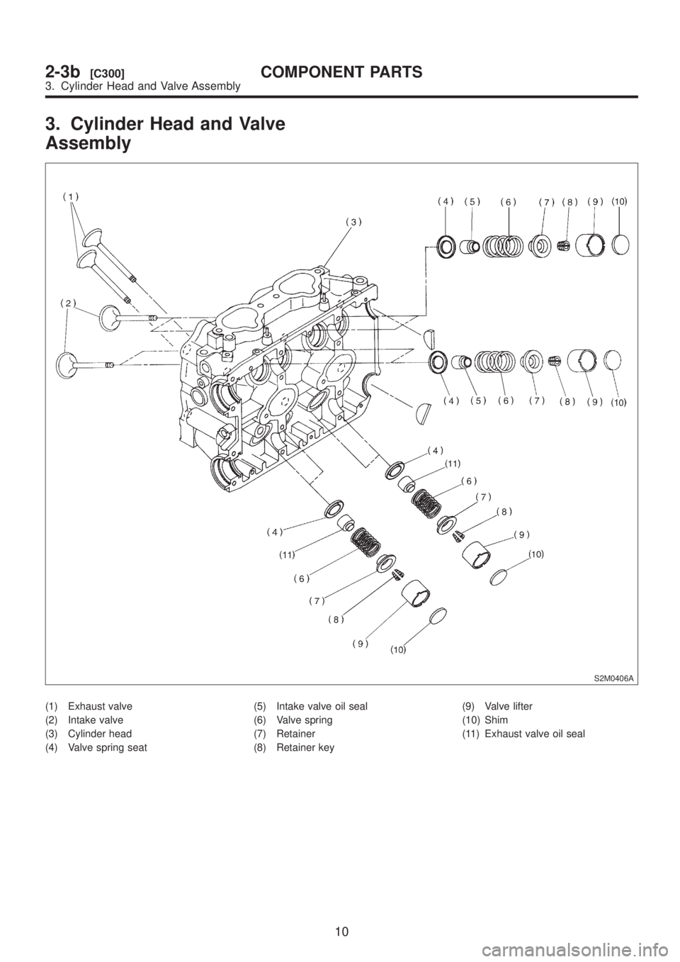
3. Cylinder Head and Valve
Assembly
S2M0406A
(1) Exhaust valve
(2) Intake valve
(3) Cylinder head
(4) Valve spring seat(5) Intake valve oil seal
(6) Valve spring
(7) Retainer
(8) Retainer key(9) Valve lifter
(10) Shim
(11) Exhaust valve oil seal
10
2-3b[C300]COMPONENT PARTS
3. Cylinder Head and Valve Assembly
Page 142 of 1456
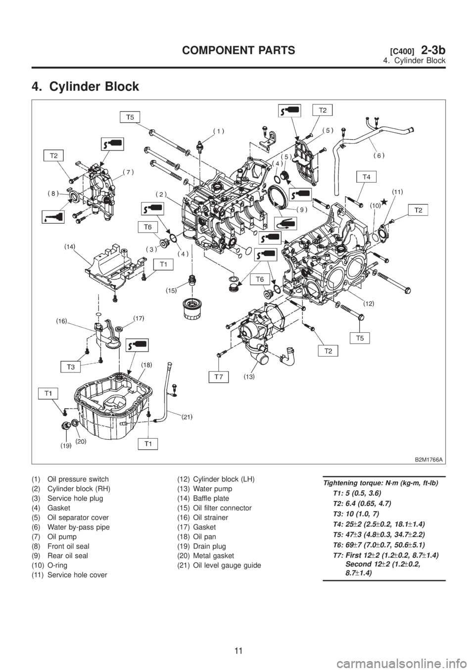
4. Cylinder Block
B2M1766A
(1) Oil pressure switch
(2) Cylinder block (RH)
(3) Service hole plug
(4) Gasket
(5) Oil separator cover
(6) Water by-pass pipe
(7) Oil pump
(8) Front oil seal
(9) Rear oil seal
(10) O-ring
(11) Service hole cover(12) Cylinder block (LH)
(13) Water pump
(14) Baffle plate
(15) Oil filter connector
(16) Oil strainer
(17) Gasket
(18) Oil pan
(19) Drain plug
(20) Metal gasket
(21) Oil level gauge guideTightening torque: N´m (kg-m, ft-lb)
T1:
5 (0.5, 3.6)
T2:6.4 (0.65, 4.7)
T3:10 (1.0, 7)
T4:25±2 (2.5±0.2, 18.1±1.4)
T5:47±3 (4.8±0.3, 34.7±2.2)
T6:69±7 (7.0±0.7, 50.6±5.1)
T7:First 12±2 (1.2±0.2, 8.7±1.4)
Second 12
±2 (1.2±0.2,
8.7
±1.4)
11
[C400]2-3bCOMPONENT PARTS
4. Cylinder Block
Page 143 of 1456
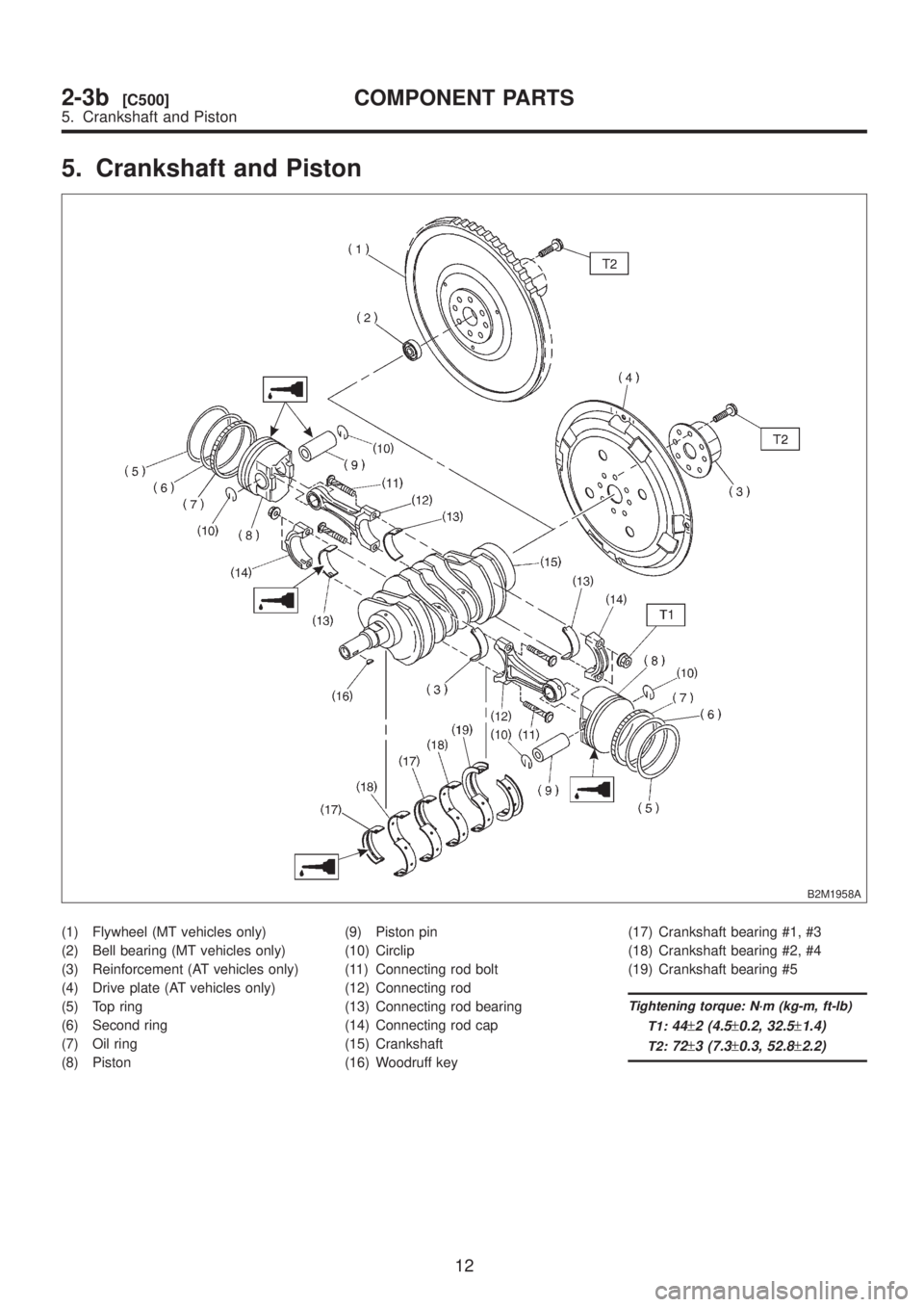
5. Crankshaft and Piston
B2M1958A
(1) Flywheel (MT vehicles only)
(2) Bell bearing (MT vehicles only)
(3) Reinforcement (AT vehicles only)
(4) Drive plate (AT vehicles only)
(5) Top ring
(6) Second ring
(7) Oil ring
(8) Piston(9) Piston pin
(10) Circlip
(11) Connecting rod bolt
(12) Connecting rod
(13) Connecting rod bearing
(14) Connecting rod cap
(15) Crankshaft
(16) Woodruff key(17) Crankshaft bearing #1, #3
(18) Crankshaft bearing #2, #4
(19) Crankshaft bearing #5
Tightening torque: N´m (kg-m, ft-lb)
T1:
44±2 (4.5±0.2, 32.5±1.4)
T2:72±3 (7.3±0.3, 52.8±2.2)
12
2-3b[C500]COMPONENT PARTS
5. Crankshaft and Piston
Page 144 of 1456
1. Precautions
A: GENERAL PRECAUTIONS
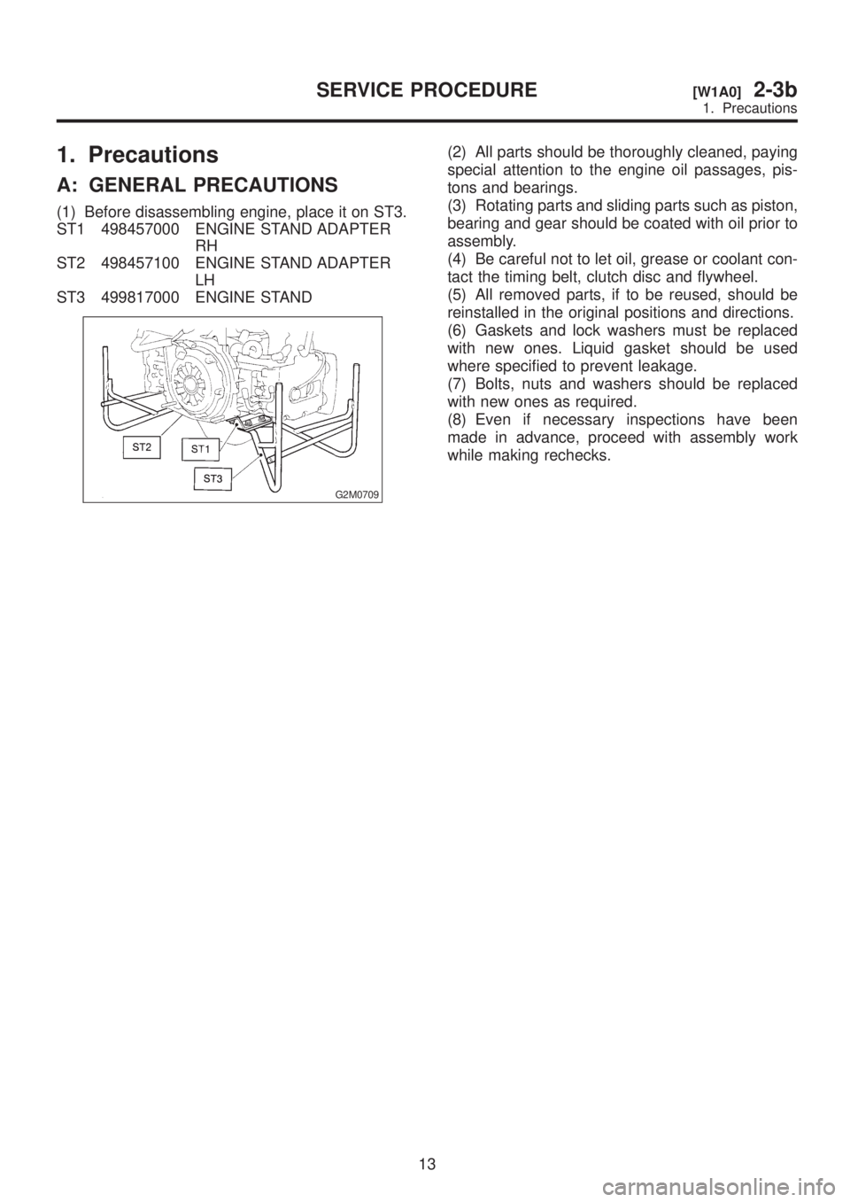
(1) Before disassembling engine, place it on ST3.
ST1 498457000 ENGINE STAND ADAPTER
RH
ST2 498457100 ENGINE STAND ADAPTER
LH
ST3 499817000 ENGINE STAND
G2M0709
(2) All parts should be thoroughly cleaned, paying
special attention to the engine oil passages, pis-
tons and bearings.
(3) Rotating parts and sliding parts such as piston,
bearing and gear should be coated with oil prior to
assembly.
(4) Be careful not to let oil, grease or coolant con-
tact the timing belt, clutch disc and flywheel.
(5) All removed parts, if to be reused, should be
reinstalled in the original positions and directions.
(6) Gaskets and lock washers must be replaced
with new ones. Liquid gasket should be used
where specified to prevent leakage.
(7) Bolts, nuts and washers should be replaced
with new ones as required.
(8) Even if necessary inspections have been
made in advance, proceed with assembly work
while making rechecks.
13
[W1A0]2-3bSERVICE PROCEDURE
1. Precautions
Page 145 of 1456
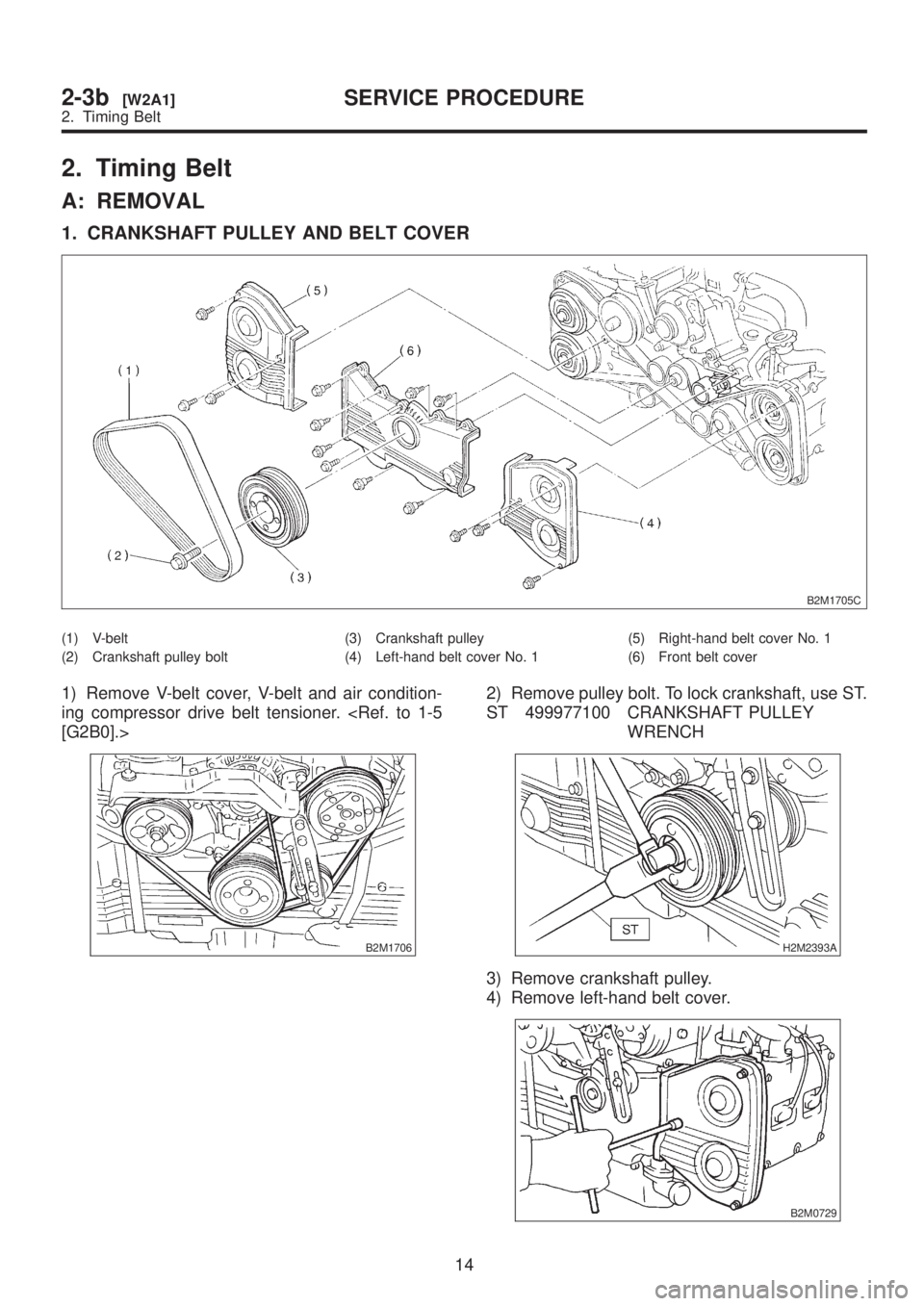
2. Timing Belt
A: REMOVAL
1. CRANKSHAFT PULLEY AND BELT COVER
B2M1705C
(1) V-belt
(2) Crankshaft pulley bolt(3) Crankshaft pulley
(4) Left-hand belt cover No. 1(5) Right-hand belt cover No. 1
(6) Front belt cover
1) Remove V-belt cover, V-belt and air condition-
ing compressor drive belt tensioner.
[G2B0].>
B2M1706
2) Remove pulley bolt. To lock crankshaft, use ST.
ST 499977100 CRANKSHAFT PULLEY
WRENCH
H2M2393A
3) Remove crankshaft pulley.
4) Remove left-hand belt cover.
B2M0729
14
2-3b[W2A1]SERVICE PROCEDURE
2. Timing Belt
Page 146 of 1456
5) Remove right-hand belt cover.
B2M0730
6) Remove front belt cover.
B2M0731
2. TIMING BELT
S2M0295A
(1) Timing belt guide (MT vehicles
only)(2) Belt idler
(3) Timing belt(a) Alignment marks
G2M0713
15
[W2A2]2-3bSERVICE PROCEDURE
2. Timing Belt
Page 147 of 1456
1) Remove timing belt guide. (MT vehicles only)
S2M0294
2) If alignment mark and/or arrow mark (which
indicates rotation direction) on timing belt fade
away, put new marks before removing timing belt
as follows:
(1) Turn crankshaft using ST, and align align-
ment marks on crankshaft sprocket, left-hand
intake camshaft sprocket, left-hand exhaust
camshaft sprocket, right-hand intake camshaft
sprocket and right hand exhaust camshaft
sprocket with notches of belt cover and cylinder
block.
ST 499987500 CRANKSHAFT SOCKET
S2M0407A
(2) Using white paint, put alignment and/or
arrow marks on timing belts in relation to the
sprockets.
Z1: 54.5 tooth length
Z
2: 51 tooth length
Z
3: 28 tooth length
H2M2396A
S2M0408
B2M0689
3) Remove belt idler.
H2M2398
16
2-3b[W2A2]SERVICE PROCEDURE
2. Timing Belt
Page 148 of 1456
4) Remove timing belt.
CAUTION:
After timing belt has been removed, never
rotate intake and exhaust, camshaft sprocket.
If camshaft sprocket is rotated, the intake and
exhaust valve heads strike together and valve
stems are bent.
S2M0409
3. BELT IDLER AND AUTOMATIC BELT TENSION ADJUSTER ASSEMBLY
H2M2400C
(1) Belt idler
(2) Belt idler No. 2(3) Automatic belt tension adjuster
ASSY
1) Remove belt idler.
S2M0410
2) Remove belt idler No. 2.
S2M0411
17
[W2A3]2-3bSERVICE PROCEDURE
2. Timing Belt
Page 149 of 1456
3) Remove automatic belt tension adjuster assem-
bly.
S2M0412
4. SPROCKET
H2M2404C
(1) Left-hand intake camshaft
sprocket
(2) Left-hand exhaust camshaft
sprocket(3) Right-hand intake camshaft
sprocket
(4) Right-hand exhaust camshaft
sprocket(5) Crankshaft sprocket
(6) Tensioner bracket
(7) Left-hand belt cover No. 2
(8) Right-hand belt cover No. 2
18
2-3b[W2A4]SERVICE PROCEDURE
2. Timing Belt
Page 150 of 1456

1) Remove left-hand intake camshaft sprocket.
2) Remove left-hand exhaust camshaft sprocket.
3) Remove right-hand intake camshaft sprocket.
4) Remove right-hand exhaust camshaft sprocket.
ST 499207300 CAMSHAFT SPROCKET
WRENCH
S2M0413A
5) Remove crankshaft sprocket.
S2M0414
6) Remove tensioner bracket.
H2M2407
7) Remove left-hand belt cover No. 2.
S2M0415
8) Remove right-hand belt cover No. 2.
B2M0738
B: INSPECTION
1. TIMING BELT
1) Check timing belt teeth for breaks, cracks and
wear. If any fault is found, replace belt.
2) Check the condition of back side of belt; if any
crack is found, replace belt.
CAUTION:
IBe careful not to let oil, grease or coolant
contact the belt. Remove quickly and thor-
oughly if this happens.
IDo not bend the belt sharply.
Bending radius: h
60 mm (2.36 in) or more
G2M0115
2. AUTOMATIC BELT TENSION
ADJUSTER
1) Visually check oil seals for leaks, and rod ends
for abnormal wear or scratches. If necessary,
replace automatic belt tension adjuster assembly.
CAUTION:
Slight traces of oil at rod's oil seal does not
indicate a problem.
2) Check that the adjuster rod does not move
when a pressure of 294 N (30 kg, 66 lb) is applied
to it. This is to check adjuster rod stiffness.
3) If the adjuster rod is not stiff and moves freely
when applying 294 N (30 kg, 66 lb), check it using
the following procedures:
19
[W2B2]2-3bSERVICE PROCEDURE
2. Timing Belt
Trending: weight, compressor, read, height, remote start, engine oil capacity, light
