SUBARU LEGACY 1999 Service Repair Manual
Manufacturer: SUBARU, Model Year: 1999, Model line: LEGACY, Model: SUBARU LEGACY 1999Pages: 1456, PDF Size: 59.93 MB
Page 101 of 1456
6. INTAKE AND EXHAUST VALVE OIL
SEAL
Replace oil seal with new one, if lip is damaged or
spring out of place, or when the surfaces of intake
valve and valve seat are reconditioned or intake
valve guide is replaced.
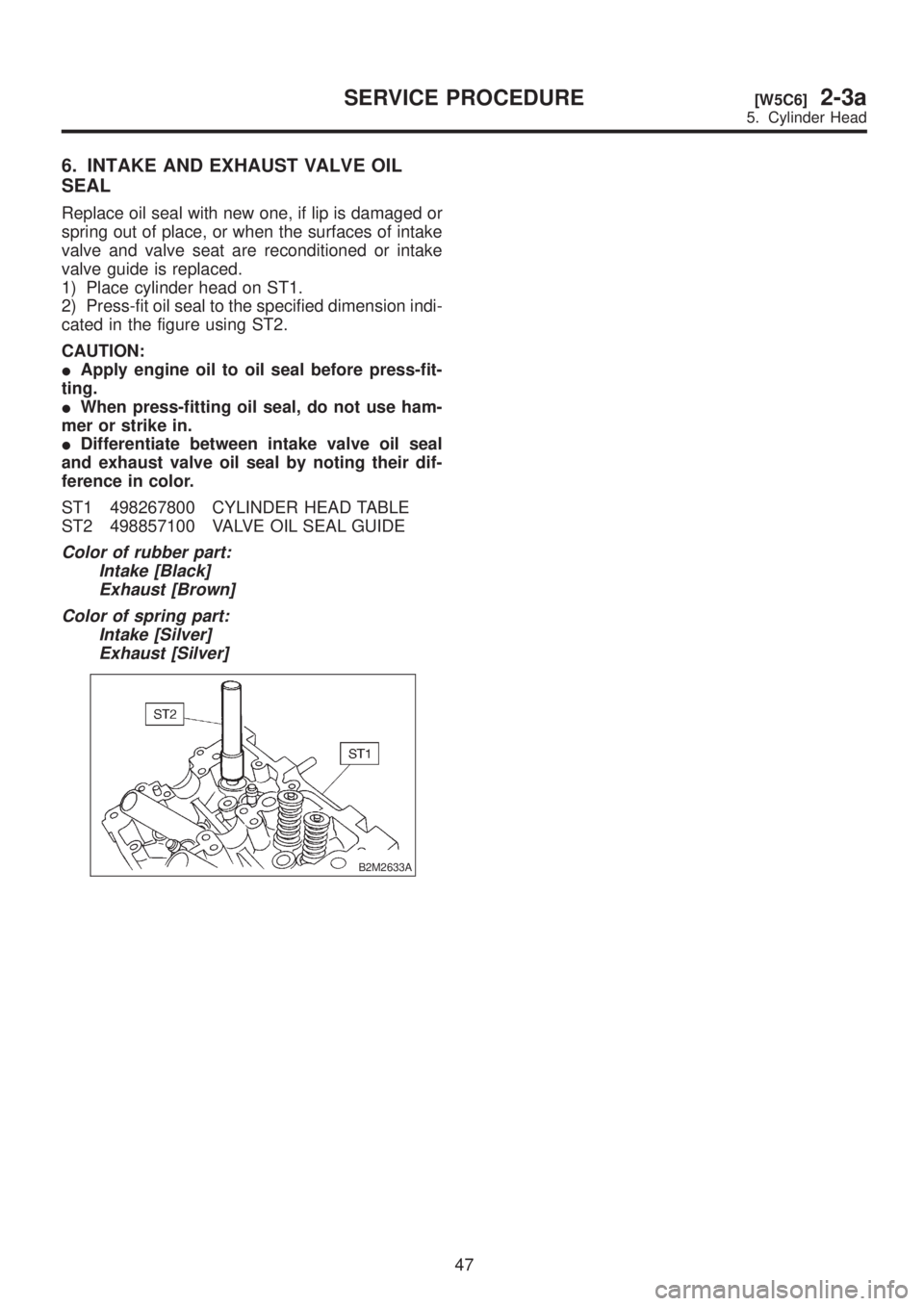
1) Place cylinder head on ST1.
2) Press-fit oil seal to the specified dimension indi-
cated in the figure using ST2.
CAUTION:
IApply engine oil to oil seal before press-fit-
ting.
IWhen press-fitting oil seal, do not use ham-
mer or strike in.
IDifferentiate between intake valve oil seal
and exhaust valve oil seal by noting their dif-
ference in color.
ST1 498267800 CYLINDER HEAD TABLE
ST2 498857100 VALVE OIL SEAL GUIDE
Color of rubber part:
Intake [Black]
Exhaust [Brown]
Color of spring part:
Intake [Silver]
Exhaust [Silver]
B2M2633A
47
[W5C6]2-3aSERVICE PROCEDURE
5. Cylinder Head
Page 102 of 1456
D: ASSEMBLY
B2M2629B
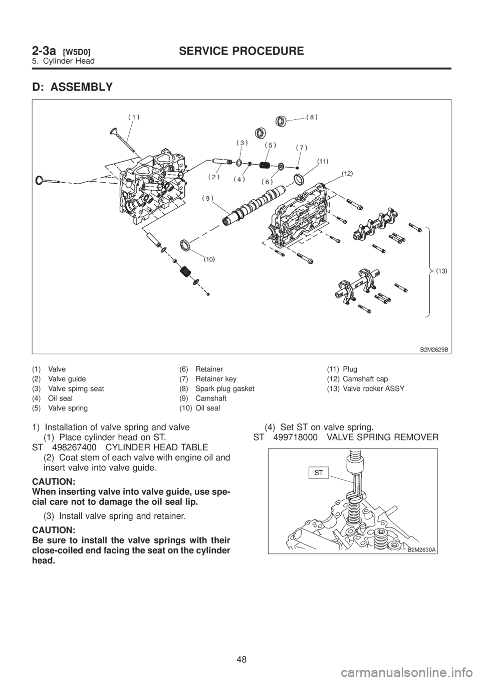
(1) Valve
(2) Valve guide
(3) Valve spirng seat
(4) Oil seal
(5) Valve spring(6) Retainer
(7) Retainer key
(8) Spark plug gasket
(9) Camshaft
(10) Oil seal(11) Plug
(12) Camshaft cap
(13) Valve rocker ASSY
1) Installation of valve spring and valve
(1) Place cylinder head on ST.
ST 498267400 CYLINDER HEAD TABLE
(2) Coat stem of each valve with engine oil and
insert valve into valve guide.
CAUTION:
When inserting valve into valve guide, use spe-
cial care not to damage the oil seal lip.
(3) Install valve spring and retainer.
CAUTION:
Be sure to install the valve springs with their
close-coiled end facing the seat on the cylinder
head.(4) Set ST on valve spring.
ST 499718000 VALVE SPRING REMOVER
B2M2630A
48
2-3a[W5D0]SERVICE PROCEDURE
5. Cylinder Head
Page 103 of 1456
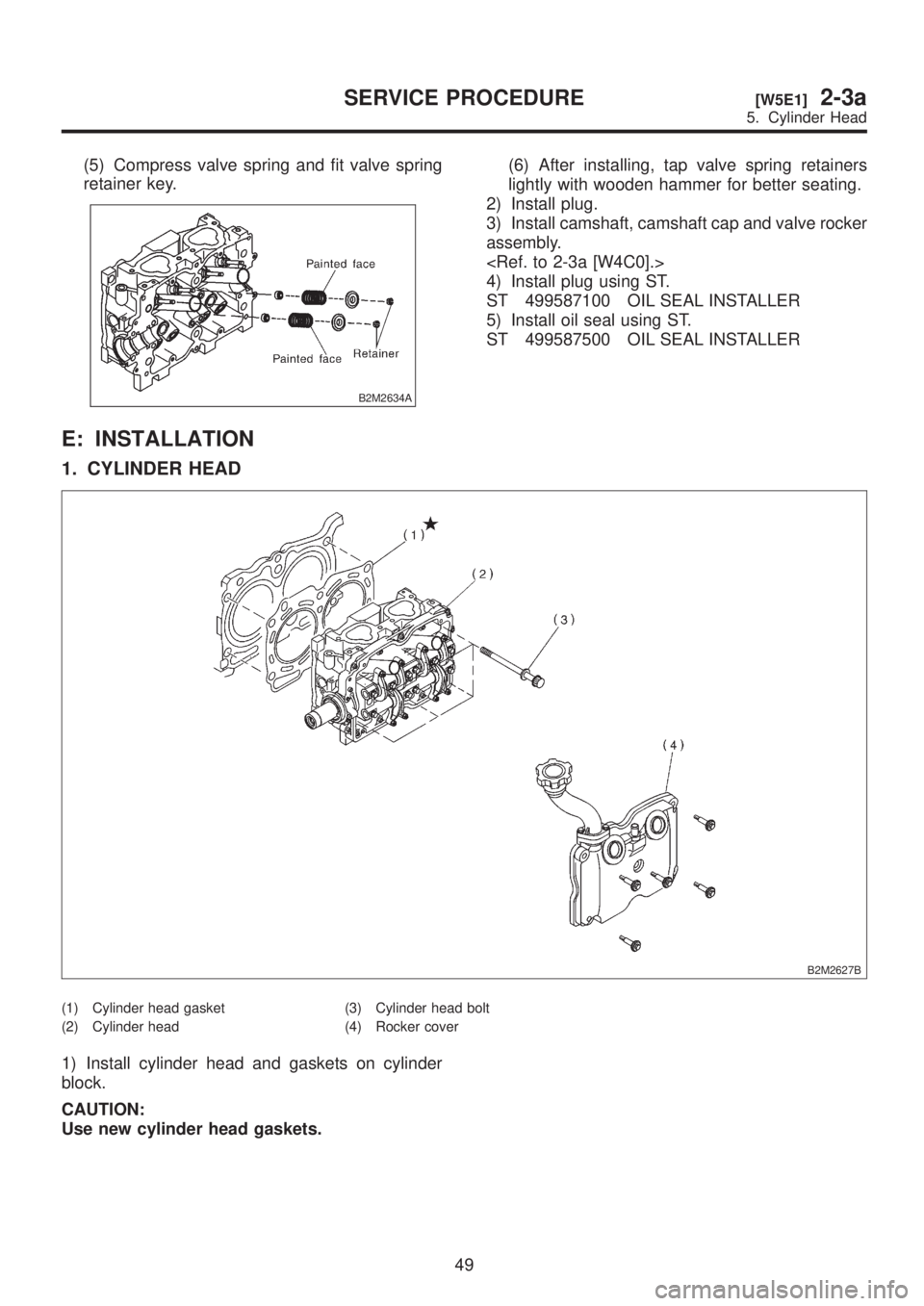
(5) Compress valve spring and fit valve spring
retainer key.
B2M2634A
(6) After installing, tap valve spring retainers
lightly with wooden hammer for better seating.
2) Install plug.
3) Install camshaft, camshaft cap and valve rocker
assembly.
4) Install plug using ST.
ST 499587100 OIL SEAL INSTALLER
5) Install oil seal using ST.
ST 499587500 OIL SEAL INSTALLER
E: INSTALLATION
1. CYLINDER HEAD
B2M2627B
(1) Cylinder head gasket
(2) Cylinder head(3) Cylinder head bolt
(4) Rocker cover
1) Install cylinder head and gaskets on cylinder
block.
CAUTION:
Use new cylinder head gaskets.
49
[W5E1]2-3aSERVICE PROCEDURE
5. Cylinder Head
Page 104 of 1456
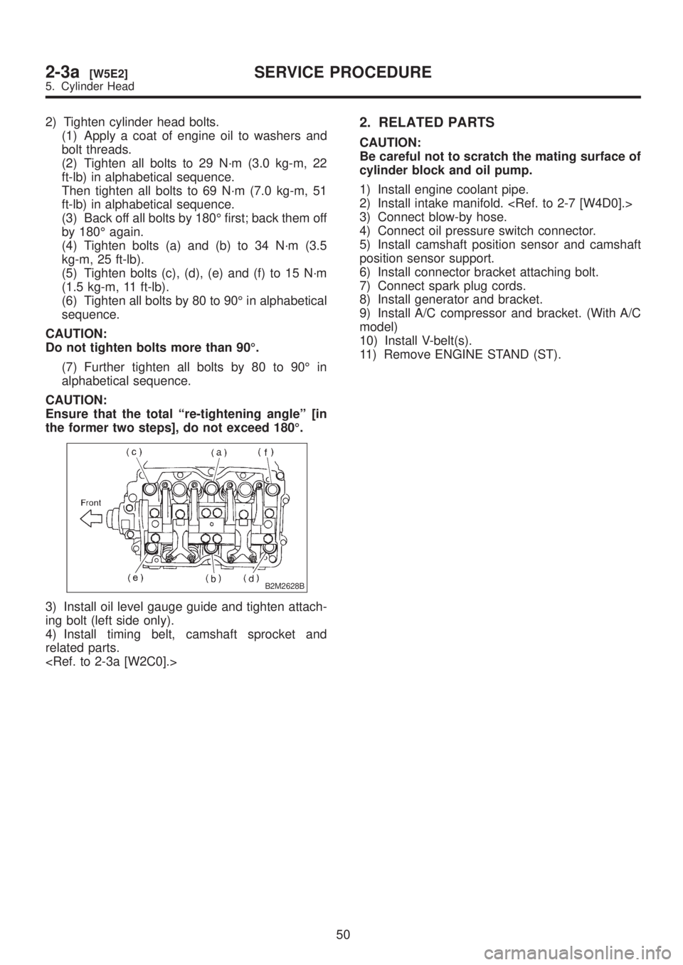
2) Tighten cylinder head bolts.
(1) Apply a coat of engine oil to washers and
bolt threads.
(2) Tighten all bolts to 29 N´m (3.0 kg-m, 22
ft-lb) in alphabetical sequence.
Then tighten all bolts to 69 N´m (7.0 kg-m, 51
ft-lb) in alphabetical sequence.
(3) Back off all bolts by 180É first; back them off
by 180É again.
(4) Tighten bolts (a) and (b) to 34 N´m (3.5
kg-m, 25 ft-lb).
(5) Tighten bolts (c), (d), (e) and (f) to 15 N´m
(1.5 kg-m, 11 ft-lb).
(6) Tighten all bolts by 80 to 90É in alphabetical
sequence.
CAUTION:
Do not tighten bolts more than 90É.
(7) Further tighten all bolts by 80 to 90É in
alphabetical sequence.
CAUTION:
Ensure that the total ªre-tightening angleº [in
the former two steps], do not exceed 180É.
B2M2628B
3) Install oil level gauge guide and tighten attach-
ing bolt (left side only).
4) Install timing belt, camshaft sprocket and
related parts.
2. RELATED PARTS
CAUTION:
Be careful not to scratch the mating surface of
cylinder block and oil pump.
1) Install engine coolant pipe.
2) Install intake manifold.
3) Connect blow-by hose.
4) Connect oil pressure switch connector.
5) Install camshaft position sensor and camshaft
position sensor support.
6) Install connector bracket attaching bolt.
7) Connect spark plug cords.
8) Install generator and bracket.
9) Install A/C compressor and bracket. (With A/C
model)
10) Install V-belt(s).
11) Remove ENGINE STAND (ST).
50
2-3a[W5E2]SERVICE PROCEDURE
5. Cylinder Head
Page 105 of 1456
![SUBARU LEGACY 1999 Service Repair Manual 6. Cylinder Block
A: REMOVAL
1. RELATED PARTS
1) Remove timing belt, camshaft sprockets and
related parts.
<Ref. to 2-3a [W2A0].>
2) Remove cylinder heads. <Ref. to 2-3a
[W5A0].>
3) Remove water pipe. SUBARU LEGACY 1999 Service Repair Manual 6. Cylinder Block
A: REMOVAL
1. RELATED PARTS
1) Remove timing belt, camshaft sprockets and
related parts.
<Ref. to 2-3a [W2A0].>
2) Remove cylinder heads. <Ref. to 2-3a
[W5A0].>
3) Remove water pipe.](/img/17/57435/w960_57435-104.png)
6. Cylinder Block
A: REMOVAL
1. RELATED PARTS
1) Remove timing belt, camshaft sprockets and
related parts.
2) Remove cylinder heads.
3) Remove water pipe.
B2M2638
51
[W6A1]2-3aSERVICE PROCEDURE
6. Cylinder Block
Page 106 of 1456
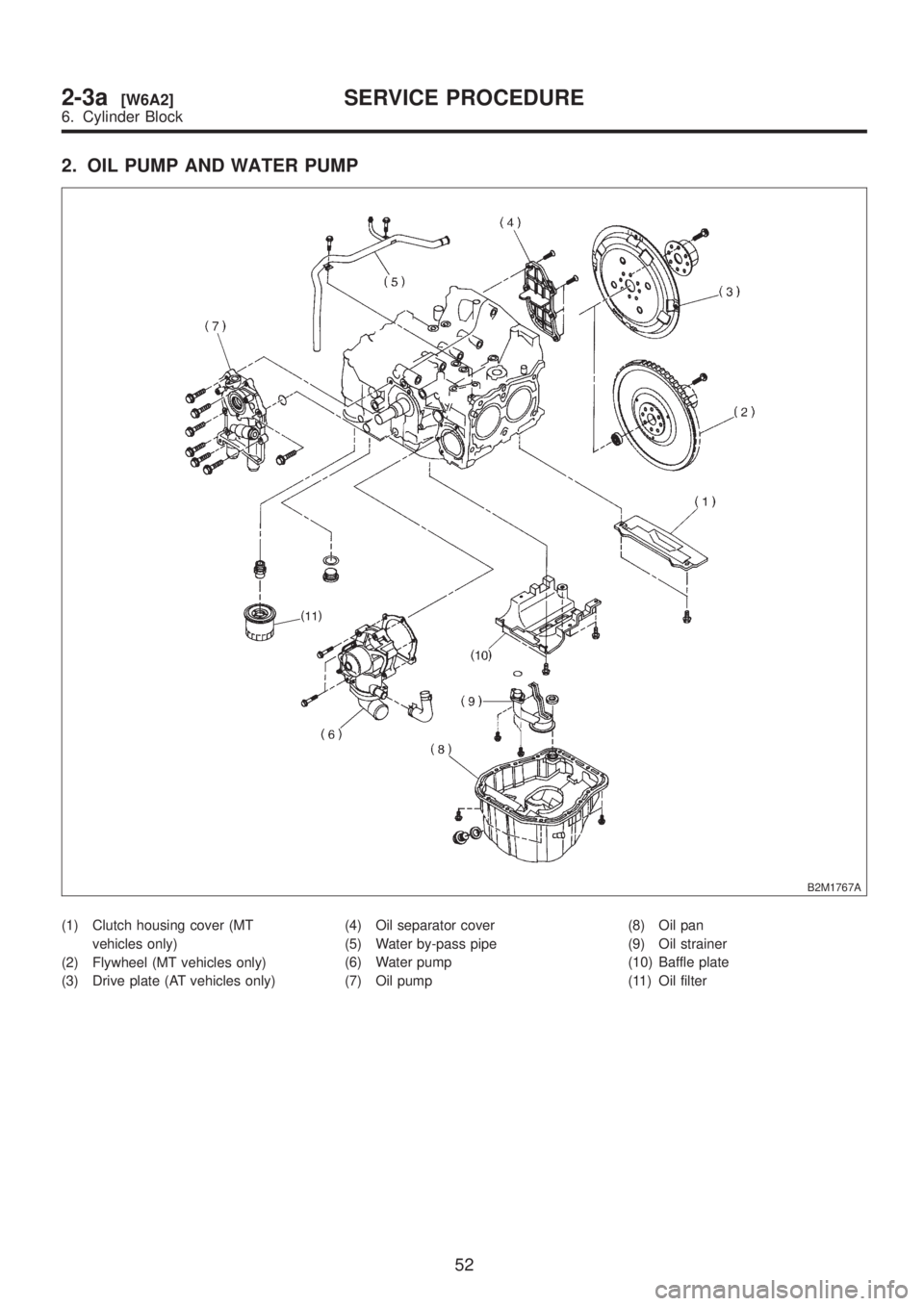
2. OIL PUMP AND WATER PUMP
B2M1767A
(1) Clutch housing cover (MT
vehicles only)
(2) Flywheel (MT vehicles only)
(3) Drive plate (AT vehicles only)(4) Oil separator cover
(5) Water by-pass pipe
(6) Water pump
(7) Oil pump(8) Oil pan
(9) Oil strainer
(10) Baffle plate
(11) Oil filter
52
2-3a[W6A2]SERVICE PROCEDURE
6. Cylinder Block
Page 107 of 1456
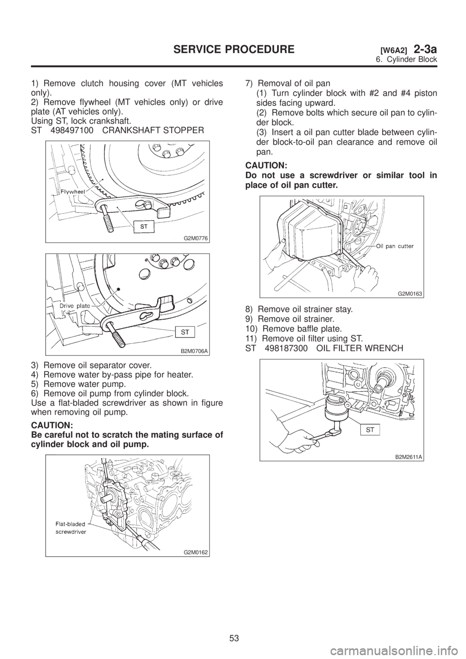
1) Remove clutch housing cover (MT vehicles
only).
2) Remove flywheel (MT vehicles only) or drive
plate (AT vehicles only).
Using ST, lock crankshaft.
ST 498497100 CRANKSHAFT STOPPER
G2M0776
B2M0706A
3) Remove oil separator cover.
4) Remove water by-pass pipe for heater.
5) Remove water pump.
6) Remove oil pump from cylinder block.
Use a flat-bladed screwdriver as shown in figure
when removing oil pump.
CAUTION:
Be careful not to scratch the mating surface of
cylinder block and oil pump.
G2M0162
7) Removal of oil pan
(1) Turn cylinder block with #2 and #4 piston
sides facing upward.
(2) Remove bolts which secure oil pan to cylin-
der block.
(3) Insert a oil pan cutter blade between cylin-
der block-to-oil pan clearance and remove oil
pan.
CAUTION:
Do not use a screwdriver or similar tool in
place of oil pan cutter.
G2M0163
8) Remove oil strainer stay.
9) Remove oil strainer.
10) Remove baffle plate.
11) Remove oil filter using ST.
ST 498187300 OIL FILTER WRENCH
B2M2611A
53
[W6A2]2-3aSERVICE PROCEDURE
6. Cylinder Block
Page 108 of 1456
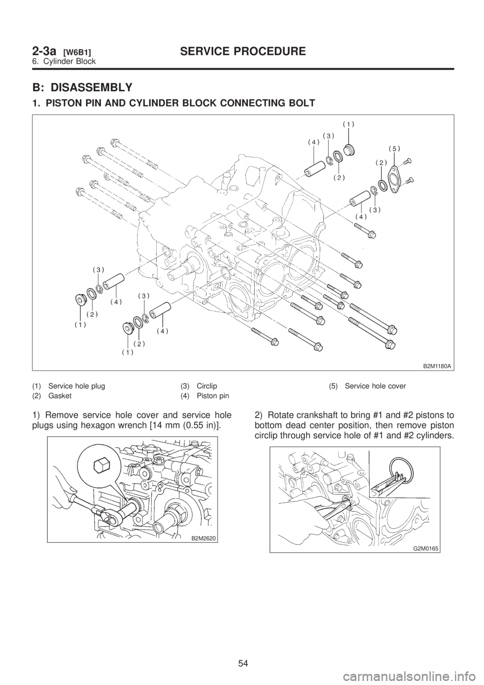
B: DISASSEMBLY
1. PISTON PIN AND CYLINDER BLOCK CONNECTING BOLT
B2M1180A
(1) Service hole plug
(2) Gasket(3) Circlip
(4) Piston pin(5) Service hole cover
1) Remove service hole cover and service hole
plugs using hexagon wrench [14 mm (0.55 in)].
B2M2620
2) Rotate crankshaft to bring #1 and #2 pistons to
bottom dead center position, then remove piston
circlip through service hole of #1 and #2 cylinders.
G2M0165
54
2-3a[W6B1]SERVICE PROCEDURE
6. Cylinder Block
Page 109 of 1456
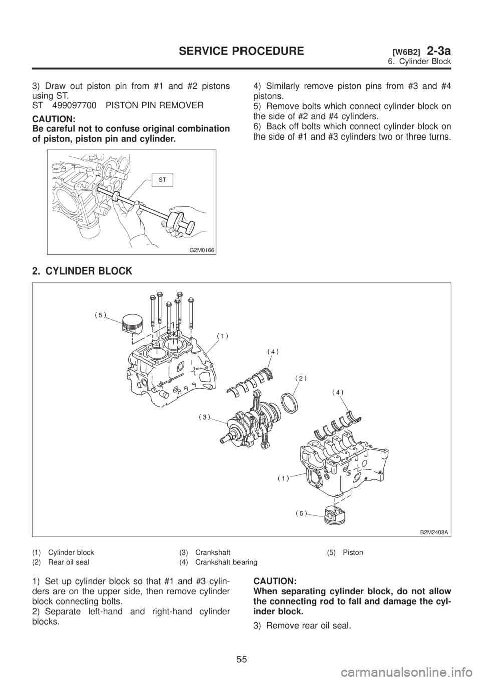
3) Draw out piston pin from #1 and #2 pistons
using ST.
ST 499097700 PISTON PIN REMOVER
CAUTION:
Be careful not to confuse original combination
of piston, piston pin and cylinder.
G2M0166
4) Similarly remove piston pins from #3 and #4
pistons.
5) Remove bolts which connect cylinder block on
the side of #2 and #4 cylinders.
6) Back off bolts which connect cylinder block on
the side of #1 and #3 cylinders two or three turns.
2. CYLINDER BLOCK
B2M2408A
(1) Cylinder block
(2) Rear oil seal(3) Crankshaft
(4) Crankshaft bearing(5) Piston
1) Set up cylinder block so that #1 and #3 cylin-
ders are on the upper side, then remove cylinder
block connecting bolts.
2) Separate left-hand and right-hand cylinder
blocks.CAUTION:
When separating cylinder block, do not allow
the connecting rod to fall and damage the cyl-
inder block.
3) Remove rear oil seal.
55
[W6B2]2-3aSERVICE PROCEDURE
6. Cylinder Block
Page 110 of 1456
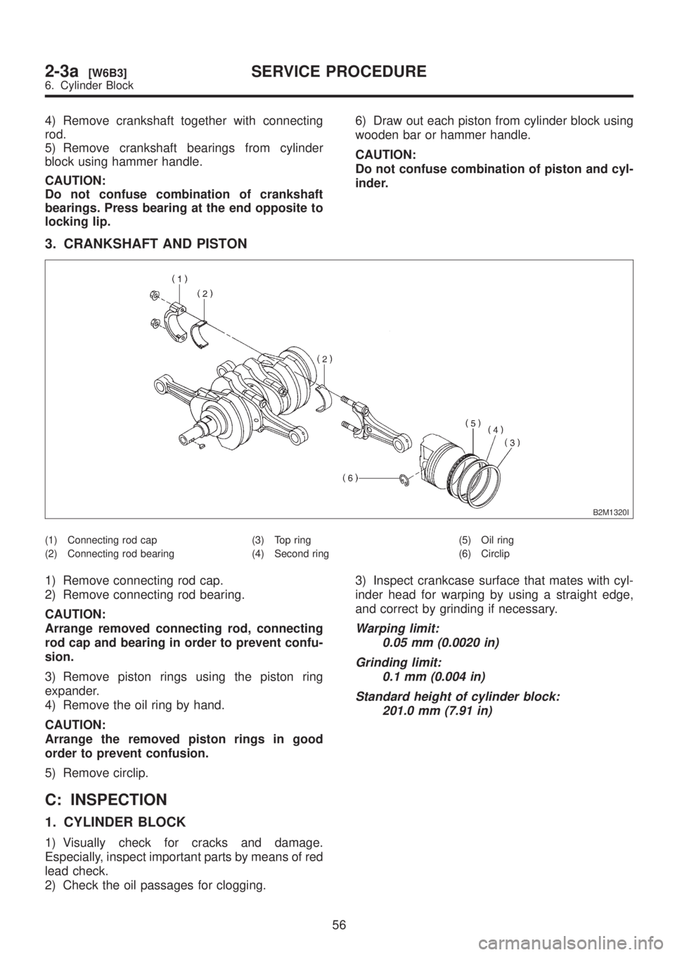
4) Remove crankshaft together with connecting
rod.
5) Remove crankshaft bearings from cylinder
block using hammer handle.
CAUTION:
Do not confuse combination of crankshaft
bearings. Press bearing at the end opposite to
locking lip.6) Draw out each piston from cylinder block using
wooden bar or hammer handle.
CAUTION:
Do not confuse combination of piston and cyl-
inder.
3. CRANKSHAFT AND PISTON
B2M1320I
(1) Connecting rod cap
(2) Connecting rod bearing(3) Top ring
(4) Second ring(5) Oil ring
(6) Circlip
1) Remove connecting rod cap.
2) Remove connecting rod bearing.
CAUTION:
Arrange removed connecting rod, connecting
rod cap and bearing in order to prevent confu-
sion.
3) Remove piston rings using the piston ring
expander.
4) Remove the oil ring by hand.
CAUTION:
Arrange the removed piston rings in good
order to prevent confusion.
5) Remove circlip.
C: INSPECTION
1. CYLINDER BLOCK
1) Visually check for cracks and damage.
Especially, inspect important parts by means of red
lead check.
2) Check the oil passages for clogging.3) Inspect crankcase surface that mates with cyl-
inder head for warping by using a straight edge,
and correct by grinding if necessary.
Warping limit:
0.05 mm (0.0020 in)
Grinding limit:
0.1 mm (0.004 in)
Standard height of cylinder block:
201.0 mm (7.91 in)
56
2-3a[W6B3]SERVICE PROCEDURE
6. Cylinder Block