height SUBARU LEGACY 1999 Service User Guide
[x] Cancel search | Manufacturer: SUBARU, Model Year: 1999, Model line: LEGACY, Model: SUBARU LEGACY 1999Pages: 1456, PDF Size: 59.93 MB
Page 163 of 1456
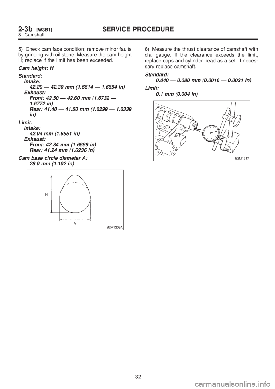
5) Check cam face condition; remove minor faults
by grinding with oil stone. Measure the cam height
H; replace if the limit has been exceeded.
Cam height: H
Standard:
Intake:
42.20 Ð 42.30 mm (1.6614 Ð 1.6654 in)
Exhaust:
Front: 42.50 Ð 42.60 mm (1.6732 Ð
1.6772 in)
Rear: 41.40 Ð 41.50 mm (1.6299 Ð 1.6339
in)
Limit:
Intake:
42.04 mm (1.6551 in)
Exhaust:
Front: 42.34 mm (1.6669 in)
Rear: 41.24 mm (1.6236 in)
Cam base circle diameter A:
28.0 mm (1.102 in)
B2M1209A
6) Measure the thrust clearance of camshaft with
dial gauge. If the clearance exceeds the limit,
replace caps and cylinder head as a set. If neces-
sary replace camshaft.
Standard:
0.040 Ð 0.080 mm (0.0016 Ð 0.0031 in)
Limit:
0.1 mm (0.004 in)
B2M1217
32
2-3b[W3B1]SERVICE PROCEDURE
3. Camshaft
Page 169 of 1456
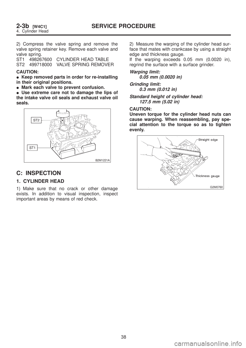
2) Compress the valve spring and remove the
valve spring retainer key. Remove each valve and
valve spring.
ST1 498267600 CYLINDER HEAD TABLE
ST2 499718000 VALVE SPRING REMOVER
CAUTION:
IKeep removed parts in order for re-installing
in their original positions.
IMark each valve to prevent confusion.
IUse extreme care not to damage the lips of
the intake valve oil seals and exhaust valve oil
seals.
B2M1221A
C: INSPECTION
1. CYLINDER HEAD
1) Make sure that no crack or other damage
exists. In addition to visual inspection, inspect
important areas by means of red check.2) Measure the warping of the cylinder head sur-
face that mates with crankcase by using a straight
edge and thickness gauge.
If the warping exceeds 0.05 mm (0.0020 in),
regrind the surface with a surface grinder.
Warping limit:
0.05 mm (0.0020 in)
Grinding limit:
0.3 mm (0.012 in)
Standard height of cylinder head:
127.5 mm (5.02 in)
CAUTION:
Uneven torque for the cylinder head nuts can
cause warping. When reassembling, pay spe-
cial attention to the torque so as to tighten
evenly.
G2M0760
38
2-3b[W4C1]SERVICE PROCEDURE
4. Cylinder Head
Page 172 of 1456
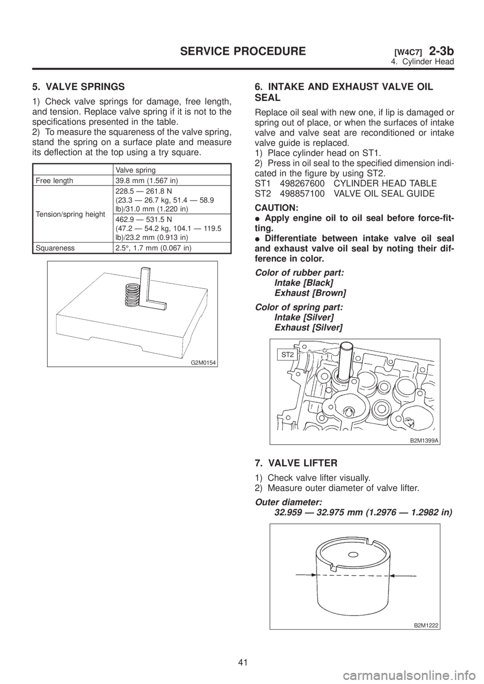
5. VALVE SPRINGS
1) Check valve springs for damage, free length,
and tension. Replace valve spring if it is not to the
specifications presented in the table.
2) To measure the squareness of the valve spring,
stand the spring on a surface plate and measure
its deflection at the top using a try square.
Valve spring
Free length 39.8 mm (1.567 in)
Tension/spring height228.5 Ð 261.8 N
(23.3 Ð 26.7 kg, 51.4 Ð 58.9
lb)/31.0 mm (1.220 in)
462.9 Ð 531.5 N
(47.2 Ð 54.2 kg, 104.1 Ð 119.5
lb)/23.2 mm (0.913 in)
Squareness 2.5É, 1.7 mm (0.067 in)
G2M0154
6. INTAKE AND EXHAUST VALVE OIL
SEAL
Replace oil seal with new one, if lip is damaged or
spring out of place, or when the surfaces of intake
valve and valve seat are reconditioned or intake
valve guide is replaced.
1) Place cylinder head on ST1.
2) Press in oil seal to the specified dimension indi-
cated in the figure by using ST2.
ST1 498267600 CYLINDER HEAD TABLE
ST2 498857100 VALVE OIL SEAL GUIDE
CAUTION:
IApply engine oil to oil seal before force-fit-
ting.
IDifferentiate between intake valve oil seal
and exhaust valve oil seal by noting their dif-
ference in color.
Color of rubber part:
Intake [Black]
Exhaust [Brown]
Color of spring part:
Intake [Silver]
Exhaust [Silver]
B2M1399A
7. VALVE LIFTER
1) Check valve lifter visually.
2) Measure outer diameter of valve lifter.
Outer diameter:
32.959 Ð 32.975 mm (1.2976 Ð 1.2982 in)
B2M1222
41
[W4C7]2-3bSERVICE PROCEDURE
4. Cylinder Head
Page 186 of 1456
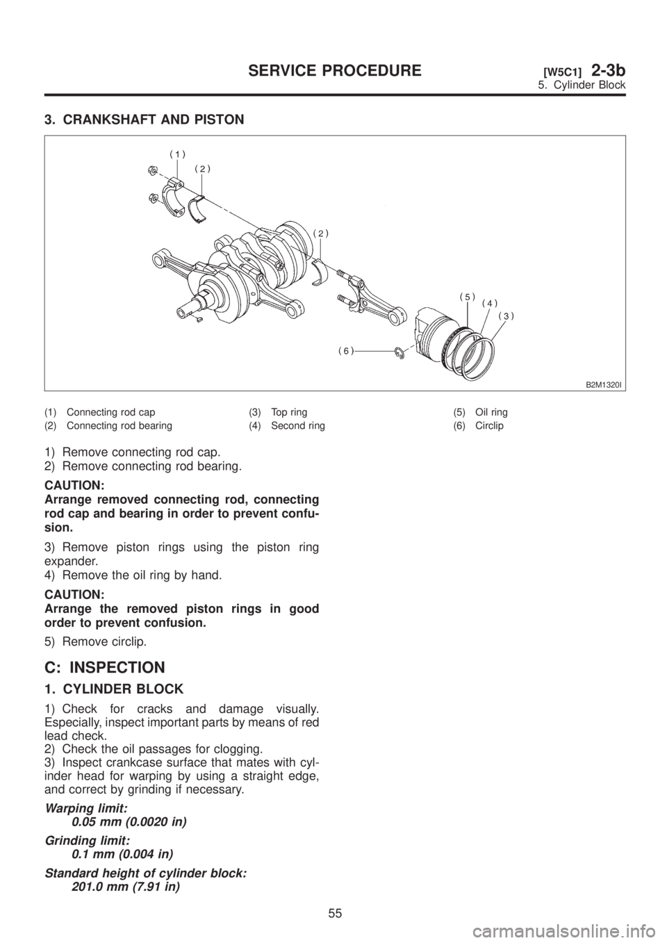
3. CRANKSHAFT AND PISTON
B2M1320I
(1) Connecting rod cap
(2) Connecting rod bearing(3) Top ring
(4) Second ring(5) Oil ring
(6) Circlip
1) Remove connecting rod cap.
2) Remove connecting rod bearing.
CAUTION:
Arrange removed connecting rod, connecting
rod cap and bearing in order to prevent confu-
sion.
3) Remove piston rings using the piston ring
expander.
4) Remove the oil ring by hand.
CAUTION:
Arrange the removed piston rings in good
order to prevent confusion.
5) Remove circlip.
C: INSPECTION
1. CYLINDER BLOCK
1) Check for cracks and damage visually.
Especially, inspect important parts by means of red
lead check.
2) Check the oil passages for clogging.
3) Inspect crankcase surface that mates with cyl-
inder head for warping by using a straight edge,
and correct by grinding if necessary.
Warping limit:
0.05 mm (0.0020 in)
Grinding limit:
0.1 mm (0.004 in)
Standard height of cylinder block:
201.0 mm (7.91 in)
55
[W5C1]2-3bSERVICE PROCEDURE
5. Cylinder Block
Page 187 of 1456
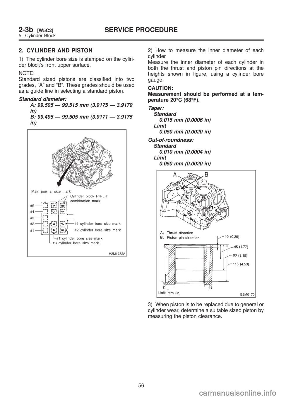
2. CYLINDER AND PISTON
1) The cylinder bore size is stamped on the cylin-
der block's front upper surface.
NOTE:
Standard sized pistons are classified into two
grades, ªAº and ªBº. These grades should be used
as a guide line in selecting a standard piston.
Standard diameter:
A: 99.505 Ð 99.515 mm (3.9175 Ð 3.9179
in)
B: 99.495 Ð 99.505 mm (3.9171 Ð 3.9175
in)
H2M1732A
2) How to measure the inner diameter of each
cylinder
Measure the inner diameter of each cylinder in
both the thrust and piston pin directions at the
heights shown in figure, using a cylinder bore
gauge.
CAUTION:
Measurement should be performed at a tem-
perature 20ÉC (68ÉF).
Taper:
Standard
0.015 mm (0.0006 in)
Limit
0.050 mm (0.0020 in)
Out-of-roundness:
Standard
0.010 mm (0.0004 in)
Limit
0.050 mm (0.0020 in)
G2M0170
3) When piston is to be replaced due to general or
cylinder wear, determine a suitable sized piston by
measuring the piston clearance.
56
2-3b[W5C2]SERVICE PROCEDURE
5. Cylinder Block
Page 188 of 1456
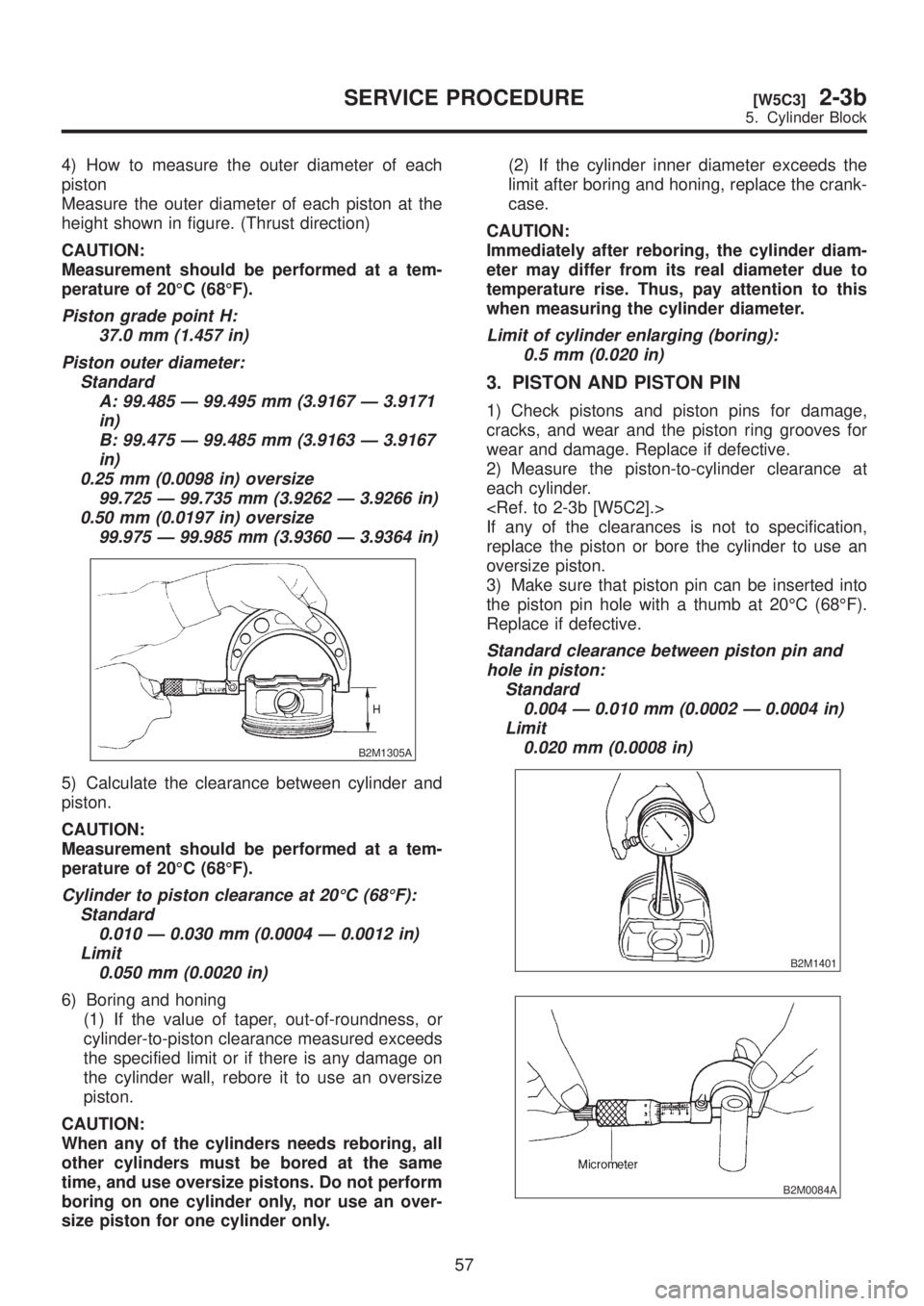
4) How to measure the outer diameter of each
piston
Measure the outer diameter of each piston at the
height shown in figure. (Thrust direction)
CAUTION:
Measurement should be performed at a tem-
perature of 20ÉC (68ÉF).
Piston grade point H:
37.0 mm (1.457 in)
Piston outer diameter:
Standard
A: 99.485 Ð 99.495 mm (3.9167 Ð 3.9171
in)
B: 99.475 Ð 99.485 mm (3.9163 Ð 3.9167
in)
0.25 mm (0.0098 in) oversize
99.725 Ð 99.735 mm (3.9262 Ð 3.9266 in)
0.50 mm (0.0197 in) oversize
99.975 Ð 99.985 mm (3.9360 Ð 3.9364 in)
B2M1305A
5) Calculate the clearance between cylinder and
piston.
CAUTION:
Measurement should be performed at a tem-
perature of 20ÉC (68ÉF).
Cylinder to piston clearance at 20ÉC (68ÉF):
Standard
0.010 Ð 0.030 mm (0.0004 Ð 0.0012 in)
Limit
0.050 mm (0.0020 in)
6) Boring and honing
(1) If the value of taper, out-of-roundness, or
cylinder-to-piston clearance measured exceeds
the specified limit or if there is any damage on
the cylinder wall, rebore it to use an oversize
piston.
CAUTION:
When any of the cylinders needs reboring, all
other cylinders must be bored at the same
time, and use oversize pistons. Do not perform
boring on one cylinder only, nor use an over-
size piston for one cylinder only.(2) If the cylinder inner diameter exceeds the
limit after boring and honing, replace the crank-
case.
CAUTION:
Immediately after reboring, the cylinder diam-
eter may differ from its real diameter due to
temperature rise. Thus, pay attention to this
when measuring the cylinder diameter.
Limit of cylinder enlarging (boring):
0.5 mm (0.020 in)
3. PISTON AND PISTON PIN
1) Check pistons and piston pins for damage,
cracks, and wear and the piston ring grooves for
wear and damage. Replace if defective.
2) Measure the piston-to-cylinder clearance at
each cylinder.
If any of the clearances is not to specification,
replace the piston or bore the cylinder to use an
oversize piston.
3) Make sure that piston pin can be inserted into
the piston pin hole with a thumb at 20ÉC (68ÉF).
Replace if defective.
Standard clearance between piston pin and
hole in piston:
Standard
0.004 Ð 0.010 mm (0.0002 Ð 0.0004 in)
Limit
0.020 mm (0.0008 in)
B2M1401
B2M0084A
57
[W5C3]2-3bSERVICE PROCEDURE
5. Cylinder Block
Page 517 of 1456
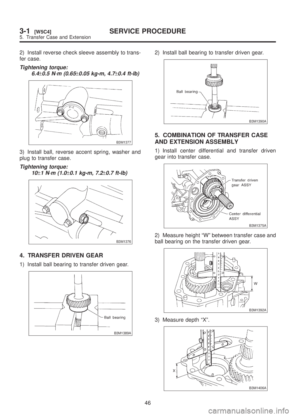
2) Install reverse check sleeve assembly to trans-
fer case.
Tightening torque:
6.4
±0.5 N´m (0.65±0.05 kg-m, 4.7±0.4 ft-lb)
B3M1377
3) Install ball, reverse accent spring, washer and
plug to transfer case.
Tightening torque:
10
±1 N´m (1.0±0.1 kg-m, 7.2±0.7 ft-lb)
B3M1376
4. TRANSFER DRIVEN GEAR
1) Install ball bearing to transfer driven gear.
B3M1389A
2) Install ball bearing to transfer driven gear.
B3M1390A
5. COMBINATION OF TRANSFER CASE
AND EXTENSION ASSEMBLY
1) Install center differential and transfer driven
gear into transfer case.
B3M1375A
2) Measure height ªWº between transfer case and
ball bearing on the transfer driven gear.
B3M1392A
3) Measure depth ªXº.
B3M1406A
46
3-1[W5C4]SERVICE PROCEDURE
5. Transfer Case and Extension
Page 587 of 1456
![SUBARU LEGACY 1999 Service User Guide Checking item Contact pattern Corrective action
Tooth contact
Tooth contact pattern is slightly shifted
toward to under no-load rotation.
[When loaded, contact pattern moves
toward heel.]
B3M0317A
Ð](/img/17/57435/w960_57435-586.png "SUBARU LEGACY 1999 Service User Guide Checking item Contact pattern Corrective action
Tooth contact
Tooth contact pattern is slightly shifted
toward to under no-load rotation.
[When loaded, contact pattern moves
toward heel.]
B3M0317A
Ð")
Checking item Contact pattern Corrective action
Tooth contact
Tooth contact pattern is slightly shifted
toward to under no-load rotation.
[When loaded, contact pattern moves
toward heel.]
B3M0317A
Ð
Face contact
Backlash is too large.This may cause noise and chipping at
tooth ends.
B3M0319
Increase thickness of drive pinion height
adjusting shim in order to bring drive pin-
ion close to crown gear.
B3M0323
Flank contact Backlash is too small. This may cause noise and stepped wear
on surfaces.
B3M0320
Reduce thickness of drive pinion height
adjusting shim in order to move drive
pinion away from crown gear.
B3M0324
Toe contact
(Inside end contact)
Contact areas is small.This may cause chipping at toe.
B3M0321
Adjust as for flank contact.
B3M0324
Heel contact (Outside end contact)
Contact area is small.This may cause chipping at heel ends.
B3M0322
Adjust as for face contact.
B3M0323
: Adjusting direction of drive pinion: Adjusting direction of crown gear
58
3-2[W11C1]SERVICE PROCEDURE
11. Overall Transmission
Page 595 of 1456
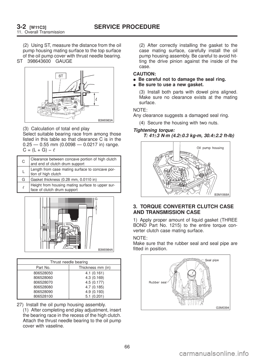
(2) Using ST, measure the distance from the oil
pump housing mating surface to the top surface
of the oil pump cover with thrust needle bearing.
ST 398643600 GAUGE
B3M0983A
(3) Calculation of total end play
Select suitable bearing race from among those
listed in this table so that clearance C is in the
0.25 Ð 0.55 mm (0.0098 Ð 0.0217 in) range.
C=(L+G)þ
CClearance between concave portion of high clutch
and end of clutch drum support
LLength from case mating surface to concave por-
tion of high clutch
G Gasket thickness (0.28 mm, 0.0110 in)
Height from housing mating surface to upper sur-
face of clutch drum support
B3M0984A
Thrust needle bearing
Part No. Thickness mm (in)
806528050
806528060
806528070
806528080
806528090
8065281004.1 (0.161)
4.3 (0.169)
4.5 (0.177)
4.7 (0.185)
4.9 (0.193)
5.1 (0.201)
27) Install the oil pump housing assembly.
(1) After completing end play adjustment, insert
the bearing race in the recess of the high clutch.
Attach the thrust needle bearing to the oil pump
cover with vaseline.(2) After correctly installing the gasket to the
case mating surface, carefully install the oil
pump housing assembly. Be careful to avoid hit-
ting the drive pinion against the inside of the
case.
CAUTION:
IBe careful not to damage the seal ring.
IBe sure to use a new gasket.
(3) Install both parts with dowel pins aligned.
Make sure no clearance exists at the mating
surface.
NOTE:
Any clearance suggests a damaged seal ring.
(4) Secure the housing with two nuts.
Tightening torque:
T: 4 1
±3 N´m (4.2±0.3 kg-m, 30.4±2.2 ft-lb)
B3M1068A
3. TORQUE CONVERTER CLUTCH CASE
AND TRANSMISSION CASE
1) Apply proper amount of liquid gasket (THREE
BOND Part No. 1215) to the entire torque con-
verter clutch case mating surface.
NOTE:
Make sure that the rubber seal and seal pipe are
fitted in position.
G3M0394
66
3-2[W11C3]SERVICE PROCEDURE
11. Overall Transmission
Page 599 of 1456
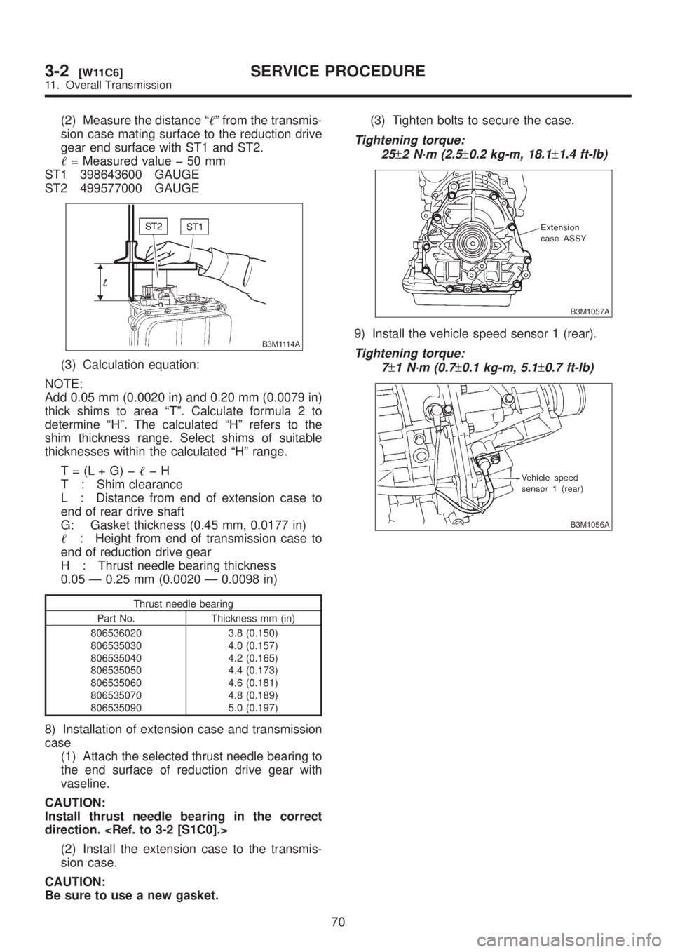
(2) Measure the distance ªº from the transmis-
sion case mating surface to the reduction drive
gear end surface with ST1 and ST2.
= Measured value þ 50 mm
ST1 398643600 GAUGE
ST2 499577000 GAUGE
B3M1114A
(3) Calculation equation:
NOTE:
Add 0.05 mm (0.0020 in) and 0.20 mm (0.0079 in)
thick shims to area ªTº. Calculate formula 2 to
determine ªHº. The calculated ªHº refers to the
shim thickness range. Select shims of suitable
thicknesses within the calculated ªHº range.
T=(L+G)þþH
T : Shim clearance
L : Distance from end of extension case to
end of rear drive shaft
G: Gasket thickness (0.45 mm, 0.0177 in)
: Height from end of transmission case to
end of reduction drive gear
H : Thrust needle bearing thickness
0.05 Ð 0.25 mm (0.0020 Ð 0.0098 in)
Thrust needle bearing
Part No. Thickness mm (in)
806536020
806535030
806535040
806535050
806535060
806535070
8065350903.8 (0.150)
4.0 (0.157)
4.2 (0.165)
4.4 (0.173)
4.6 (0.181)
4.8 (0.189)
5.0 (0.197)
8) Installation of extension case and transmission
case
(1) Attach the selected thrust needle bearing to
the end surface of reduction drive gear with
vaseline.
CAUTION:
Install thrust needle bearing in the correct
direction.
(2) Install the extension case to the transmis-
sion case.
CAUTION:
Be sure to use a new gasket.(3) Tighten bolts to secure the case.
Tightening torque:
25
±2 N´m (2.5±0.2 kg-m, 18.1±1.4 ft-lb)
B3M1057A
9) Install the vehicle speed sensor 1 (rear).
Tightening torque:
7
±1 N´m (0.7±0.1 kg-m, 5.1±0.7 ft-lb)
B3M1056A
70
3-2[W11C6]SERVICE PROCEDURE
11. Overall Transmission