height SUBARU LEGACY 1999 Service Service Manual
[x] Cancel search | Manufacturer: SUBARU, Model Year: 1999, Model line: LEGACY, Model: SUBARU LEGACY 1999Pages: 1456, PDF Size: 59.93 MB
Page 713 of 1456
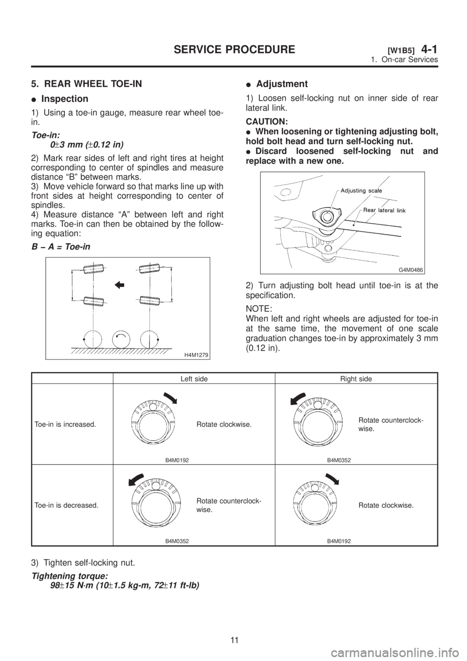
5. REAR WHEEL TOE-IN
IInspection
1) Using a toe-in gauge, measure rear wheel toe-
in.
Toe-in:
0
±3mm(±0.12 in)
2) Mark rear sides of left and right tires at height
corresponding to center of spindles and measure
distance ªBº between marks.
3) Move vehicle forward so that marks line up with
front sides at height corresponding to center of
spindles.
4) Measure distance ªAº between left and right
marks. Toe-in can then be obtained by the follow-
ing equation:
B þ A = Toe-in
H4M1279
IAdjustment
1) Loosen self-locking nut on inner side of rear
lateral link.
CAUTION:
IWhen loosening or tightening adjusting bolt,
hold bolt head and turn self-locking nut.
IDiscard loosened self-locking nut and
replace with a new one.
G4M0486
2) Turn adjusting bolt head until toe-in is at the
specification.
NOTE:
When left and right wheels are adjusted for toe-in
at the same time, the movement of one scale
graduation changes toe-in by approximately 3 mm
(0.12 in).
Left side Right side
Toe-in is increased.
B4M0192
Rotate clockwise.
B4M0352
Rotate counterclock-
wise.
Toe-in is decreased.
B4M0352
Rotate counterclock-
wise.
B4M0192
Rotate clockwise.
3) Tighten self-locking nut.
Tightening torque:
98
±15 N´m (10±1.5 kg-m, 72±11 ft-lb)
11
[W1B5]4-1SERVICE PROCEDURE
1. On-car Services
Page 744 of 1456
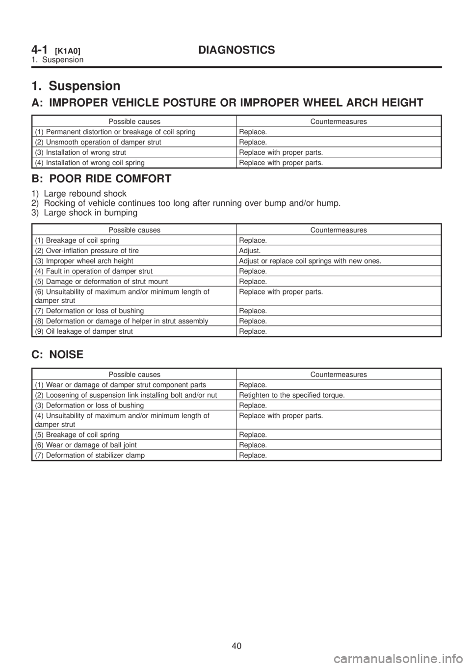
1. Suspension
A: IMPROPER VEHICLE POSTURE OR IMPROPER WHEEL ARCH HEIGHT
Possible causes Countermeasures
(1) Permanent distortion or breakage of coil spring Replace.
(2) Unsmooth operation of damper strut Replace.
(3) Installation of wrong strut Replace with proper parts.
(4) Installation of wrong coil spring Replace with proper parts.
B: POOR RIDE COMFORT
1) Large rebound shock
2) Rocking of vehicle continues too long after running over bump and/or hump.
3) Large shock in bumping
Possible causes Countermeasures
(1) Breakage of coil spring Replace.
(2) Over-inflation pressure of tire Adjust.
(3) Improper wheel arch height Adjust or replace coil springs with new ones.
(4) Fault in operation of damper strut Replace.
(5) Damage or deformation of strut mount Replace.
(6) Unsuitability of maximum and/or minimum length of
damper strutReplace with proper parts.
(7) Deformation or loss of bushing Replace.
(8) Deformation or damage of helper in strut assembly Replace.
(9) Oil leakage of damper strut Replace.
C: NOISE
Possible causes Countermeasures
(1) Wear or damage of damper strut component parts Replace.
(2) Loosening of suspension link installing bolt and/or nut Retighten to the specified torque.
(3) Deformation or loss of bushing Replace.
(4) Unsuitability of maximum and/or minimum length of
damper strutReplace with proper parts.
(5) Breakage of coil spring Replace.
(6) Wear or damage of ball joint Replace.
(7) Deformation of stabilizer clamp Replace.
40
4-1[K1A0]DIAGNOSTICS
1. Suspension
Page 863 of 1456
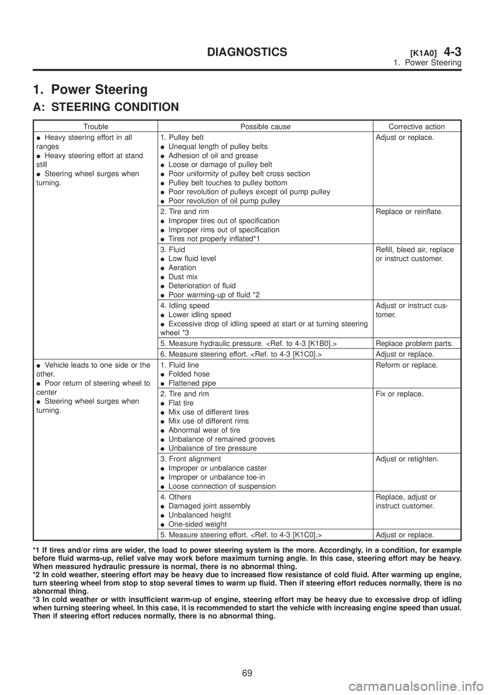
1. Power Steering
A: STEERING CONDITION
Trouble Possible cause Corrective action
IHeavy steering effort in all
ranges
IHeavy steering effort at stand
still
ISteering wheel surges when
turning.1. Pulley belt
IUnequal length of pulley belts
IAdhesion of oil and grease
ILoose or damage of pulley belt
IPoor uniformity of pulley belt cross section
IPulley belt touches to pulley bottom
IPoor revolution of pulleys except oil pump pulley
IPoor revolution of oil pump pulleyAdjust or replace.
2. Tire and rim
IImproper tires out of specification
IImproper rims out of specification
ITires not properly inflated*1Replace or reinflate.
3. Fluid
ILow fluid level
IAeration
IDust mix
IDeterioration of fluid
IPoor warming-up of fluid *2Refill, bleed air, replace
or instruct customer.
4. Idling speed
ILower idling speed
IExcessive drop of idling speed at start or at turning steering
wheel *3Adjust or instruct cus-
tomer.
5. Measure hydraulic pressure.
6. Measure steering effort.
IVehicle leads to one side or the
other.
IPoor return of steering wheel to
center
ISteering wheel surges when
turning.1. Fluid line
IFolded hose
IFlattened pipeReform or replace.
2. Tire and rim
IFlat tire
IMix use of different tires
IMix use of different rims
IAbnormal wear of tire
IUnbalance of remained grooves
IUnbalance of tire pressureFix or replace.
3. Front alignment
IImproper or unbalance caster
IImproper or unbalance toe-in
ILoose connection of suspensionAdjust or retighten.
4. Others
IDamaged joint assembly
IUnbalanced height
IOne-sided weightReplace, adjust or
instruct customer.
5. Measure steering effort.
*1 If tires and/or rims are wider, the load to power steering system is the more. Accordingly, in a condition, for example
before fluid warms-up, relief valve may work before maximum turning angle. In this case, steering effort may be heavy.
When measured hydraulic pressure is normal, there is no abnormal thing.
*2 In cold weather, steering effort may be heavy due to increased flow resistance of cold fluid. After warming up engine,
turn steering wheel from stop to stop several times to warm up fluid. Then if steering effort reduces normally, there is no
abnormal thing.
*3 In cold weather or with insufficient warm-up of engine, steering effort may be heavy due to excessive drop of idling
when turning steering wheel. In this case, it is recommended to start the vehicle with increasing engine speed than usual.
Then if steering effort reduces normally, there is no abnormal thing.
69
[K1A0]4-3DIAGNOSTICS
1. Power Steering
Page 914 of 1456
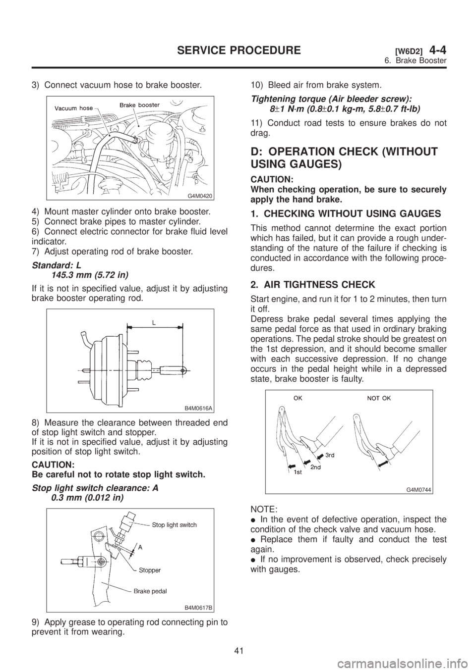
3) Connect vacuum hose to brake booster.
G4M0420
4) Mount master cylinder onto brake booster.
5) Connect brake pipes to master cylinder.
6) Connect electric connector for brake fluid level
indicator.
7) Adjust operating rod of brake booster.
Standard: L
145.3 mm (5.72 in)
If it is not in specified value, adjust it by adjusting
brake booster operating rod.
B4M0616A
8) Measure the clearance between threaded end
of stop light switch and stopper.
If it is not in specified value, adjust it by adjusting
position of stop light switch.
CAUTION:
Be careful not to rotate stop light switch.
Stop light switch clearance: A
0.3 mm (0.012 in)
B4M0617B
9) Apply grease to operating rod connecting pin to
prevent it from wearing.10) Bleed air from brake system.
Tightening torque (Air bleeder screw):
8
±1 N´m (0.8±0.1 kg-m, 5.8±0.7 ft-lb)
11) Conduct road tests to ensure brakes do not
drag.
D: OPERATION CHECK (WITHOUT
USING GAUGES)
CAUTION:
When checking operation, be sure to securely
apply the hand brake.
1. CHECKING WITHOUT USING GAUGES
This method cannot determine the exact portion
which has failed, but it can provide a rough under-
standing of the nature of the failure if checking is
conducted in accordance with the following proce-
dures.
2. AIR TIGHTNESS CHECK
Start engine, and run it for 1 to 2 minutes, then turn
it off.
Depress brake pedal several times applying the
same pedal force as that used in ordinary braking
operations. The pedal stroke should be greatest on
the 1st depression, and it should become smaller
with each successive depression. If no change
occurs in the pedal height while in a depressed
state, brake booster is faulty.
G4M0744
NOTE:
IIn the event of defective operation, inspect the
condition of the check valve and vacuum hose.
IReplace them if faulty and conduct the test
again.
IIf no improvement is observed, check precisely
with gauges.
41
[W6D2]4-4SERVICE PROCEDURE
6. Brake Booster
Page 915 of 1456
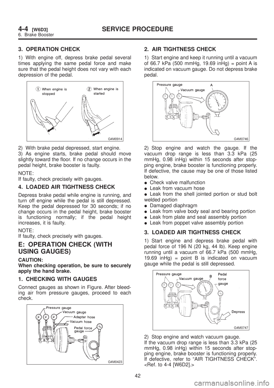
3. OPERATION CHECK
1) With engine off, depress brake pedal several
times applying the same pedal force and make
sure that the pedal height does not vary with each
depression of the pedal.
G4M0914
2) With brake pedal depressed, start engine.
3) As engine starts, brake pedal should move
slightly toward the floor. If no change occurs in the
pedal height, brake booster is faulty.
NOTE:
If faulty, check precisely with gauges.
4. LOADED AIR TIGHTNESS CHECK
Depress brake pedal while engine is running, and
turn off engine while the pedal is still depressed.
Keep the pedal depressed for 30 seconds; if no
change occurs in the pedal height, brake booster
is functioning normally; if the pedal height
increases, it is faulty.
NOTE:
If faulty, check precisely with gauges.
E: OPERATION CHECK (WITH
USING GAUGES)
CAUTION:
When checking operation, be sure to securely
apply the hand brake.
1. CHECKING WITH GAUGES
Connect gauges as shown in Figure. After bleed-
ing air from pressure gauges, proceed to each
check.
G4M0423
2. AIR TIGHTNESS CHECK
1) Start engine and keep it running until a vacuum
of 66.7 kPa (500 mmHg, 19.69 inHg) = point A is
indicated on vacuum gauge. Do not depress brake
pedal.
G4M0746
2) Stop engine and watch the gauge. If the
vacuum drop range is less than 3.3 kPa (25
mmHg, 0.98 inHg) within 15 seconds after stop-
ping engine, brake booster is functioning properly.
If defective, the cause may be one of those listed
below.
ICheck valve malfunction
ILeak from vacuum hose
ILeak from the shell jointed portion or stud bolt
welded portion
IDamaged diaphragm
ILeak from valve body seal and bearing portion
ILeak from plate and seal assembly portion
ILeak from poppet valve assembly portion
3. LOADED AIR TIGHTNESS CHECK
1) Start engine and depress brake pedal with
pedal force of 196 N (20 kg, 44 lb). Keep engine
running until a vacuum of 66.7 kPa (500 mmHg,
19.69 inHg) = point B is indicated on vacuum
gauge while the pedal is still depressed.
G4M0747
2) Stop engine and watch vacuum gauge.
If the vacuum drop range is less than 3.3 kPa (25
mmHg, 0.98 inHg) within 15 seconds after stop-
ping engine, brake booster is functioning properly.
If defective, refer to ªAIR TIGHTNESS CHECKº.
42
4-4[W6D3]SERVICE PROCEDURE
6. Brake Booster
Page 951 of 1456
1. Pedal
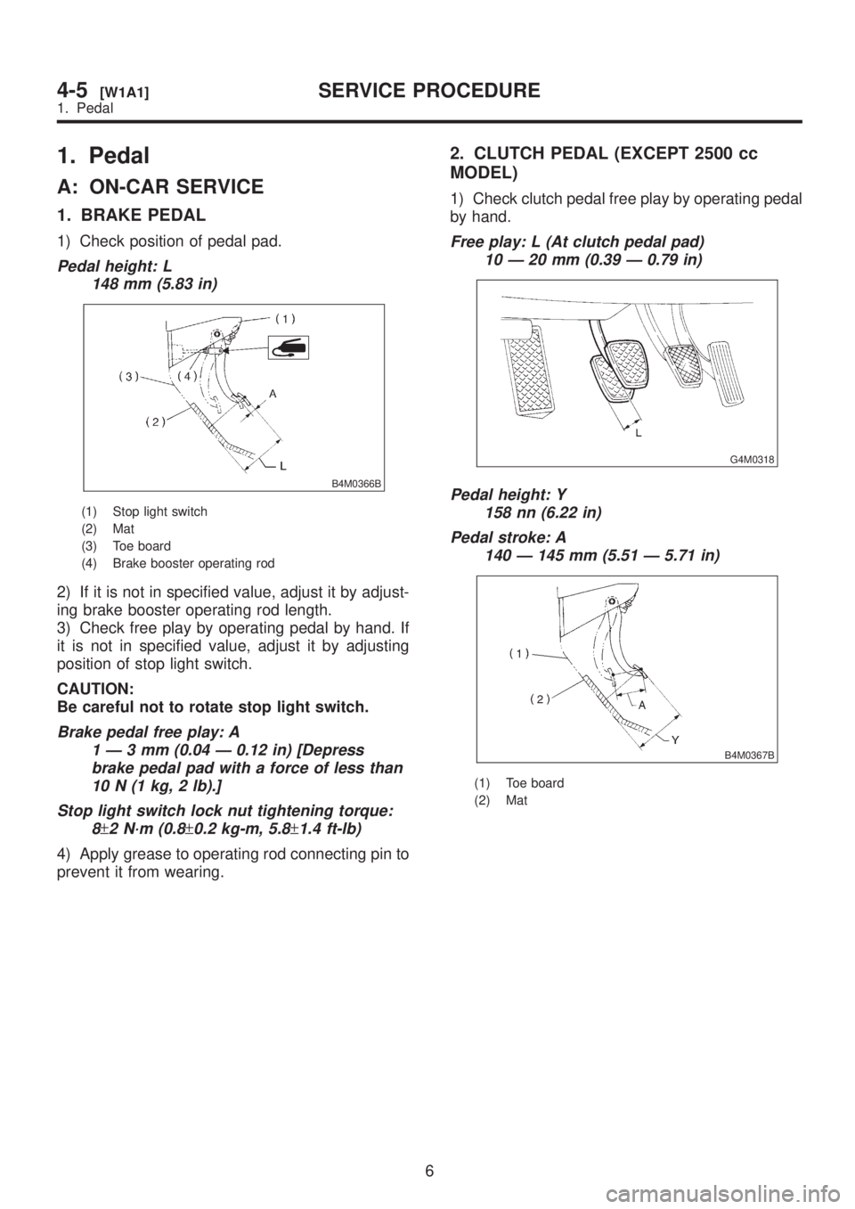
A: ON-CAR SERVICE
1. BRAKE PEDAL
1) Check position of pedal pad.
Pedal height: L
148 mm (5.83 in)
B4M0366B
(1) Stop light switch
(2) Mat
(3) Toe board
(4) Brake booster operating rod
2) If it is not in specified value, adjust it by adjust-
ing brake booster operating rod length.
3) Check free play by operating pedal by hand. If
it is not in specified value, adjust it by adjusting
position of stop light switch.
CAUTION:
Be careful not to rotate stop light switch.
Brake pedal free play: A
1Ð3mm(0.04 Ð 0.12 in) [Depress
brake pedal pad with a force of less than
10 N (1 kg, 2 lb).]
Stop light switch lock nut tightening torque:
8
±2 N´m (0.8±0.2 kg-m, 5.8±1.4 ft-lb)
4) Apply grease to operating rod connecting pin to
prevent it from wearing.
2. CLUTCH PEDAL (EXCEPT 2500 cc
MODEL)
1) Check clutch pedal free play by operating pedal
by hand.
Free play: L (At clutch pedal pad)
10 Ð 20 mm (0.39 Ð 0.79 in)
G4M0318
Pedal height: Y
158 nn (6.22 in)
Pedal stroke: A
140 Ð 145 mm (5.51 Ð 5.71 in)
B4M0367B
(1) Toe board
(2) Mat
6
4-5[W1A1]SERVICE PROCEDURE
1. Pedal
Page 962 of 1456
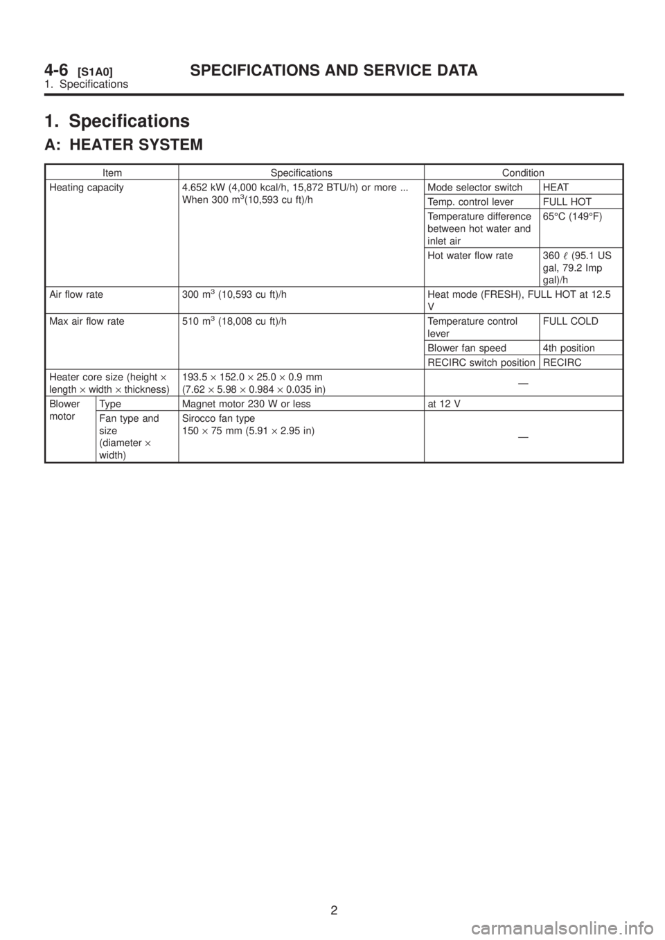
1. Specifications
A: HEATER SYSTEM
Item Specifications Condition
Heating capacity 4.652 kW (4,000 kcal/h, 15,872 BTU/h) or more ...
When 300 m
3(10,593 cu ft)/hMode selector switch HEAT
Temp. control lever FULL HOT
Temperature difference
between hot water and
inlet air65ÉC (149ÉF)
Hot water flow rate 360(95.1 US
gal, 79.2 Imp
gal)/h
Air flow rate 300 m
3(10,593 cu ft)/h Heat mode (FRESH), FULL HOT at 12.5
V
Max air flow rate 510 m
3(18,008 cu ft)/h Temperature control
leverFULL COLD
Blower fan speed 4th position
RECIRC switch position RECIRC
Heater core size (height´
length´width´thickness)193.5´152.0´25.0´0.9 mm
(7.62´5.98´0.984´0.035 in)Ð
Blower
motorType Magnet motor 230 W or less at 12 V
Fan type and
size
(diameter´
width)Sirocco fan type
150´75 mm (5.91´2.95 in)
Ð
2
4-6[S1A0]SPECIFICATIONS AND SERVICE DATA
1. Specifications
Page 1060 of 1456
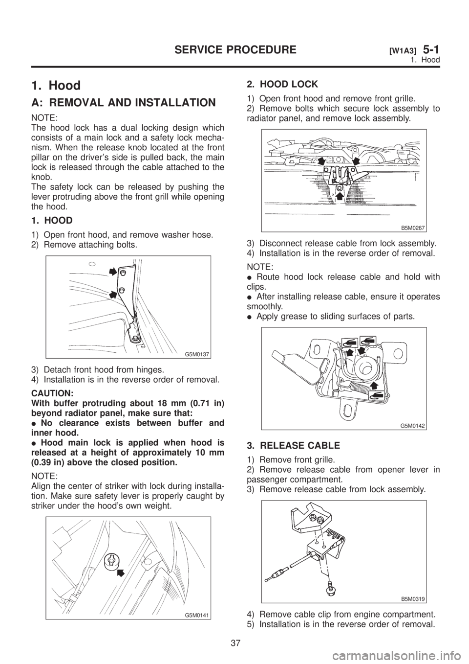
1. Hood
A: REMOVAL AND INSTALLATION
NOTE:
The hood lock has a dual locking design which
consists of a main lock and a safety lock mecha-
nism. When the release knob located at the front
pillar on the driver's side is pulled back, the main
lock is released through the cable attached to the
knob.
The safety lock can be released by pushing the
lever protruding above the front grill while opening
the hood.
1. HOOD
1) Open front hood, and remove washer hose.
2) Remove attaching bolts.
G5M0137
3) Detach front hood from hinges.
4) Installation is in the reverse order of removal.
CAUTION:
With buffer protruding about 18 mm (0.71 in)
beyond radiator panel, make sure that:
INo clearance exists between buffer and
inner hood.
IHood main lock is applied when hood is
released at a height of approximately 10 mm
(0.39 in) above the closed position.
NOTE:
Align the center of striker with lock during installa-
tion. Make sure safety lever is properly caught by
striker under the hood's own weight.
G5M0141
2. HOOD LOCK
1) Open front hood and remove front grille.
2) Remove bolts which secure lock assembly to
radiator panel, and remove lock assembly.
B5M0267
3) Disconnect release cable from lock assembly.
4) Installation is in the reverse order of removal.
NOTE:
IRoute hood lock release cable and hold with
clips.
IAfter installing release cable, ensure it operates
smoothly.
IApply grease to sliding surfaces of parts.
G5M0142
3. RELEASE CABLE
1) Remove front grille.
2) Remove release cable from opener lever in
passenger compartment.
3) Remove release cable from lock assembly.
B5M0319
4) Remove cable clip from engine compartment.
5) Installation is in the reverse order of removal.
37
[W1A3]5-1SERVICE PROCEDURE
1. Hood
Page 1088 of 1456
![SUBARU LEGACY 1999 Service Service Manual 4) Tilt up assembly:
(1) Remove sunroof flame. <Ref. to 5-1
[W16A2].>
(2) Remove tilt up assembly.
B5M0485A
(3) Installation is in the reverse order of
removal.
B: ADJUSTMENT
1. SEDAN AND WAGON REAR (](/img/17/57435/w960_57435-1087.png "SUBARU LEGACY 1999 Service Service Manual 4) Tilt up assembly:
(1) Remove sunroof flame. <Ref. to 5-1
[W16A2].>
(2) Remove tilt up assembly.
B5M0485A
(3) Installation is in the reverse order of
removal.
B: ADJUSTMENT
1. SEDAN AND WAGON REAR (")
4) Tilt up assembly:
(1) Remove sunroof flame.
(2) Remove tilt up assembly.
B5M0485A
(3) Installation is in the reverse order of
removal.
B: ADJUSTMENT
1. SEDAN AND WAGON REAR (EXCEPT
OUTBACK)
1) Alignment of height between glass lid assembly
and roof panel:
(1) Remove guide rail cover.
(2) Loosen nuts and adjust height by adding
(Max: two pieces) and extracting (Max: one
piece) shim(s) (Standard: one piece) between
glass lid assembly and lid bracket.
Difference in height between glass lid assem-
bly and roof panel:
0
±0.5 mm (0±0.020 in)
B5M0314B
B5M0315B
2) Alignment of glass lid assembly with roof panel:
(1) Remove guide rail cover.
(2) Loosen nuts and move glass lid assembly
to either side to adjust front, rear, right, and left
side partitions.
Partition clearance:
7.0
±0.5 mm (0.276±0.020 in)
B5M0316A
3) Checking for movement of glass lid assembly
itself:
(1) Before installing sunroof motor, check glass
lid assembly for movement.
(2) Place a cloth on glass lid assembly and sun
shade, and attach a spring scale to glass lid
assembly edge using the cloth.
B5M0317
(3) Pull spring scale to measure force required
to move glass lid assembly.
Force required to move glass lid assembly
and sun shade trim:
Less than 196 N (20 kg, 44 lb)
Considerable effort is required to start glass lid
assembly moving, so take scale reading while
glass lid assembly is moving smoothly.
(4) If force required exceeds specifications,
check the following points:
IGlass lid assembly, sun shade and deflector and
guide rail assembly for improper installation
ICable for seizure
60
5-1[W16B1]SERVICE PROCEDURE
16. Sunroof
Page 1089 of 1456
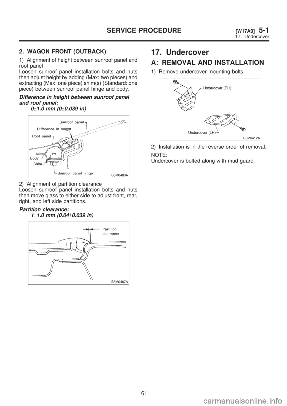
2. WAGON FRONT (OUTBACK)
1) Alignment of height between sunroof panel and
roof panel
Loosen sunroof panel installation bolts and nuts
then adjust height by adding (Max: two pieces) and
extracting (Max: one piece) shim(s) (Standard: one
piece) between sunroof panel hinge and body.
Difference in height between sunroof panel
and roof panel:
0
±1.0 mm (0±0.039 in)
B5M0486A
2) Alignment of partition clearance
Loosen sunroof panel installation bolts and nuts
then move glass to either side to adjust front, rear,
right, and left side partitions.
Partition clearance:
1
±1.0 mm (0.04±0.039 in)
B5M0487A
17. Undercover
A: REMOVAL AND INSTALLATION
1) Remove undercover mounting bolts.
B5M0412A
2) Installation is in the reverse order of removal.
NOTE:
Undercover is bolted along with mud guard.
61
[W17A0]5-1SERVICE PROCEDURE
17. Undercover