height SUBARU LEGACY 1999 Service Owner's Guide
[x] Cancel search | Manufacturer: SUBARU, Model Year: 1999, Model line: LEGACY, Model: SUBARU LEGACY 1999Pages: 1456, PDF Size: 59.93 MB
Page 690 of 1456
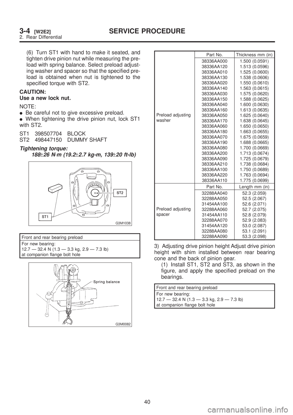
(6) Turn ST1 with hand to make it seated, and
tighten drive pinion nut while measuring the pre-
load with spring balance. Select preload adjust-
ing washer and spacer so that the specified pre-
load is obtained when nut is tightened to the
specified torque with ST2.
CAUTION:
Use a new lock nut.
NOTE:
IBe careful not to give excessive preload.
IWhen tightening the drive pinion nut, lock ST1
with ST2.
ST1 398507704 BLOCK
ST2 498447150 DUMMY SHAFT
Tightening torque:
188
±26 N´m (19.2±2.7 kg-m, 139±20 ft-lb)
G3M1038
Front and rear bearing preload
For new bearing:
12.7 Ð 32.4 N (1.3 Ð 3.3 kg, 2.9 Ð 7.3 lb)
at companion flange bolt hole
G3M0082
Preload adjusting
washerPart No. Thickness mm (in)
38336AA000
38336AA120
38336AA010
38336AA130
38336AA020
38336AA140
38336AA030
38336AA150
38336AA040
38336AA160
38336AA050
38336AA170
38336AA060
38336AA180
38336AA070
38336AA190
38336AA080
38336AA200
38336AA090
38336AA210
38336AA100
38336AA220
38336AA1101.500 (0.0591)
1.513 (0.0596)
1.525 (0.0600)
1.538 (0.0606)
1.550 (0.0610)
1.563 (0.0615)
1.575 (0.0620)
1.588 (0.0625)
1.600 (0.0630)
1.613 (0.0635)
1.625 (0.0640)
1.638 (0.0645)
1.650 (0.0650)
1.663 (0.0655)
1.675 (0.0659)
1.688 (0.0665)
1.700 (0.0669)
1.713 (0.0674)
1.725 (0.0679)
1.738 (0.0684)
1.750 (0.0689)
1.763 (0.0694)
1.775 (0.0699)
Preload adjusting
spacerPart No. Length mm (in)
32288AA040
32288AA050
31454AA100
32288AA060
31454AA110
32288AA070
31454AA120
32288AA080
32288AA09052.3 (2.059)
52.5 (2.067)
52.6 (2.071)
52.7 (2.075)
52.8 (2.079)
52.9 (2.083)
53.0 (2.087)
53.1 (2.091)
53.3 (2.098)
3) Adjusting drive pinion height Adjust drive pinion
height with shim installed between rear bearing
cone and the back of pinion gear.
(1) Install ST1, ST2 and ST3, as shown in the
figure, and apply the specified preload on the
bearings.
Front and rear bearing preload
For new bearing:
12.7 Ð 32.4 N (1.3 Ð 3.3 kg, 2.9 Ð 7.3 lb)
at companion flange bolt hole
40
3-4[W2E2]SERVICE PROCEDURE
2. Rear Differential
Page 691 of 1456
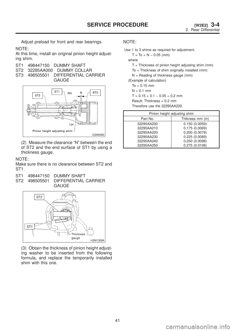
Adjust preload for front and rear bearings.
NOTE:
At this time, install an original pinion height adjust-
ing shim.
ST1 498447150 DUMMY SHAFT
ST2 32285AA000 DUMMY COLLAR
ST3 498505501 DIFFERENTIAL CARRIER
GAUGE
G3M0083
(2) Measure the clearance ªNº between the end
of ST2 and the end surface of ST1 by using a
thickness gauge.
NOTE:
Make sure there is no clearance between ST2 and
ST1.
ST1 498447150 DUMMY SHAFT
ST2 498505501 DIFFERENTIAL CARRIER
GAUGE
H3M1309A
(3) Obtain the thickness of pinion height adjust-
ing washer to be inserted from the following
formula, and replace the temporarily installed
shim with this one.NOTE:
Use 1 to 3 shims as required for adjustment.
T=To+Nþ0.05 (mm)
where
T = Thickness of pinion height adjusting shim (mm)
To = Thickness of shim originally installed (mm)
N = Reading of thickness gauge (mm)
(Example of calculation)
To = 0.15 mm
N = 0.1 mm
T = 0.15 + 0.1 þ 0.05 = 0.2 mm
Result: Thickness = 0.2 mm
Therefore use the 32295AA220.
Pinion height adjusting shim
Part No. Thikness mm (in)
32295AA200
32295AA210
32295AA220
32295AA230
32295AA240
32295AA2500.150 (0.0059)
0.175 (0.0069)
0.200 (0.0079)
0.225 (0.0089)
0.250 (0.0098)
0.275 (0.0108)
41
[W2E2]3-4SERVICE PROCEDURE
2. Rear Differential
Page 692 of 1456
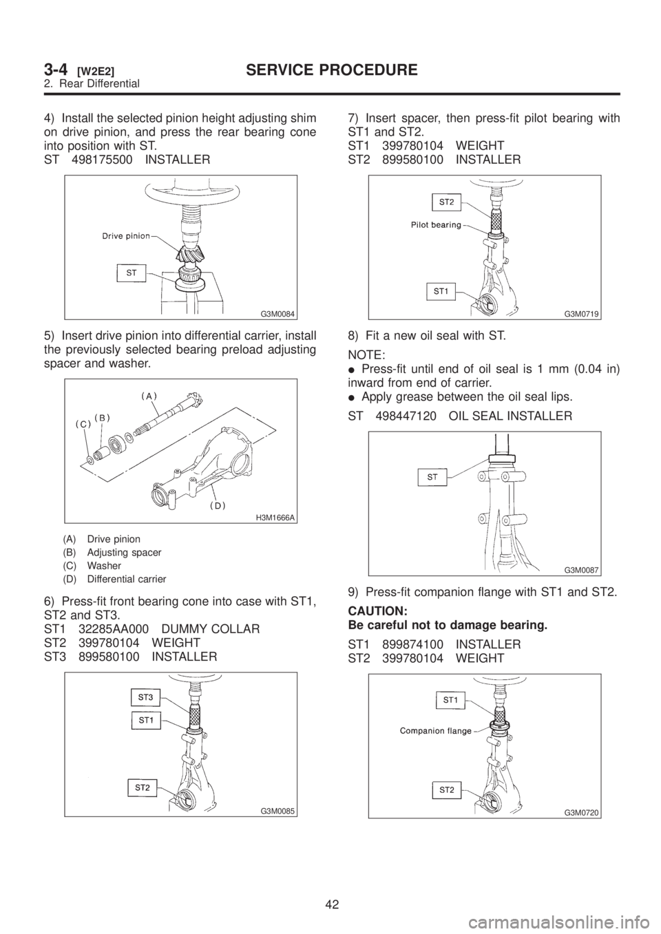
4) Install the selected pinion height adjusting shim
on drive pinion, and press the rear bearing cone
into position with ST.
ST 498175500 INSTALLER
G3M0084
5) Insert drive pinion into differential carrier, install
the previously selected bearing preload adjusting
spacer and washer.
H3M1666A
(A) Drive pinion
(B) Adjusting spacer
(C) Washer
(D) Differential carrier
6) Press-fit front bearing cone into case with ST1,
ST2 and ST3.
ST1 32285AA000 DUMMY COLLAR
ST2 399780104 WEIGHT
ST3 899580100 INSTALLER
G3M0085
7) Insert spacer, then press-fit pilot bearing with
ST1 and ST2.
ST1 399780104 WEIGHT
ST2 899580100 INSTALLER
G3M0719
8) Fit a new oil seal with ST.
NOTE:
IPress-fit until end of oil seal is 1 mm (0.04 in)
inward from end of carrier.
IApply grease between the oil seal lips.
ST 498447120 OIL SEAL INSTALLER
G3M0087
9) Press-fit companion flange with ST1 and ST2.
CAUTION:
Be careful not to damage bearing.
ST1 899874100 INSTALLER
ST2 399780104 WEIGHT
G3M0720
42
3-4[W2E2]SERVICE PROCEDURE
2. Rear Differential
Page 695 of 1456
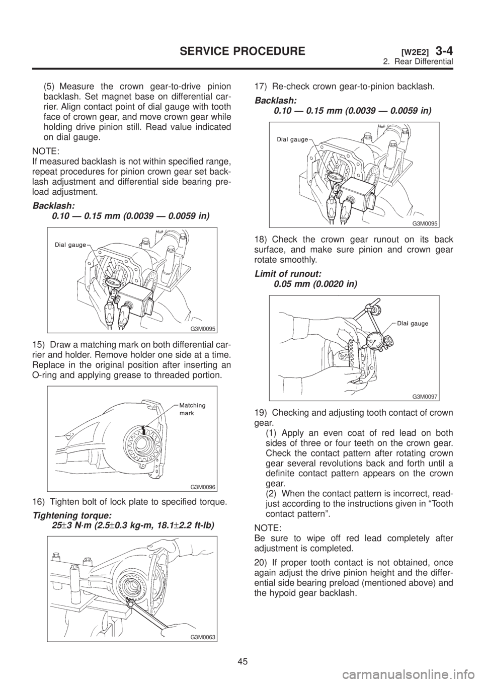
(5) Measure the crown gear-to-drive pinion
backlash. Set magnet base on differential car-
rier. Align contact point of dial gauge with tooth
face of crown gear, and move crown gear while
holding drive pinion still. Read value indicated
on dial gauge.
NOTE:
If measured backlash is not within specified range,
repeat procedures for pinion crown gear set back-
lash adjustment and differential side bearing pre-
load adjustment.
Backlash:
0.10 Ð 0.15 mm (0.0039 Ð 0.0059 in)
G3M0095
15) Draw a matching mark on both differential car-
rier and holder. Remove holder one side at a time.
Replace in the original position after inserting an
O-ring and applying grease to threaded portion.
G3M0096
16) Tighten bolt of lock plate to specified torque.
Tightening torque:
25
±3 N´m (2.5±0.3 kg-m, 18.1±2.2 ft-lb)
G3M0063
17) Re-check crown gear-to-pinion backlash.
Backlash:
0.10 Ð 0.15 mm (0.0039 Ð 0.0059 in)
G3M0095
18) Check the crown gear runout on its back
surface, and make sure pinion and crown gear
rotate smoothly.
Limit of runout:
0.05 mm (0.0020 in)
G3M0097
19) Checking and adjusting tooth contact of crown
gear.
(1) Apply an even coat of red lead on both
sides of three or four teeth on the crown gear.
Check the contact pattern after rotating crown
gear several revolutions back and forth until a
definite contact pattern appears on the crown
gear.
(2) When the contact pattern is incorrect, read-
just according to the instructions given in ªTooth
contact patternº.
NOTE:
Be sure to wipe off red lead completely after
adjustment is completed.
20) If proper tooth contact is not obtained, once
again adjust the drive pinion height and the differ-
ential side bearing preload (mentioned above) and
the hypoid gear backlash.
45
[W2E2]3-4SERVICE PROCEDURE
2. Rear Differential
Page 696 of 1456
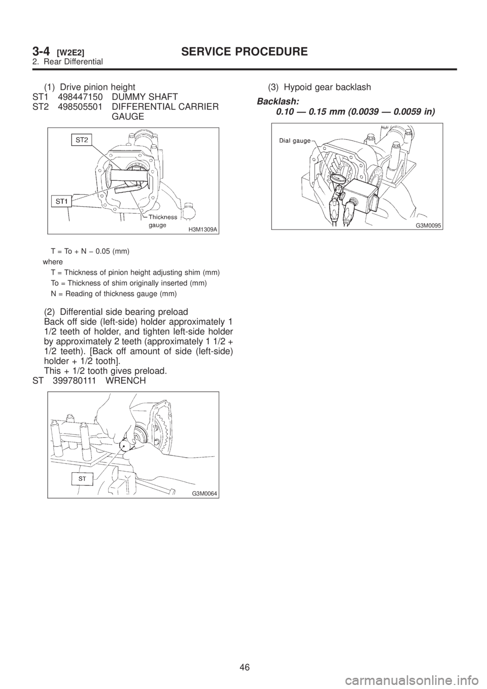
(1) Drive pinion height
ST1 498447150 DUMMY SHAFT
ST2 498505501 DIFFERENTIAL CARRIER
GAUGE
H3M1309A
T=To+Nþ0.05 (mm)
where
T = Thickness of pinion height adjusting shim (mm)
To = Thickness of shim originally inserted (mm)
N = Reading of thickness gauge (mm)
(2) Differential side bearing preload
Back off side (left-side) holder approximately 1
1/2 teeth of holder, and tighten left-side holder
by approximately 2 teeth (approximately 1 1/2 +
1/2 teeth). [Back off amount of side (left-side)
holder + 1/2 tooth].
This + 1/2 tooth gives preload.
ST 399780111 WRENCH
G3M0064
(3) Hypoid gear backlash
Backlash:
0.10 Ð 0.15 mm (0.0039 Ð 0.0059 in)
G3M0095
46
3-4[W2E2]SERVICE PROCEDURE
2. Rear Differential
Page 697 of 1456
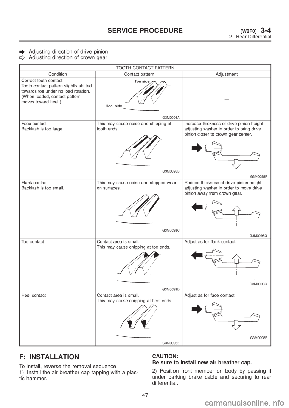
Adjusting direction of drive pinion
Adjusting direction of crown gear
TOOTH CONTACT PATTERN
Condition Contact pattern Adjustment
Correct tooth contact
Tooth contact pattern slightly shifted
towards toe under no load rotation.
(When loaded, contact pattern
moves toward heel.)
G3M0098A
Ð
Face contact
Backlash is too large.This may cause noise and chipping at
tooth ends.
G3M0098B
Increase thickness of drive pinion height
adjusting washer in order to bring drive
pinion closer to crown gear center.
G3M0098F
Flank contact
Backlash is too small.This may cause noise and stepped wear
on surfaces.
G3M0098C
Reduce thickness of drive pinion height
adjusting washer in order to move drive
pinion away from crown gear.
G3M0098G
Toe contact Contact area is small.
This may cause chipping at toe ends.
G3M0098D
Adjust as for flank contact.
G3M0098G
Heel contact Contact area is small.
This may cause chipping at heel ends.
G3M0098E
Adjust as for face contact
G3M0098F
F: INSTALLATION
To install, reverse the removal sequence.
1) Install the air breather cap tapping with a plas-
tic hammer.CAUTION:
Be sure to install new air breather cap.
2) Position front member on body by passing it
under parking brake cable and securing to rear
differential.
47
[W2F0]3-4SERVICE PROCEDURE
2. Rear Differential
Page 705 of 1456
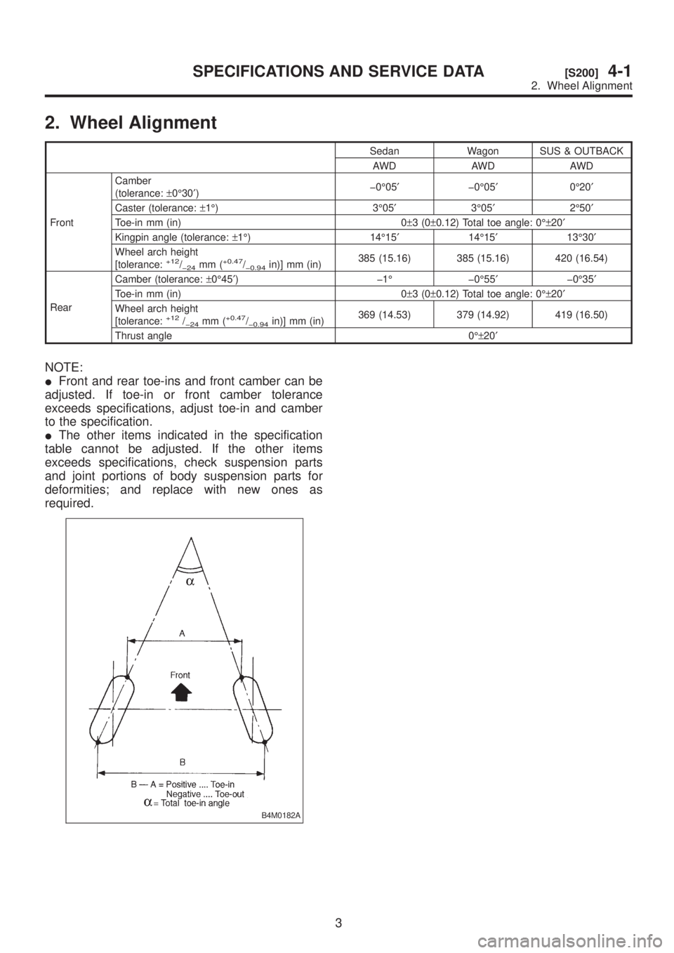
2. Wheel Alignment
Sedan Wagon SUS & OUTBACK
AWD AWD AWD
FrontCamber
(tolerance:±0É30¢)þ0É05¢þ0É05¢0É20¢
Caster (tolerance:±1É) 3É05¢3É05¢2É50¢
Toe-in mm (in) 0±3(0±0.12) Total toe angle: 0ɱ20¢
Kingpin angle (tolerance:±1É) 14É15¢14É15¢13É30¢
Wheel arch height
[tolerance:
+12/þ24mm (+0.47/þ0.94in)] mm (in)385 (15.16) 385 (15.16) 420 (16.54)
RearCamber (tolerance:±0É45¢) þ1É þ0É55¢þ0É35¢
Toe-in mm (in) 0±3(0±0.12) Total toe angle: 0ɱ20¢
Wheel arch height
[tolerance:
+12/þ24mm (+0.47/þ0.94in)] mm (in)369 (14.53) 379 (14.92) 419 (16.50)
Thrust angle 0ɱ20¢
NOTE:
IFront and rear toe-ins and front camber can be
adjusted. If toe-in or front camber tolerance
exceeds specifications, adjust toe-in and camber
to the specification.
IThe other items indicated in the specification
table cannot be adjusted. If the other items
exceeds specifications, check suspension parts
and joint portions of body suspension parts for
deformities; and replace with new ones as
required.
B4M0182A
3
[S200]4-1SPECIFICATIONS AND SERVICE DATA
2. Wheel Alignment
Page 710 of 1456
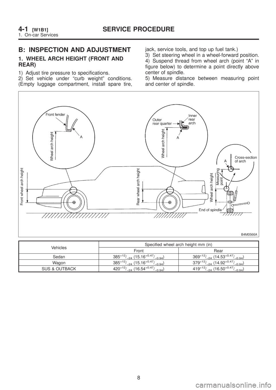
B: INSPECTION AND ADJUSTMENT
1. WHEEL ARCH HEIGHT (FRONT AND
REAR)
1) Adjust tire pressure to specifications.
2) Set vehicle under ªcurb weightº conditions.
(Empty luggage compartment, install spare tire,jack, service tools, and top up fuel tank.)
3) Set steering wheel in a wheel-forward position.
4) Suspend thread from wheel arch (point ªAº in
figure below) to determine a point directly above
center of spindle.
5) Measure distance between measuring point
and center of spindle.
B4M0566A
VehiclesSpecified wheel arch height mm (in)
Front Rear
Sedan 385
+12/þ24(15.16+0.47/þ0.94) 369+12/þ24(14.53+0.47/þ0.94)
Wagon 385+12/þ24(15.16+0.47/þ0.94) 379+12/þ24(14.92+0.47/þ0.94)
SUS & OUTBACK 420+12/þ24(16.54+0.47/þ0.94) 419+12/þ24(16.50+0.47/þ0.94)
8
4-1[W1B1]SERVICE PROCEDURE
1. On-car Services
Page 711 of 1456
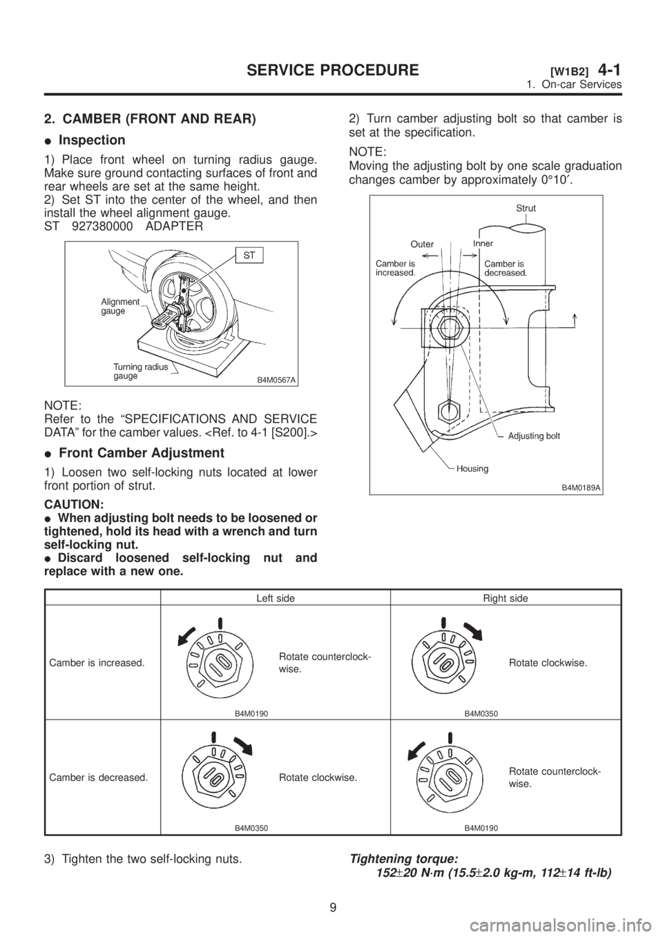
2. CAMBER (FRONT AND REAR)
IInspection
1) Place front wheel on turning radius gauge.
Make sure ground contacting surfaces of front and
rear wheels are set at the same height.
2) Set ST into the center of the wheel, and then
install the wheel alignment gauge.
ST 927380000 ADAPTER
B4M0567A
NOTE:
Refer to the ªSPECIFICATIONS AND SERVICE
DATAº for the camber values.
IFront Camber Adjustment
1) Loosen two self-locking nuts located at lower
front portion of strut.
CAUTION:
IWhen adjusting bolt needs to be loosened or
tightened, hold its head with a wrench and turn
self-locking nut.
IDiscard loosened self-locking nut and
replace with a new one.2) Turn camber adjusting bolt so that camber is
set at the specification.
NOTE:
Moving the adjusting bolt by one scale graduation
changes camber by approximately 0É10¢.
B4M0189A
Left side Right side
Camber is increased.
B4M0190
Rotate counterclock-
wise.
B4M0350
Rotate clockwise.
Camber is decreased.
B4M0350
Rotate clockwise.
B4M0190
Rotate counterclock-
wise.
3) Tighten the two self-locking nuts.Tightening torque:
152
±20 N´m (15.5±2.0 kg-m, 112±14 ft-lb)
9
[W1B2]4-1SERVICE PROCEDURE
1. On-car Services
Page 712 of 1456
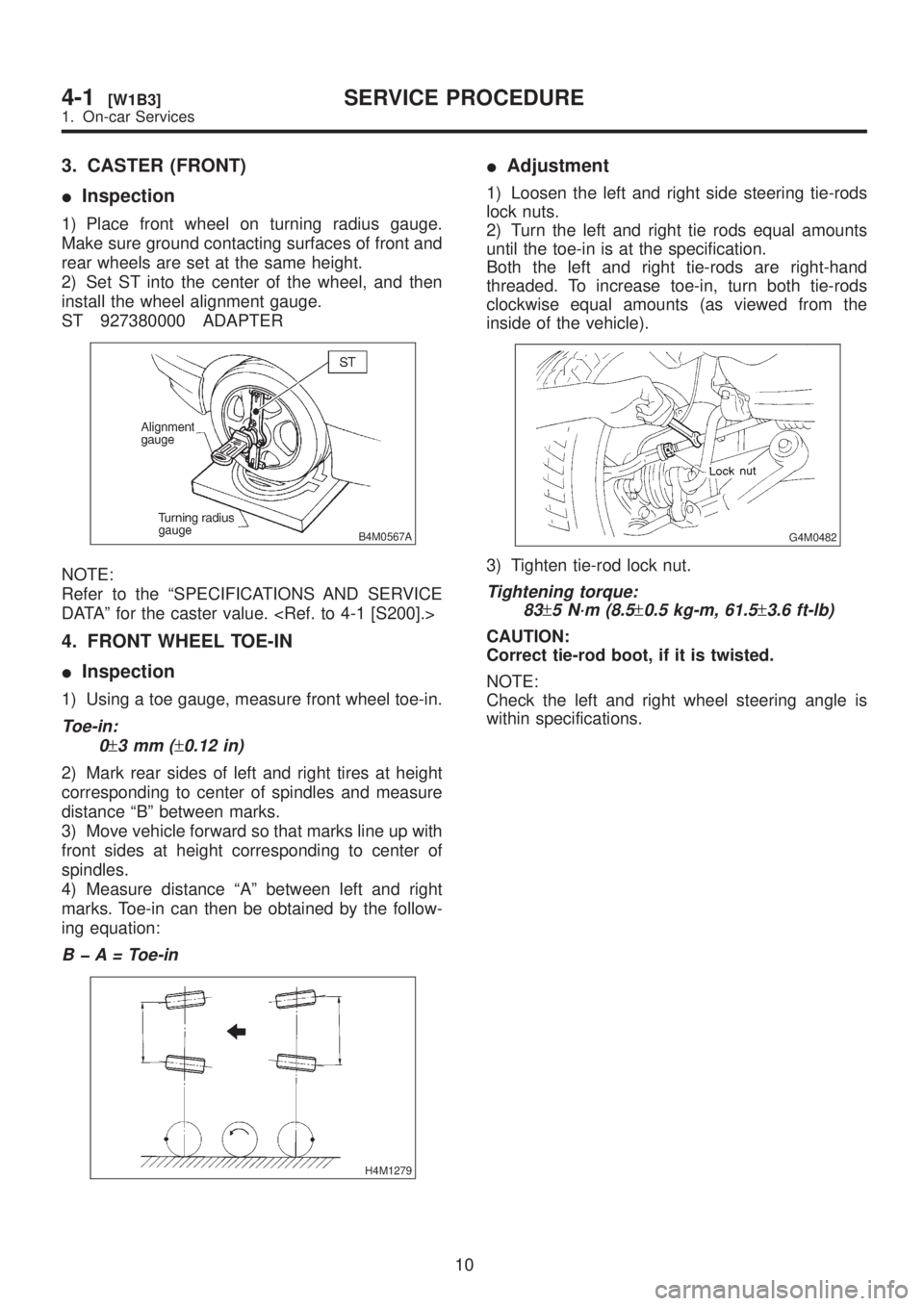
3. CASTER (FRONT)
IInspection
1) Place front wheel on turning radius gauge.
Make sure ground contacting surfaces of front and
rear wheels are set at the same height.
2) Set ST into the center of the wheel, and then
install the wheel alignment gauge.
ST 927380000 ADAPTER
B4M0567A
NOTE:
Refer to the ªSPECIFICATIONS AND SERVICE
DATAº for the caster value.
4. FRONT WHEEL TOE-IN
IInspection
1) Using a toe gauge, measure front wheel toe-in.
Toe-in:
0
±3mm(±0.12 in)
2) Mark rear sides of left and right tires at height
corresponding to center of spindles and measure
distance ªBº between marks.
3) Move vehicle forward so that marks line up with
front sides at height corresponding to center of
spindles.
4) Measure distance ªAº between left and right
marks. Toe-in can then be obtained by the follow-
ing equation:
B þ A = Toe-in
H4M1279
IAdjustment
1) Loosen the left and right side steering tie-rods
lock nuts.
2) Turn the left and right tie rods equal amounts
until the toe-in is at the specification.
Both the left and right tie-rods are right-hand
threaded. To increase toe-in, turn both tie-rods
clockwise equal amounts (as viewed from the
inside of the vehicle).
G4M0482
3) Tighten tie-rod lock nut.
Tightening torque:
83
±5 N´m (8.5±0.5 kg-m, 61.5±3.6 ft-lb)
CAUTION:
Correct tie-rod boot, if it is twisted.
NOTE:
Check the left and right wheel steering angle is
within specifications.
10
4-1[W1B3]SERVICE PROCEDURE
1. On-car Services