engine coolant SUBARU LEGACY 1999 Service Owner's Guide
[x] Cancel search | Manufacturer: SUBARU, Model Year: 1999, Model line: LEGACY, Model: SUBARU LEGACY 1999Pages: 1456, PDF Size: 59.93 MB
Page 296 of 1456
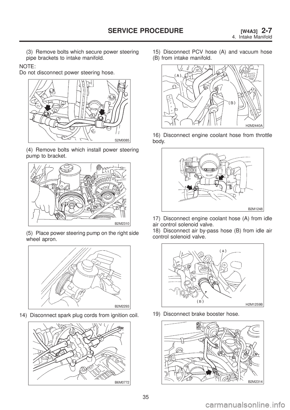
(3) Remove bolts which secure power steering
pipe brackets to intake manifold.
NOTE:
Do not disconnect power steering hose.
S2M0085
(4) Remove bolts which install power steering
pump to bracket.
B2M2310
(5) Place power steering pump on the right side
wheel apron.
B2M2293
14) Disconnect spark plug cords from ignition coil.
B6M0772
15) Disconnect PCV hose (A) and vacuum hose
(B) from intake manifold.
H2M2440A
16) Disconnect engine coolant hose from throttle
body.
B2M1248
17) Disconnect engine coolant hose (A) from idle
air control solenoid valve.
18) Disconnect air by-pass hose (B) from idle air
control solenoid valve.
H2M1259B
19) Disconnect brake booster hose.
B2M2314
35
[W4A3]2-7SERVICE PROCEDURE
4. Intake Manifold
Page 297 of 1456
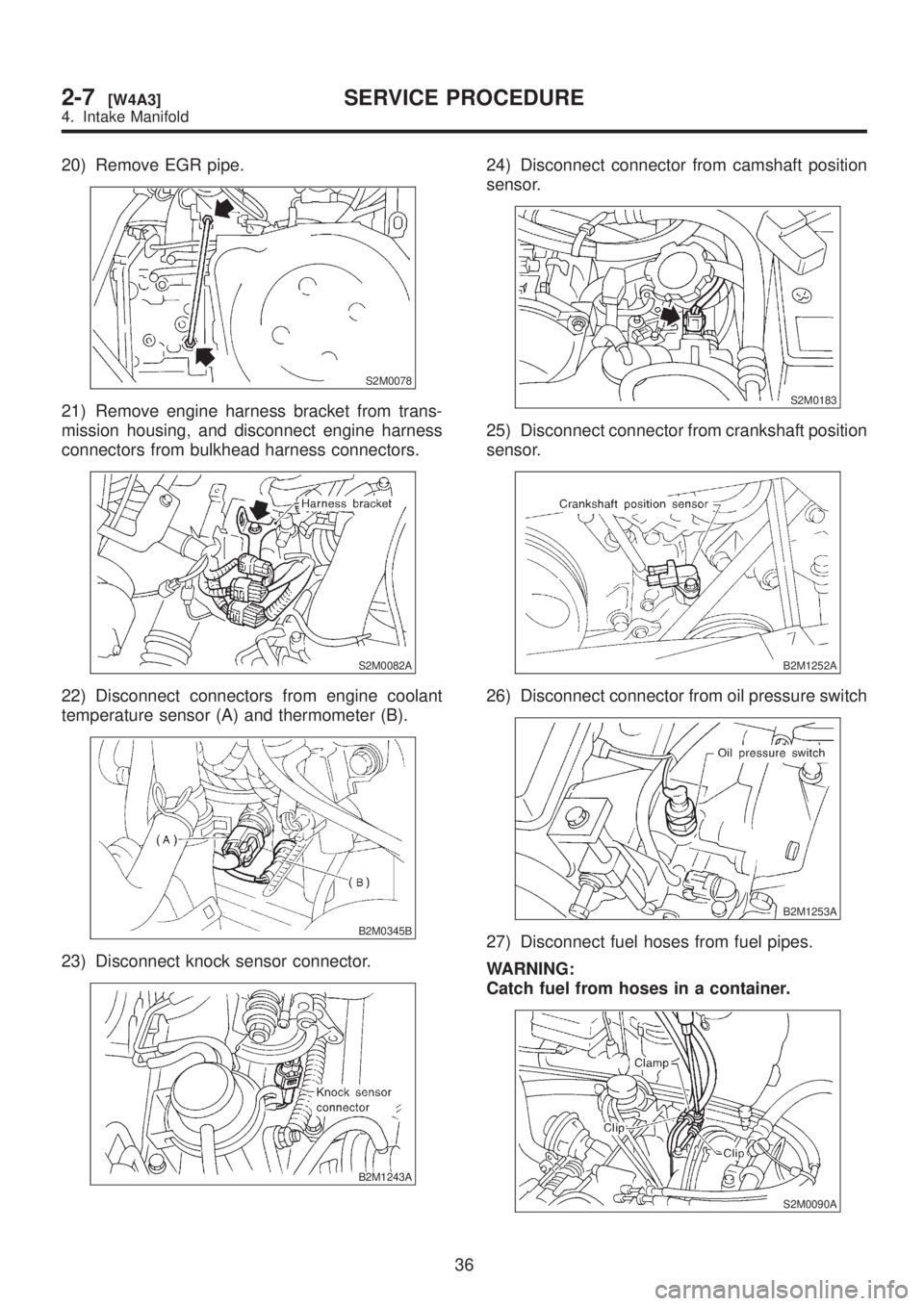
20) Remove EGR pipe.
S2M0078
21) Remove engine harness bracket from trans-
mission housing, and disconnect engine harness
connectors from bulkhead harness connectors.
S2M0082A
22) Disconnect connectors from engine coolant
temperature sensor (A) and thermometer (B).
B2M0345B
23) Disconnect knock sensor connector.
B2M1243A
24) Disconnect connector from camshaft position
sensor.
S2M0183
25) Disconnect connector from crankshaft position
sensor.
B2M1252A
26) Disconnect connector from oil pressure switch
B2M1253A
27) Disconnect fuel hoses from fuel pipes.
WARNING:
Catch fuel from hoses in a container.
S2M0090A
36
2-7[W4A3]SERVICE PROCEDURE
4. Intake Manifold
Page 310 of 1456
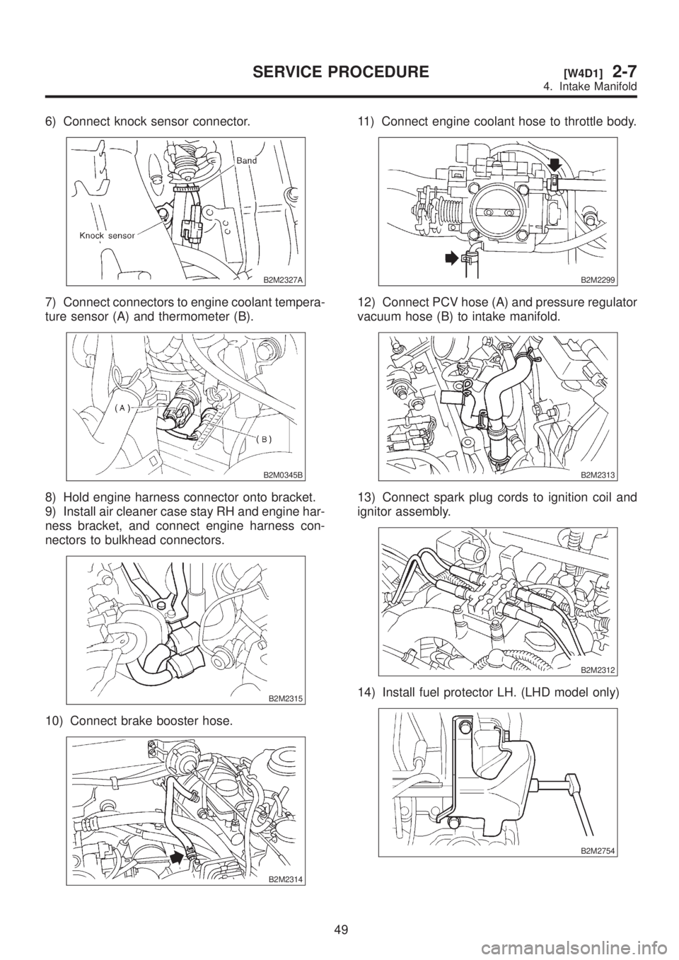
6) Connect knock sensor connector.
B2M2327A
7) Connect connectors to engine coolant tempera-
ture sensor (A) and thermometer (B).
B2M0345B
8) Hold engine harness connector onto bracket.
9) Install air cleaner case stay RH and engine har-
ness bracket, and connect engine harness con-
nectors to bulkhead connectors.
B2M2315
10) Connect brake booster hose.
B2M2314
11) Connect engine coolant hose to throttle body.
B2M2299
12) Connect PCV hose (A) and pressure regulator
vacuum hose (B) to intake manifold.
B2M2313
13) Connect spark plug cords to ignition coil and
ignitor assembly.
B2M2312
14) Install fuel protector LH. (LHD model only)
B2M2754
49
[W4D1]2-7SERVICE PROCEDURE
4. Intake Manifold
Page 314 of 1456
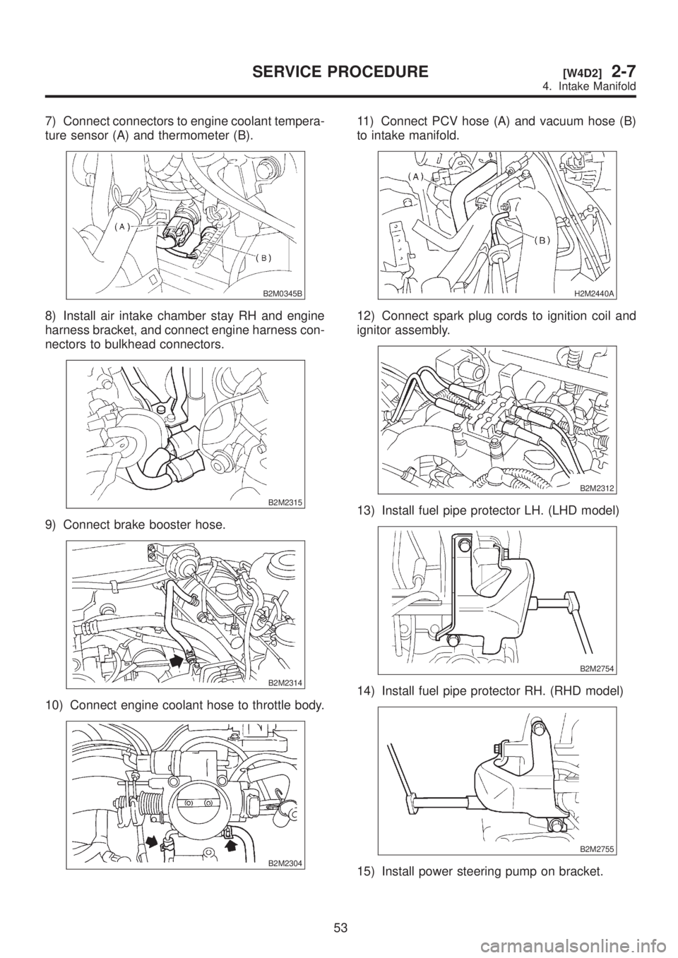
7) Connect connectors to engine coolant tempera-
ture sensor (A) and thermometer (B).
B2M0345B
8) Install air intake chamber stay RH and engine
harness bracket, and connect engine harness con-
nectors to bulkhead connectors.
B2M2315
9) Connect brake booster hose.
B2M2314
10) Connect engine coolant hose to throttle body.
B2M2304
11) Connect PCV hose (A) and vacuum hose (B)
to intake manifold.
H2M2440A
12) Connect spark plug cords to ignition coil and
ignitor assembly.
B2M2312
13) Install fuel pipe protector LH. (LHD model)
B2M2754
14) Install fuel pipe protector RH. (RHD model)
B2M2755
15) Install power steering pump on bracket.
53
[W4D2]2-7SERVICE PROCEDURE
4. Intake Manifold
Page 317 of 1456
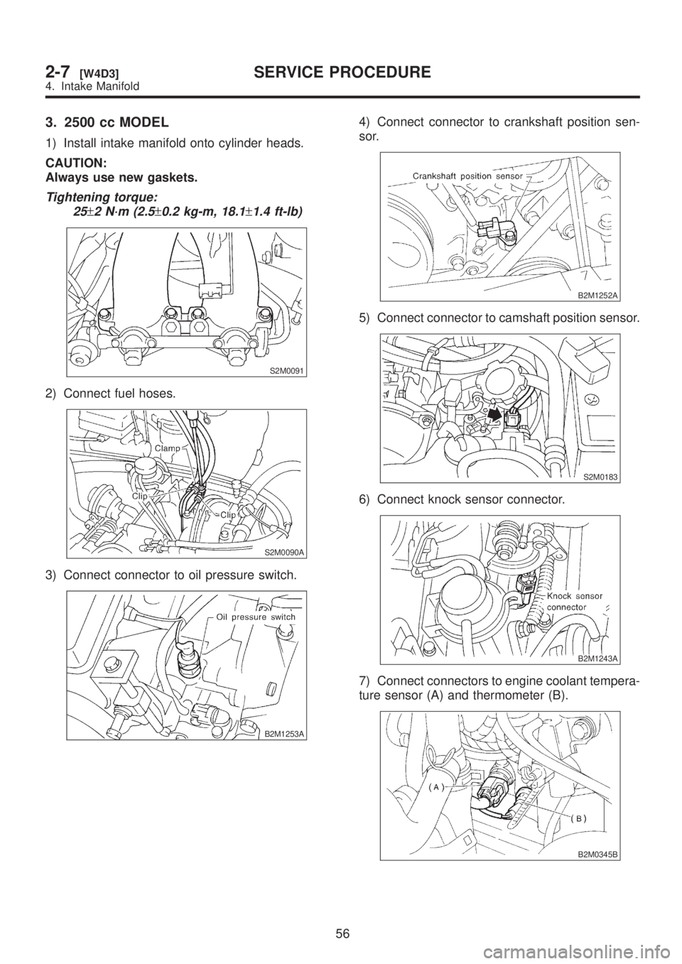
3. 2500 cc MODEL
1) Install intake manifold onto cylinder heads.
CAUTION:
Always use new gaskets.
Tightening torque:
25
±2 N´m (2.5±0.2 kg-m, 18.1±1.4 ft-lb)
S2M0091
2) Connect fuel hoses.
S2M0090A
3) Connect connector to oil pressure switch.
B2M1253A
4) Connect connector to crankshaft position sen-
sor.
B2M1252A
5) Connect connector to camshaft position sensor.
S2M0183
6) Connect knock sensor connector.
B2M1243A
7) Connect connectors to engine coolant tempera-
ture sensor (A) and thermometer (B).
B2M0345B
56
2-7[W4D3]SERVICE PROCEDURE
4. Intake Manifold
Page 318 of 1456
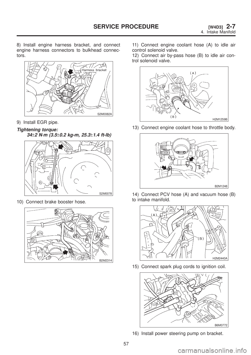
8) Install engine harness bracket, and connect
engine harness connectors to bulkhead connec-
tors.
S2M0082A
9) Install EGR pipe.
Tightening torque:
34
±2 N´m (3.5±0.2 kg-m, 25.3±1.4 ft-lb)
S2M0078
10) Connect brake booster hose.
B2M2314
11) Connect engine coolant hose (A) to idle air
control solenoid valve.
12) Connect air by-pass hose (B) to idle air con-
trol solenoid valve.
H2M1259B
13) Connect engine coolant hose to throttle body.
B2M1248
14) Connect PCV hose (A) and vacuum hose (B)
to intake manifold.
H2M2440A
15) Connect spark plug cords to ignition coil.
B6M0772
16) Install power steering pump on bracket.
57
[W4D3]2-7SERVICE PROCEDURE
4. Intake Manifold
Page 321 of 1456
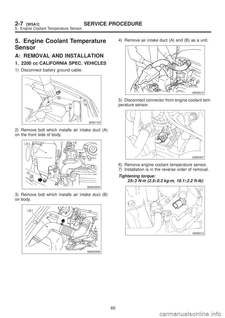
5. Engine Coolant Temperature
Sensor
A: REMOVAL AND INSTALLATION
1. 2200 cc CALIFORNIA SPEC. VEHICLES
1) Disconnect battery ground cable.
B2M1723
2) Remove bolt which installs air intake duct (A)
on the front side of body.
B2M2283A
3) Remove bolt which installs air intake duct (B)
on body.
B2M2284A
4) Remove air intake duct (A) and (B) as a unit.
B2M2012
5) Disconnect connector from engine coolant tem-
perature sensor.
G2M0407
6) Remove engine coolant temperature sensor.
7) Installation is in the reverse order of removal.
Tightening torque:
25
±3 N´m (2.5±0.3 kg-m, 18.1±2.2 ft-lb)
S2M0513
60
2-7[W5A1]SERVICE PROCEDURE
5. Engine Coolant Temperature Sensor
Page 322 of 1456
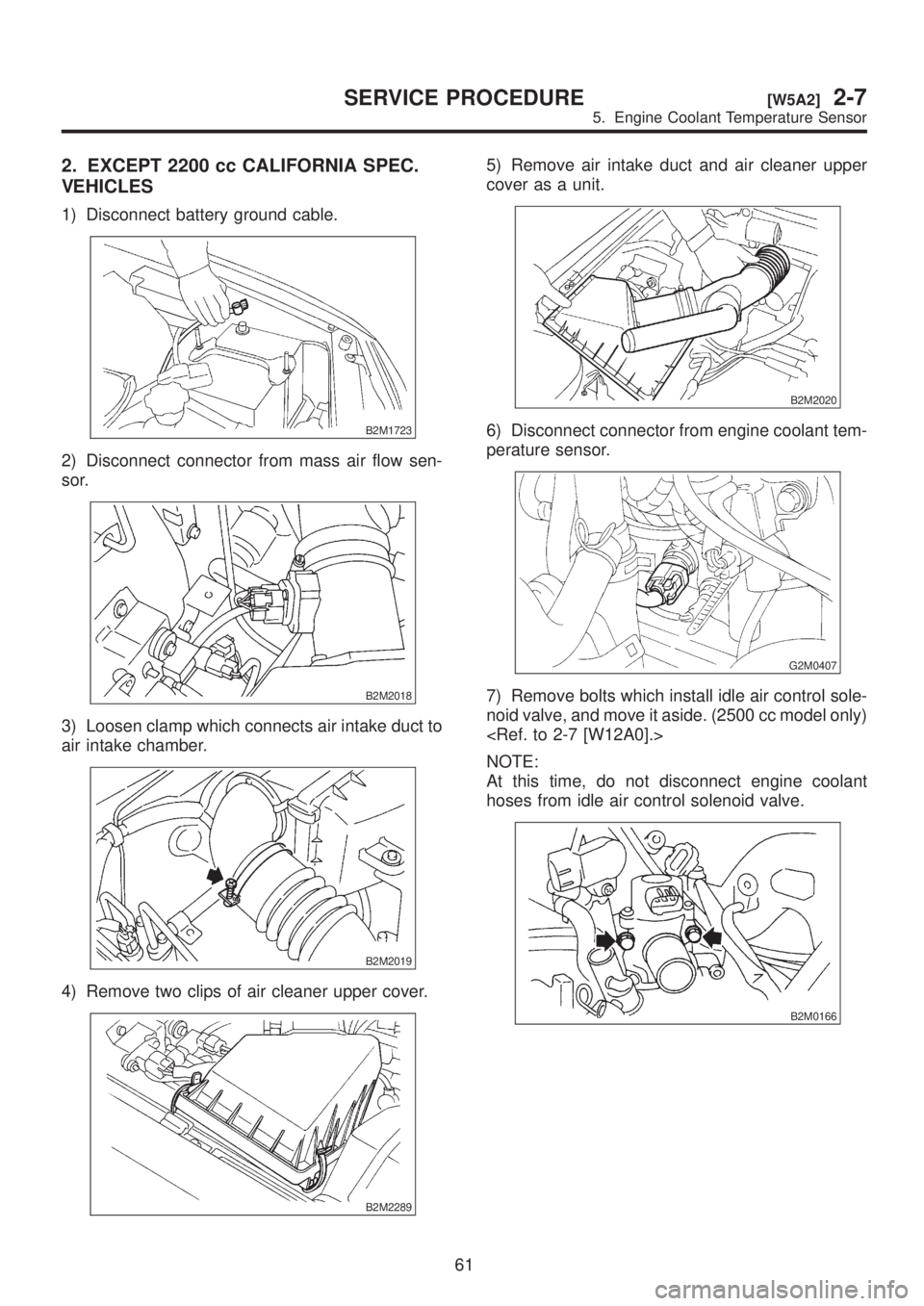
2. EXCEPT 2200 cc CALIFORNIA SPEC.
VEHICLES
1) Disconnect battery ground cable.
B2M1723
2) Disconnect connector from mass air flow sen-
sor.
B2M2018
3) Loosen clamp which connects air intake duct to
air intake chamber.
B2M2019
4) Remove two clips of air cleaner upper cover.
B2M2289
5) Remove air intake duct and air cleaner upper
cover as a unit.
B2M2020
6) Disconnect connector from engine coolant tem-
perature sensor.
G2M0407
7) Remove bolts which install idle air control sole-
noid valve, and move it aside. (2500 cc model only)
NOTE:
At this time, do not disconnect engine coolant
hoses from idle air control solenoid valve.
B2M0166
61
[W5A2]2-7SERVICE PROCEDURE
5. Engine Coolant Temperature Sensor
Page 323 of 1456
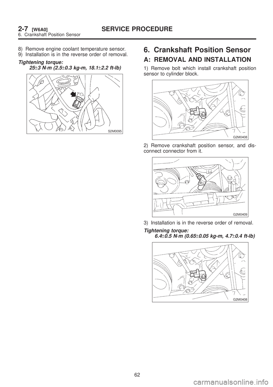
8) Remove engine coolant temperature sensor.
9) Installation is in the reverse order of removal.
Tightening torque:
25
±3 N´m (2.5±0.3 kg-m, 18.1±2.2 ft-lb)
S2M0095
6. Crankshaft Position Sensor
A: REMOVAL AND INSTALLATION
1) Remove bolt which install crankshaft position
sensor to cylinder block.
G2M0408
2) Remove crankshaft position sensor, and dis-
connect connector from it.
G2M0409
3) Installation is in the reverse order of removal.
Tightening torque:
6.4
±0.5 N´m (0.65±0.05 kg-m, 4.7±0.4 ft-lb)
G2M0408
62
2-7[W6A0]SERVICE PROCEDURE
6. Crankshaft Position Sensor
Page 324 of 1456
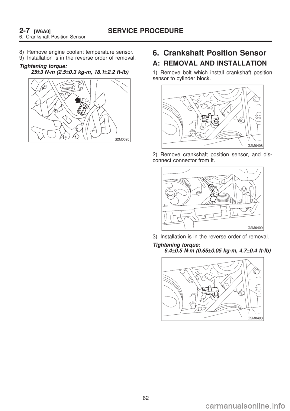
8) Remove engine coolant temperature sensor.
9) Installation is in the reverse order of removal.
Tightening torque:
25
±3 N´m (2.5±0.3 kg-m, 18.1±2.2 ft-lb)
S2M0095
6. Crankshaft Position Sensor
A: REMOVAL AND INSTALLATION
1) Remove bolt which install crankshaft position
sensor to cylinder block.
G2M0408
2) Remove crankshaft position sensor, and dis-
connect connector from it.
G2M0409
3) Installation is in the reverse order of removal.
Tightening torque:
6.4
±0.5 N´m (0.65±0.05 kg-m, 4.7±0.4 ft-lb)
G2M0408
62
2-7[W6A0]SERVICE PROCEDURE
6. Crankshaft Position Sensor