engine coolant SUBARU LEGACY 1999 Service Service Manual
[x] Cancel search | Manufacturer: SUBARU, Model Year: 1999, Model line: LEGACY, Model: SUBARU LEGACY 1999Pages: 1456, PDF Size: 59.93 MB
Page 341 of 1456
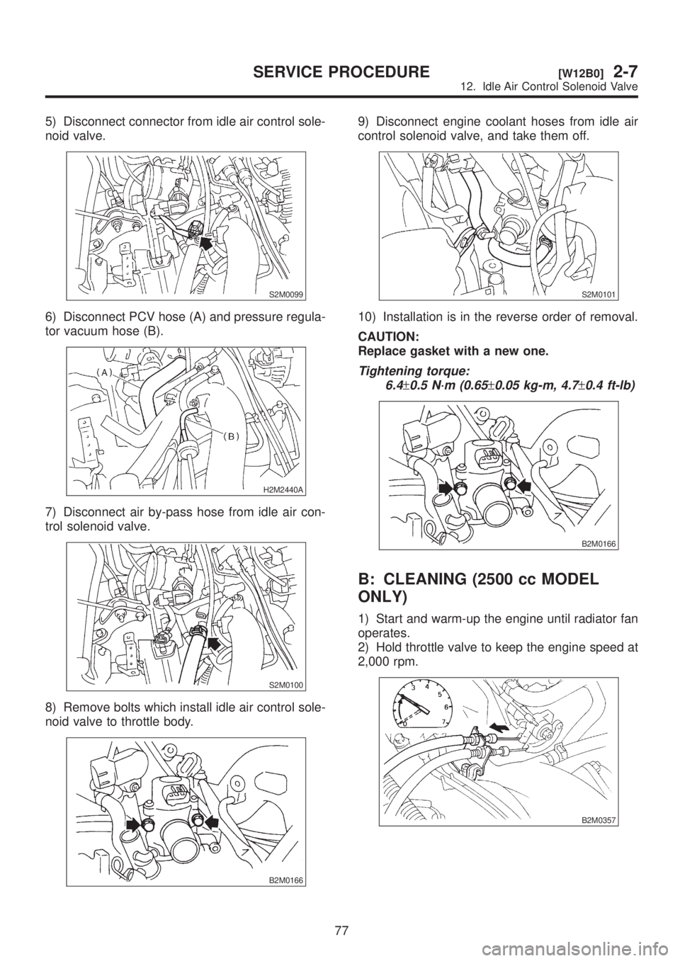
5) Disconnect connector from idle air control sole-
noid valve.
S2M0099
6) Disconnect PCV hose (A) and pressure regula-
tor vacuum hose (B).
H2M2440A
7) Disconnect air by-pass hose from idle air con-
trol solenoid valve.
S2M0100
8) Remove bolts which install idle air control sole-
noid valve to throttle body.
B2M0166
9) Disconnect engine coolant hoses from idle air
control solenoid valve, and take them off.
S2M0101
10) Installation is in the reverse order of removal.
CAUTION:
Replace gasket with a new one.
Tightening torque:
6.4
±0.5 N´m (0.65±0.05 kg-m, 4.7±0.4 ft-lb)
B2M0166
B: CLEANING (2500 cc MODEL
ONLY)
1) Start and warm-up the engine until radiator fan
operates.
2) Hold throttle valve to keep the engine speed at
2,000 rpm.
B2M0357
77
[W12B0]2-7SERVICE PROCEDURE
12. Idle Air Control Solenoid Valve
Page 358 of 1456
![SUBARU LEGACY 1999 Service Service Manual 4) Install air cleaner assembly. (California spec.
vehicles only) <Ref. to 2-7 [W1A1].>
B2M2320
5) Connect battery ground cable to battery ground
terminal.
B2M1723
2. 2500 cc MODEL
1) Install knock se](/img/17/57435/w960_57435-357.png "SUBARU LEGACY 1999 Service Service Manual 4) Install air cleaner assembly. (California spec.
vehicles only) <Ref. to 2-7 [W1A1].>
B2M2320
5) Connect battery ground cable to battery ground
terminal.
B2M1723
2. 2500 cc MODEL
1) Install knock se")
4) Install air cleaner assembly. (California spec.
vehicles only)
B2M2320
5) Connect battery ground cable to battery ground
terminal.
B2M1723
2. 2500 cc MODEL
1) Install knock sensor to cylinder block.
NOTE:
The knock sensor cord which is extracted from the
sensor must be positioned at a 45É angle against
the rear side of the engine.
Tightening torque:
23.5
±2.9 N´m (2.4±0.3 kg-m, 17.3±2.1 ft-lb)
B2M1682A
2) Connect knock sensor connector.
B2M1686
NOTE:
The knock sensor connector must be connected
behind the engine coolant hose within the engine
components.
B2M1688A
B2M1689A
92
2-7[W19B2]SERVICE PROCEDURE
19. Knock Sensor
Page 439 of 1456
1. Engine
A: GENERAL PRECAUTION
(1) Remove or install engine in an area where
chain hoists, lifting devices, etc. are available for
ready use.
(2) Be sure not to damage coated surfaces of
body panels with tools or stain seats and windows
with coolant or oil. Place a cover over fenders, as
required, for protection.
(3) Prior to starting work, prepare the following:
Service tools, clean cloth, containers to catch cool-
ant and oil, wire ropes, chain hoist, transmission
jacks, etc.
(4) Lift-up or lower the vehicle when necessary.
Make sure to support the correct positions.
B: REMOVAL
1) Set the vehicle on lift arms.
2) Open front hood and support with a stay.
3) Release fuel pressure.
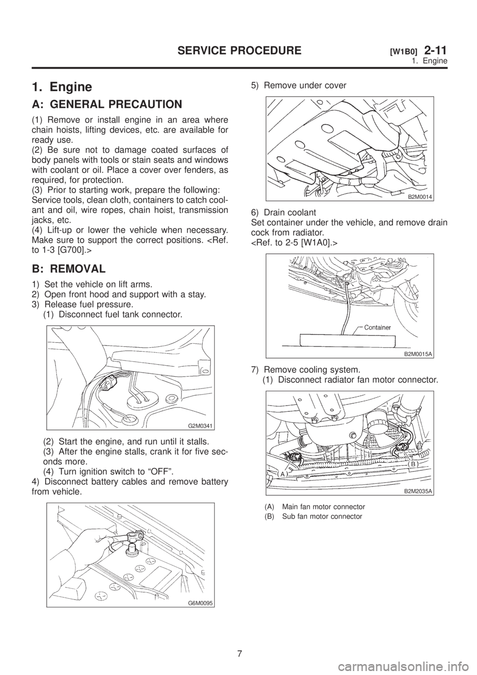
(1) Disconnect fuel tank connector.
G2M0341
(2) Start the engine, and run until it stalls.
(3) After the engine stalls, crank it for five sec-
onds more.
(4) Turn ignition switch to ªOFFº.
4) Disconnect battery cables and remove battery
from vehicle.
G6M0095
5) Remove under cover
B2M0014
6) Drain coolant
Set container under the vehicle, and remove drain
cock from radiator.
B2M0015A
7) Remove cooling system.
(1) Disconnect radiator fan motor connector.
B2M2035A
(A) Main fan motor connector
(B) Sub fan motor connector
7
[W1B0]2-11SERVICE PROCEDURE
1. Engine
Page 452 of 1456
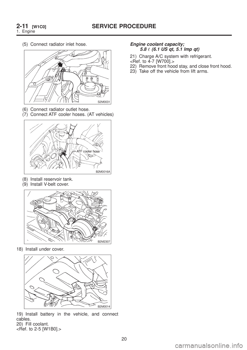
(5) Connect radiator inlet hose.
S2M0031
(6) Connect radiator outlet hose.
(7) Connect ATF cooler hoses. (AT vehicles)
B2M0016A
(8) Install reservoir tank.
(9) Install V-belt cover.
B2M2307
18) Install under cover.
B2M0014
19) Install battery in the vehicle, and connect
cables.
20) Fill coolant.
Engine coolant capacity;
5.8
(6.1 US qt, 5.1 lmp qt)
21) Charge A/C system with refrigerant.
22) Remove front hood stay, and close front hood.
23) Take off the vehicle from lift arms.
20
2-11[W1C0]SERVICE PROCEDURE
1. Engine
Page 568 of 1456
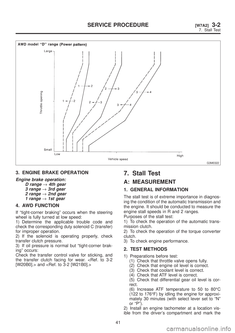
G3M0322
3. ENGINE BRAKE OPERATION
Engine brake operation:
D range
®4th gear
3 range
®3rd gear
2 range
®2nd gear
1 range
®1st gear
4. AWD FUNCTION
If ªtight-corner brakingº occurs when the steering
wheel is fully turned at low speed:
1) Determine the applicable trouble code and
check the corresponding duty solenoid C (transfer)
for improper operation.
2) If the solenoid is operating properly, check
transfer clutch pressure.
3) If oil pressure is normal but ªtight-corner brak-
ingº occurs:
Check the transfer control valve for sticking, and
the transfer clutch facing for wear.
7. Stall Test
A: MEASUREMENT
1. GENERAL INFORMATION
The stall test is of extreme importance in diagnos-
ing the condition of the automatic transmission and
the engine. It should be conducted to measure the
engine stall speeds in R and 2 ranges.
Purposes of the stall test:
1) To check the operation of the automatic trans-
mission clutch.
2) To check the operation of the torque converter
clutch.
3) To check engine performance.
2. TEST METHODS
1) Preparations before test:
(1) Check that throttle valve opens fully.
(2) Check that engine oil level is correct.
(3) Check that coolant level is correct.
(4) Check that ATF level is correct.
(5) Check that differential gear oil level is cor-
rect.
(6) Increase ATF temperature to 50 to 80ÉC
(122 to 176ÉF) by idling the engine for approxi-
mately 30 minutes (with select lever set to ªNº
or ªPº).
2) Install an engine tachometer at a location vis-
ible from the driver's compartment and mark the
41
[W7A2]3-2SERVICE PROCEDURE
7. Stall Test
Page 569 of 1456
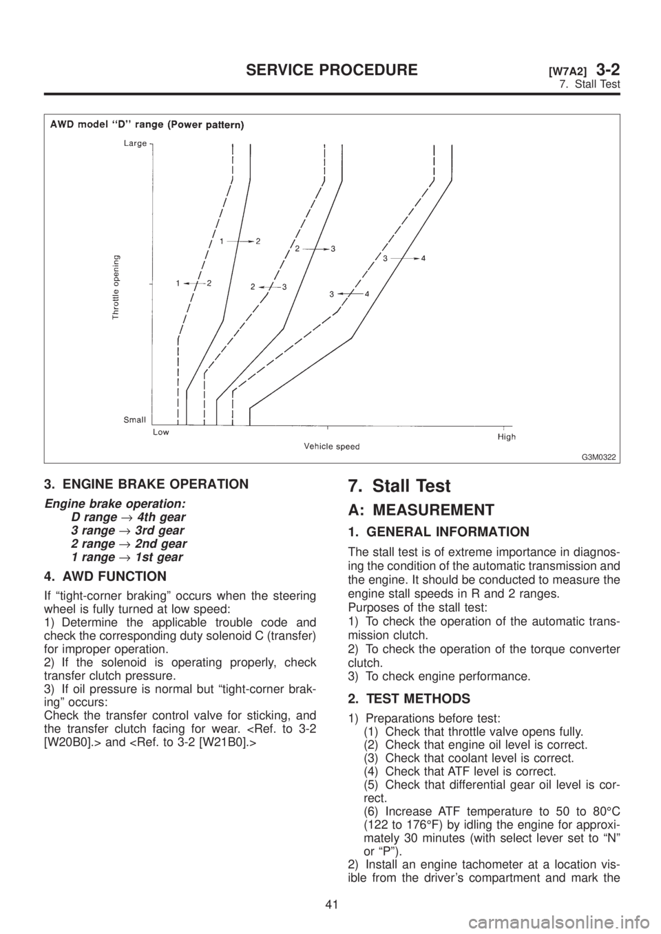
G3M0322
3. ENGINE BRAKE OPERATION
Engine brake operation:
D range
®4th gear
3 range
®3rd gear
2 range
®2nd gear
1 range
®1st gear
4. AWD FUNCTION
If ªtight-corner brakingº occurs when the steering
wheel is fully turned at low speed:
1) Determine the applicable trouble code and
check the corresponding duty solenoid C (transfer)
for improper operation.
2) If the solenoid is operating properly, check
transfer clutch pressure.
3) If oil pressure is normal but ªtight-corner brak-
ingº occurs:
Check the transfer control valve for sticking, and
the transfer clutch facing for wear.
7. Stall Test
A: MEASUREMENT
1. GENERAL INFORMATION
The stall test is of extreme importance in diagnos-
ing the condition of the automatic transmission and
the engine. It should be conducted to measure the
engine stall speeds in R and 2 ranges.
Purposes of the stall test:
1) To check the operation of the automatic trans-
mission clutch.
2) To check the operation of the torque converter
clutch.
3) To check engine performance.
2. TEST METHODS
1) Preparations before test:
(1) Check that throttle valve opens fully.
(2) Check that engine oil level is correct.
(3) Check that coolant level is correct.
(4) Check that ATF level is correct.
(5) Check that differential gear oil level is cor-
rect.
(6) Increase ATF temperature to 50 to 80ÉC
(122 to 176ÉF) by idling the engine for approxi-
mately 30 minutes (with select lever set to ªNº
or ªPº).
2) Install an engine tachometer at a location vis-
ible from the driver's compartment and mark the
41
[W7A2]3-2SERVICE PROCEDURE
7. Stall Test
Page 967 of 1456
1. Precaution
A: SUPPLEMENTAL RESTRAINT
SYSTEM ªAIRBAGº
CAUTION:
IAll Airbag system wiring harness and con-
nectors are colored yellow. Do not use electri-
cal test equipment on these circuit.
IBe careful not to damage Airbag system wir-
ing harness when servicing the instrument
panel, heater unit, blower motor and control
unit.
Airbag system wiring harness is routed near the
instrument panel, heater unit, blower motor and
control unit.
2. Heater Unit
A: REMOVAL AND INSTALLATION
1) Disconnect GND cable from battery.
2) Remove heater hoses (inlet, outlet) in engine
compartment.
NOTE:
Drain as much coolant from heater unit as
possible, and plug disconnected hose with cloth.
3) Remove instrument panel.
4) Remove steering support beam.
5) Remove evaporator. (With A/C model)
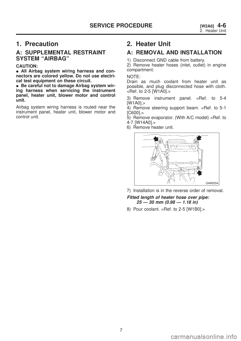
6) Remove heater unit.
G4M0554
7) Installation is in the reverse order of removal.
Fitted length of heater hose over pipe:
25 Ð 30 mm (0.98 Ð 1.18 in)
8) Pour coolant.
7
[W2A0]4-6SERVICE PROCEDURE
2. Heater Unit
Page 968 of 1456
1. Precaution
A: SUPPLEMENTAL RESTRAINT
SYSTEM ªAIRBAGº
CAUTION:
IAll Airbag system wiring harness and con-
nectors are colored yellow. Do not use electri-
cal test equipment on these circuit.
IBe careful not to damage Airbag system wir-
ing harness when servicing the instrument
panel, heater unit, blower motor and control
unit.
Airbag system wiring harness is routed near the
instrument panel, heater unit, blower motor and
control unit.
2. Heater Unit
A: REMOVAL AND INSTALLATION
1) Disconnect GND cable from battery.
2) Remove heater hoses (inlet, outlet) in engine
compartment.
NOTE:
Drain as much coolant from heater unit as
possible, and plug disconnected hose with cloth.
3) Remove instrument panel.
4) Remove steering support beam.
5) Remove evaporator. (With A/C model)
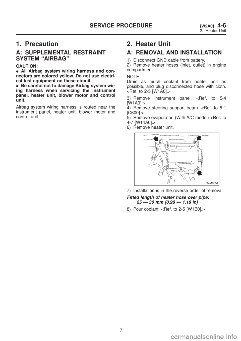
6) Remove heater unit.
G4M0554
7) Installation is in the reverse order of removal.
Fitted length of heater hose over pipe:
25 Ð 30 mm (0.98 Ð 1.18 in)
8) Pour coolant.
7
[W2A0]4-6SERVICE PROCEDURE
2. Heater Unit
Page 1413 of 1456
![SUBARU LEGACY 1999 Service Service Manual 7. Electrical Unit Location
A: LIST
Electrical unit Index No.
ABS control module <Ref. to 4-4 [T300].>
ABS G sensor (MT) <Ref. to 4-4 [T300].>
A/C compressor relay <Ref. to 6-3 [D7B1].>
A/C fuse <Ref.](/img/17/57435/w960_57435-1412.png "SUBARU LEGACY 1999 Service Service Manual 7. Electrical Unit Location
A: LIST
Electrical unit Index No.
ABS control module <Ref. to 4-4 [T300].>
ABS G sensor (MT) <Ref. to 4-4 [T300].>
A/C compressor relay <Ref. to 6-3 [D7B1].>
A/C fuse <Ref.")
7. Electrical Unit Location
A: LIST
Electrical unit Index No.
ABS control module
ABS G sensor (MT)
A/C compressor relay
A/C fuse
A/C main fan relay 1
A/C main fan relay 2
A/C pressure switch
A/C sub fan relay 2
ATF temperature sensor
Blower motor resistor
Blower relay
Camshaft position sensor
Check connector
Clutch switch (MT)
Crankshaft position sensor
Cruise control module
Cruise control pump
Data link connector (for
OBD-II G.S.T.)
Data link connector (for
S.S.M.)
Diagnosis connector
Diagnosis terminal (Ground)
Door lock timer
Engine control module
Engine coolant temperature
sensor
Engine hood switch (Secu-
rity)
Evaporator thermoswitch
F/B
FRESH/RECIRC actuator
Fuel pump relay
Fuel gauge module
Fuel gauge sub module
(AWD)
FWD switch (AT)
Headlight alarm relay
(Security)
Headlight relay LH
Electrical unit Index No.
Headlight relay RH
Horn relay
Hydraulic unit (ABS)
Ignition coil
Ignitor
Idle air control solenoid
valve
Illumination control module
Inhibitor switch
Knock sensor
Main fan relay
Main relay
Mass air flow sensor
Mode actuator
M/B
Oil pressure switch
Oxygen sensor
Pedal stroke sensor (TCS)
Power window and sunroof
relay
Power window circuit
breaker
Purge control solenoid valve
Rear defogger relay
Seat belt timer
Security control module
Shift lock control module
Starter interrupt relay (Secu-
rity)
Stop & brake switch (With
cruise control)
Sunroof control module
Tail and illumination relay
TCS control module
TCS motor relay
TCS valve relay
Throttle position sensor
Test mode connector
Transmission control mod-
ule
Turn & hazard module
Vehicle speed sensor 1
Vehicle speed sensor 2
133
[D7A0]6-3WIRING DIAGRAM
7. Electrical Unit Location
Page 1434 of 1456
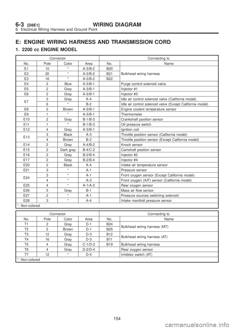
E: ENGINE WIRING HARNESS AND TRANSMISSION CORD
1. 2200 cc ENGINE MODEL
Connector Connecting to
No. Pole Color Area No. Name
E1 10 * A-3/B-2 B20
Bulkhead wiring harness E2 20 * A-3/B-2 B21
E3 16 * A-3/B-2 B22
E4 2 Blue A-3/B-1 Purge control solenoid valve
E5 2 Gray A-3/B-1 Injector #1
E6 2 Gray A-3/B-1 Injector #3
E73 Gray A-4 Idle air control solenoid valve (California model)
6 * B-2 Idle air control solenoid valve (Except California model)
E8 2 Brown A-3/B-1 Engine coolant temperature sensor
E9 1 * A-3/B-1 Thermometer
E10 2 Gray B-1/B-3 Crankshaft position sensor
E11 1 * B-1/B-3 Oil pressure switch
E12 4 Gray A-3/B-1 Ignition coil
E133 Black A-3 Throttle position sensor (California model)
4 Brown B-2 Throttle position sensor (Except California model)
E14 2 Gray A-4/B-2 Knock sensor
E15 2 Dark gray B-4/C-2 Camshaft position sensor
E16 2 Gray B-2/B-4 Injector #2
E17 2 Gray B-2/B-4 Injector #4
E20 2 Black A-4 Intake air temperature sensor
E21 3 * A-1 Pressure sensor
E243 * A-1 Front oxygen sensor (Except California model)
4 * A-3 Front oxygen (A/F) sensor (California model)
E25 4 * A-1/A-3 Rear oxygen sensor
E26 5 Gray B-1 Mass air flow sensor
E27 2 * A-1 Pressure sources switching solenoid
E28 3 * A-4 Intake manifold pressure sensor
*: Non-colored
Connector Connecting to
No. Pole Color Area No. Name
T1 2 Gray D-1 B24
Bulkhead wiring harness (MT)
T2 2 Brown D-1 B25
T3 12 Gray D-3 B12
Bulkhead wiring harness (AT)
T4 16 Gray D-3 B11
T5 4 Gray C-1/D-3 B19 Bulkhead wiring harness
T6 4 Gray D-2/D-4 Rear oxygen sensor
T7 12 * D-4 Inhibitor switch (AT)
*: Non-colored
154
6-3[D8E1]WIRING DIAGRAM
8. Electrical Wiring Harness and Ground Point