SUBARU LEGACY 1999 Service Repair Manual
Manufacturer: SUBARU, Model Year: 1999, Model line: LEGACY, Model: SUBARU LEGACY 1999Pages: 1456, PDF Size: 59.93 MB
Page 611 of 1456
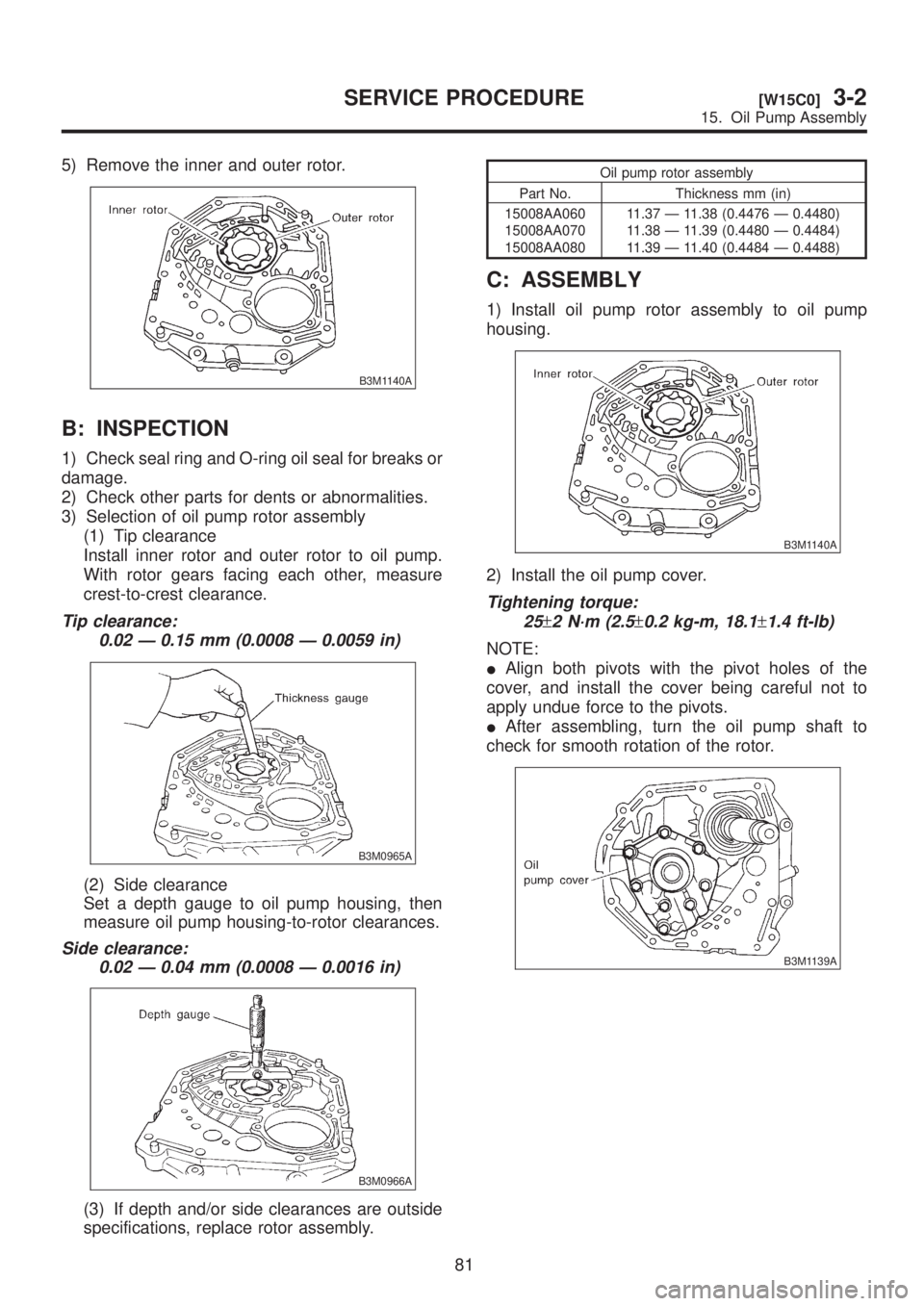
5) Remove the inner and outer rotor.
B3M1140A
B: INSPECTION
1) Check seal ring and O-ring oil seal for breaks or
damage.
2) Check other parts for dents or abnormalities.
3) Selection of oil pump rotor assembly
(1) Tip clearance
Install inner rotor and outer rotor to oil pump.
With rotor gears facing each other, measure
crest-to-crest clearance.
Tip clearance:
0.02 Ð 0.15 mm (0.0008 Ð 0.0059 in)
B3M0965A
(2) Side clearance
Set a depth gauge to oil pump housing, then
measure oil pump housing-to-rotor clearances.
Side clearance:
0.02 Ð 0.04 mm (0.0008 Ð 0.0016 in)
B3M0966A
(3) If depth and/or side clearances are outside
specifications, replace rotor assembly.
Oil pump rotor assembly
Part No. Thickness mm (in)
15008AA060
15008AA070
15008AA08011.37 Ð 11.38 (0.4476 Ð 0.4480)
11.38 Ð 11.39 (0.4480 Ð 0.4484)
11.39 Ð 11.40 (0.4484 Ð 0.4488)
C: ASSEMBLY
1) Install oil pump rotor assembly to oil pump
housing.
B3M1140A
2) Install the oil pump cover.
Tightening torque:
25
±2 N´m (2.5±0.2 kg-m, 18.1±1.4 ft-lb)
NOTE:
IAlign both pivots with the pivot holes of the
cover, and install the cover being careful not to
apply undue force to the pivots.
IAfter assembling, turn the oil pump shaft to
check for smooth rotation of the rotor.
B3M1139A
81
[W15C0]3-2SERVICE PROCEDURE
15. Oil Pump Assembly
Page 612 of 1456
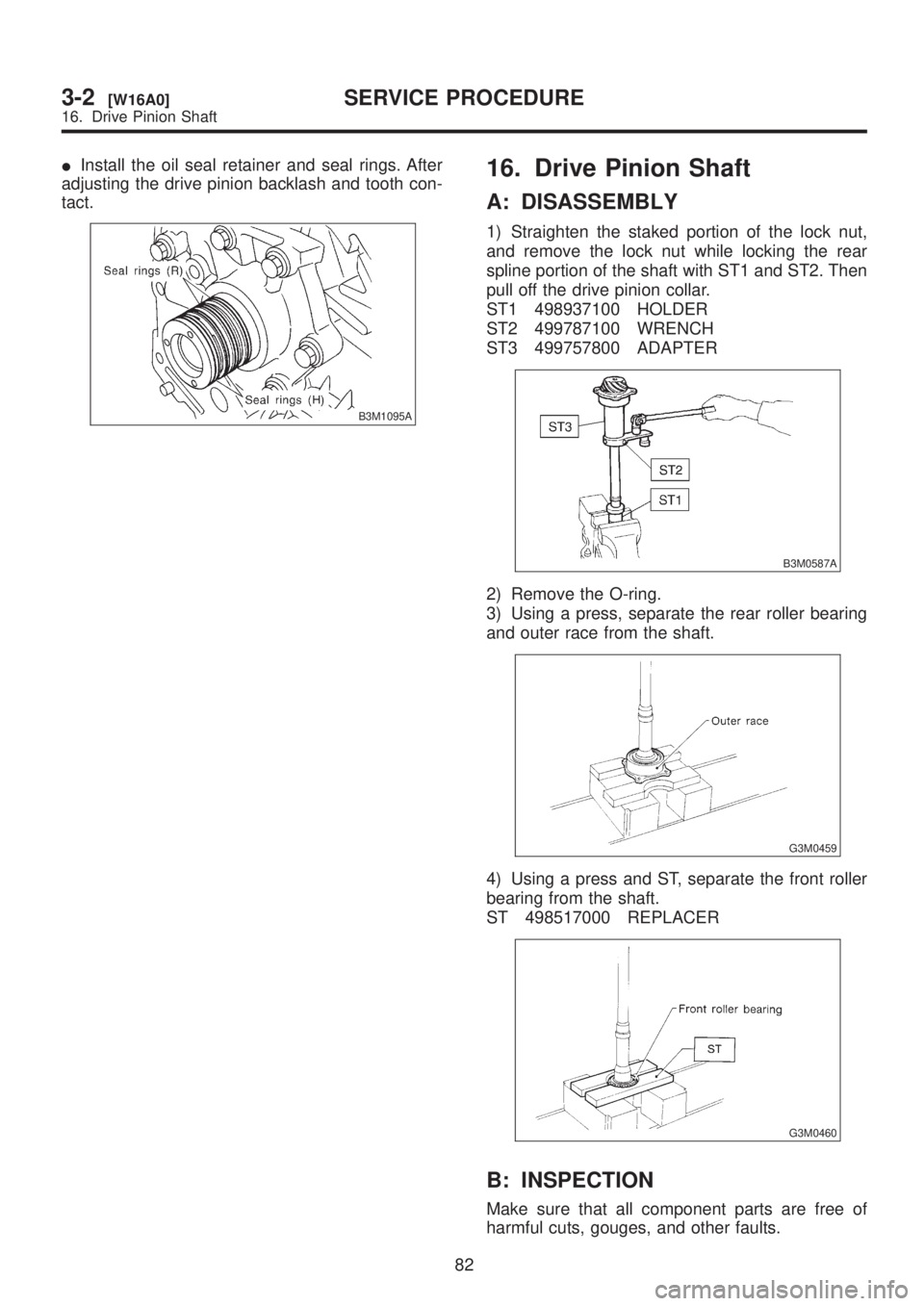
IInstall the oil seal retainer and seal rings. After
adjusting the drive pinion backlash and tooth con-
tact.
B3M1095A
16. Drive Pinion Shaft
A: DISASSEMBLY
1) Straighten the staked portion of the lock nut,
and remove the lock nut while locking the rear
spline portion of the shaft with ST1 and ST2. Then
pull off the drive pinion collar.
ST1 498937100 HOLDER
ST2 499787100 WRENCH
ST3 499757800 ADAPTER
B3M0587A
2) Remove the O-ring.
3) Using a press, separate the rear roller bearing
and outer race from the shaft.
G3M0459
4) Using a press and ST, separate the front roller
bearing from the shaft.
ST 498517000 REPLACER
G3M0460
B: INSPECTION
Make sure that all component parts are free of
harmful cuts, gouges, and other faults.
82
3-2[W16A0]SERVICE PROCEDURE
16. Drive Pinion Shaft
Page 613 of 1456
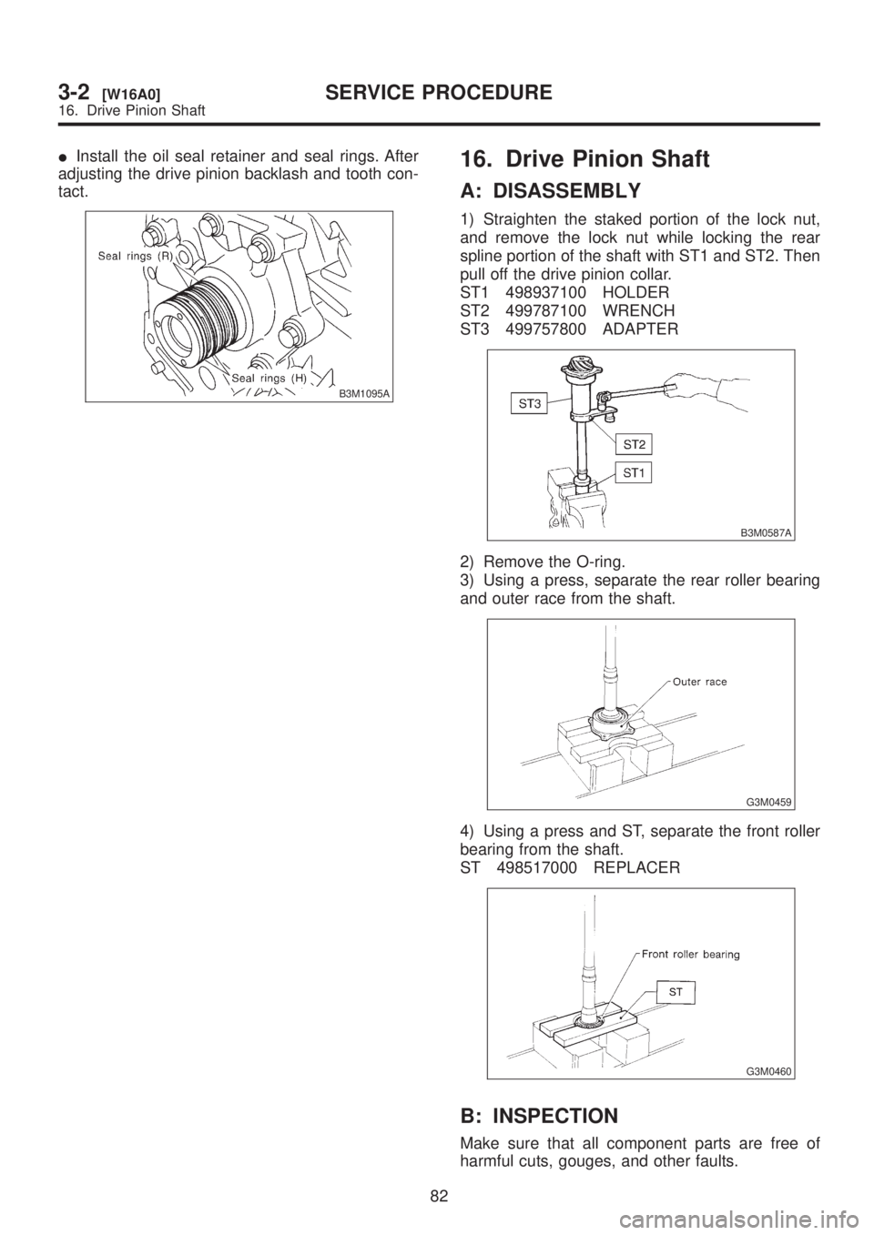
IInstall the oil seal retainer and seal rings. After
adjusting the drive pinion backlash and tooth con-
tact.
B3M1095A
16. Drive Pinion Shaft
A: DISASSEMBLY
1) Straighten the staked portion of the lock nut,
and remove the lock nut while locking the rear
spline portion of the shaft with ST1 and ST2. Then
pull off the drive pinion collar.
ST1 498937100 HOLDER
ST2 499787100 WRENCH
ST3 499757800 ADAPTER
B3M0587A
2) Remove the O-ring.
3) Using a press, separate the rear roller bearing
and outer race from the shaft.
G3M0459
4) Using a press and ST, separate the front roller
bearing from the shaft.
ST 498517000 REPLACER
G3M0460
B: INSPECTION
Make sure that all component parts are free of
harmful cuts, gouges, and other faults.
82
3-2[W16A0]SERVICE PROCEDURE
16. Drive Pinion Shaft
Page 614 of 1456
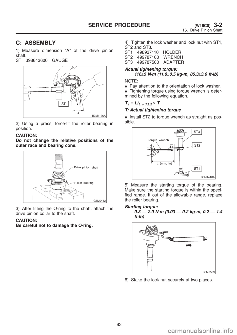
C: ASSEMBLY
1) Measure dimension ªAº of the drive pinion
shaft.
ST 398643600 GAUGE
B3M1176A
2) Using a press, force-fit the roller bearing in
position.
CAUTION:
Do not change the relative positions of the
outer race and bearing cone.
G3M0462
3) After fitting the O-ring to the shaft, attach the
drive pinion collar to the shaft.
CAUTION:
Be careful not to damage the O-ring.4) Tighten the lock washer and lock nut with ST1,
ST2 and ST3.
ST1 498937110 HOLDER
ST2 499787100 WRENCH
ST3 499787500 ADAPTER
Actual tightening torque:
11 6
±5 N´m (11.8±0.5 kg-m, 85.3±3.6 ft-lb)
NOTE:
IPay attention to the orientation of lock washer.
ITightening torque using torque wrench is deter-
mined by the following equation.
T1=L/L + 72.2´T
T: Actual tightening torque
IInstall ST2 to torque wrench as straight as pos-
sible.
B3M1410A
5) Measure the starting torque of the bearing.
Make sure the starting torque is within the speci-
fied range. If out of the allowable range, replace
the roller bearing.
Starting torque:
0.3 Ð 2.0 N´m (0.03 Ð 0.2 kg-m, 0.2 Ð 1.4
ft-lb)
B3M0589
6) Stake the lock nut securely at two places.
83
[W16C0]3-2SERVICE PROCEDURE
16. Drive Pinion Shaft
Page 615 of 1456
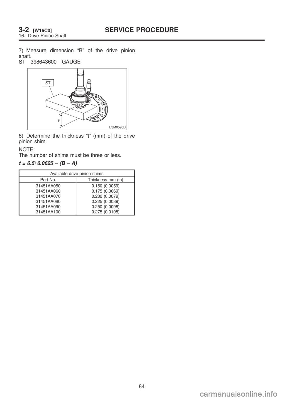
7) Measure dimension ªBº of the drive pinion
shaft.
ST 398643600 GAUGE
B3M0590D
8) Determine the thickness ªtº (mm) of the drive
pinion shim.
NOTE:
The number of shims must be three or less.
t = 6.5±0.0625 þ (B þ A)
Available drive pinion shims
Part No. Thickness mm (in)
31451AA050
31451AA060
31451AA070
31451AA080
31451AA090
31451AA1000.150 (0.0059)
0.175 (0.0069)
0.200 (0.0079)
0.225 (0.0089)
0.250 (0.0098)
0.275 (0.0108)
84
3-2[W16C0]SERVICE PROCEDURE
16. Drive Pinion Shaft
Page 616 of 1456
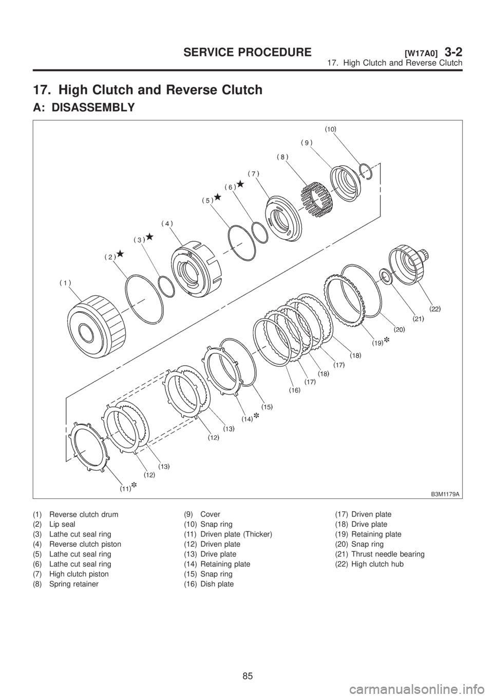
17. High Clutch and Reverse Clutch
A: DISASSEMBLY
B3M1179A
(1) Reverse clutch drum
(2) Lip seal
(3) Lathe cut seal ring
(4) Reverse clutch piston
(5) Lathe cut seal ring
(6) Lathe cut seal ring
(7) High clutch piston
(8) Spring retainer(9) Cover
(10) Snap ring
(11) Driven plate (Thicker)
(12) Driven plate
(13) Drive plate
(14) Retaining plate
(15) Snap ring
(16) Dish plate(17) Driven plate
(18) Drive plate
(19) Retaining plate
(20) Snap ring
(21) Thrust needle bearing
(22) High clutch hub
85
[W17A0]3-2SERVICE PROCEDURE
17. High Clutch and Reverse Clutch
Page 617 of 1456
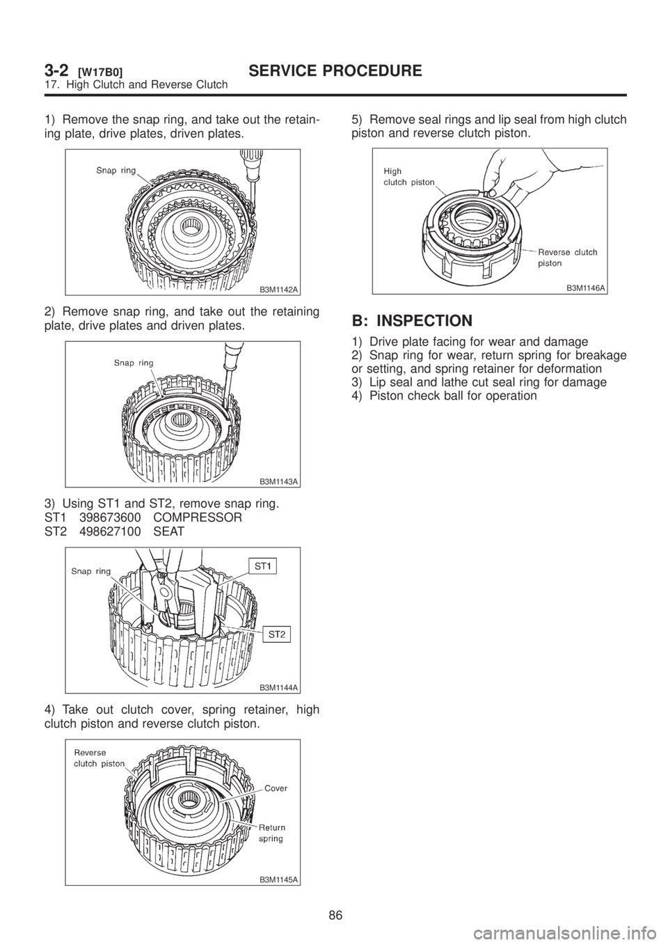
1) Remove the snap ring, and take out the retain-
ing plate, drive plates, driven plates.
B3M1142A
2) Remove snap ring, and take out the retaining
plate, drive plates and driven plates.
B3M1143A
3) Using ST1 and ST2, remove snap ring.
ST1 398673600 COMPRESSOR
ST2 498627100 SEAT
B3M1144A
4) Take out clutch cover, spring retainer, high
clutch piston and reverse clutch piston.
B3M1145A
5) Remove seal rings and lip seal from high clutch
piston and reverse clutch piston.
B3M1146A
B: INSPECTION
1) Drive plate facing for wear and damage
2) Snap ring for wear, return spring for breakage
or setting, and spring retainer for deformation
3) Lip seal and lathe cut seal ring for damage
4) Piston check ball for operation
86
3-2[W17B0]SERVICE PROCEDURE
17. High Clutch and Reverse Clutch
Page 618 of 1456
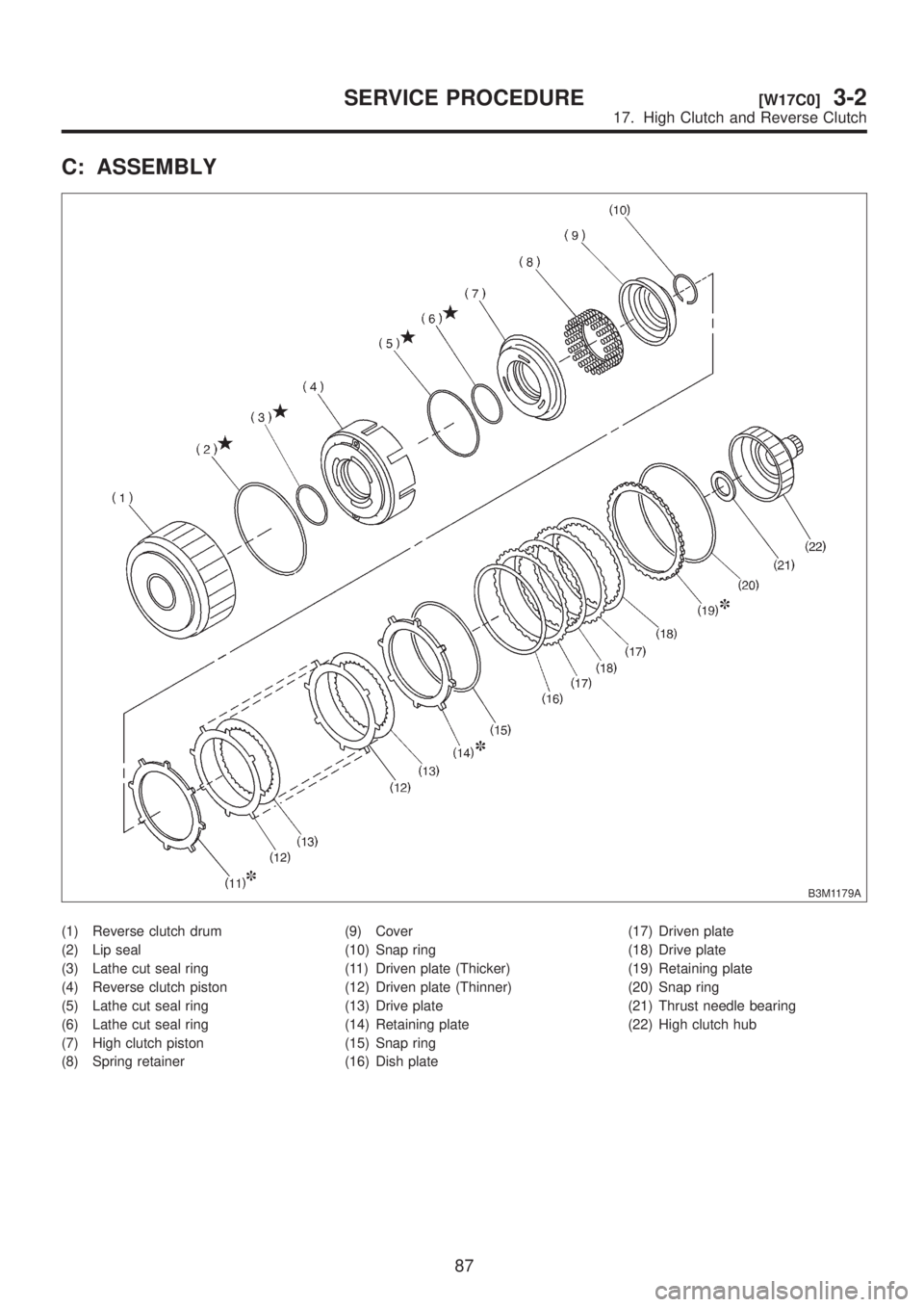
C: ASSEMBLY
B3M1179A
(1) Reverse clutch drum
(2) Lip seal
(3) Lathe cut seal ring
(4) Reverse clutch piston
(5) Lathe cut seal ring
(6) Lathe cut seal ring
(7) High clutch piston
(8) Spring retainer(9) Cover
(10) Snap ring
(11) Driven plate (Thicker)
(12) Driven plate (Thinner)
(13) Drive plate
(14) Retaining plate
(15) Snap ring
(16) Dish plate(17) Driven plate
(18) Drive plate
(19) Retaining plate
(20) Snap ring
(21) Thrust needle bearing
(22) High clutch hub
87
[W17C0]3-2SERVICE PROCEDURE
17. High Clutch and Reverse Clutch
Page 619 of 1456
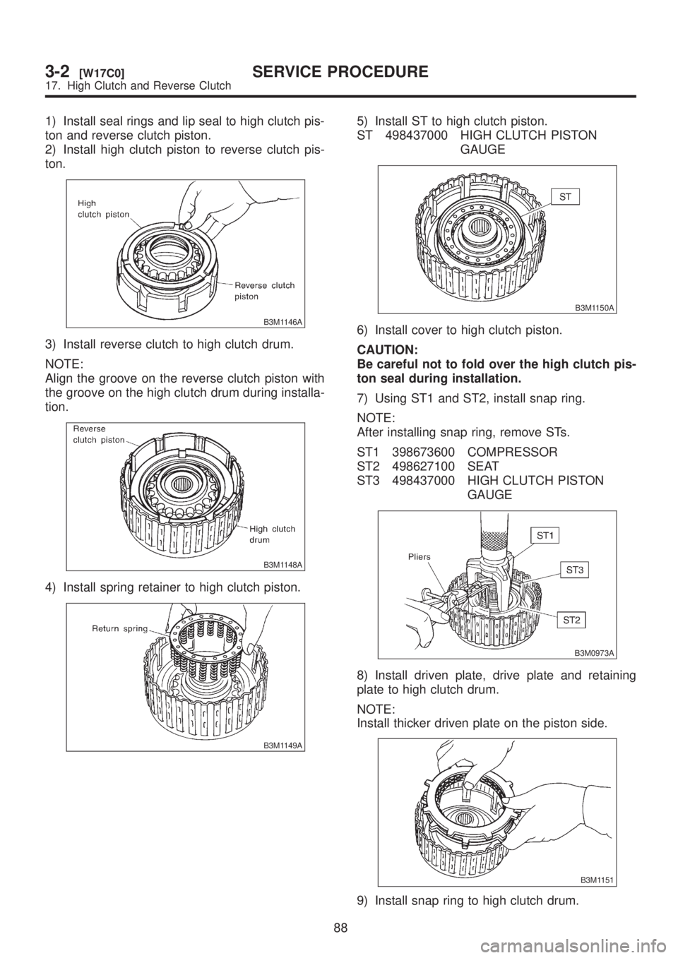
1) Install seal rings and lip seal to high clutch pis-
ton and reverse clutch piston.
2) Install high clutch piston to reverse clutch pis-
ton.
B3M1146A
3) Install reverse clutch to high clutch drum.
NOTE:
Align the groove on the reverse clutch piston with
the groove on the high clutch drum during installa-
tion.
B3M1148A
4) Install spring retainer to high clutch piston.
B3M1149A
5) Install ST to high clutch piston.
ST 498437000 HIGH CLUTCH PISTON
GAUGE
B3M1150A
6) Install cover to high clutch piston.
CAUTION:
Be careful not to fold over the high clutch pis-
ton seal during installation.
7) Using ST1 and ST2, install snap ring.
NOTE:
After installing snap ring, remove STs.
ST1 398673600 COMPRESSOR
ST2 498627100 SEAT
ST3 498437000 HIGH CLUTCH PISTON
GAUGE
B3M0973A
8) Install driven plate, drive plate and retaining
plate to high clutch drum.
NOTE:
Install thicker driven plate on the piston side.
B3M1151
9) Install snap ring to high clutch drum.
88
3-2[W17C0]SERVICE PROCEDURE
17. High Clutch and Reverse Clutch
Page 620 of 1456
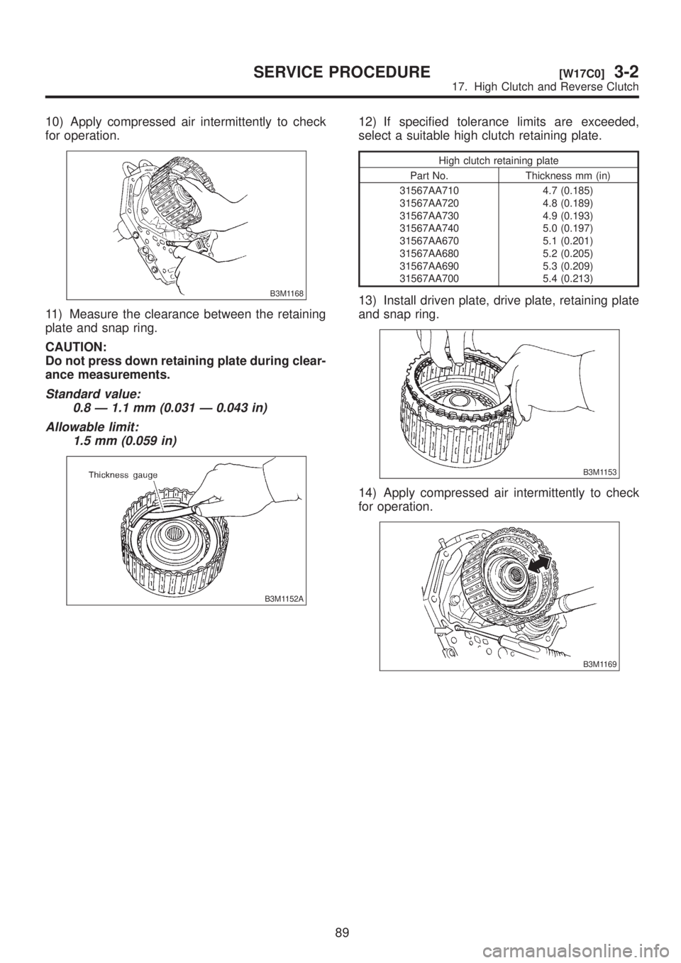
10) Apply compressed air intermittently to check
for operation.
B3M1168
11) Measure the clearance between the retaining
plate and snap ring.
CAUTION:
Do not press down retaining plate during clear-
ance measurements.
Standard value:
0.8 Ð 1.1 mm (0.031 Ð 0.043 in)
Allowable limit:
1.5 mm (0.059 in)
B3M1152A
12) If specified tolerance limits are exceeded,
select a suitable high clutch retaining plate.
High clutch retaining plate
Part No. Thickness mm (in)
31567AA710
31567AA720
31567AA730
31567AA740
31567AA670
31567AA680
31567AA690
31567AA7004.7 (0.185)
4.8 (0.189)
4.9 (0.193)
5.0 (0.197)
5.1 (0.201)
5.2 (0.205)
5.3 (0.209)
5.4 (0.213)
13) Install driven plate, drive plate, retaining plate
and snap ring.
B3M1153
14) Apply compressed air intermittently to check
for operation.
B3M1169
89
[W17C0]3-2SERVICE PROCEDURE
17. High Clutch and Reverse Clutch