SUBARU LEGACY 1999 Service Repair Manual
Manufacturer: SUBARU, Model Year: 1999, Model line: LEGACY, Model: SUBARU LEGACY 1999Pages: 1456, PDF Size: 59.93 MB
Page 601 of 1456
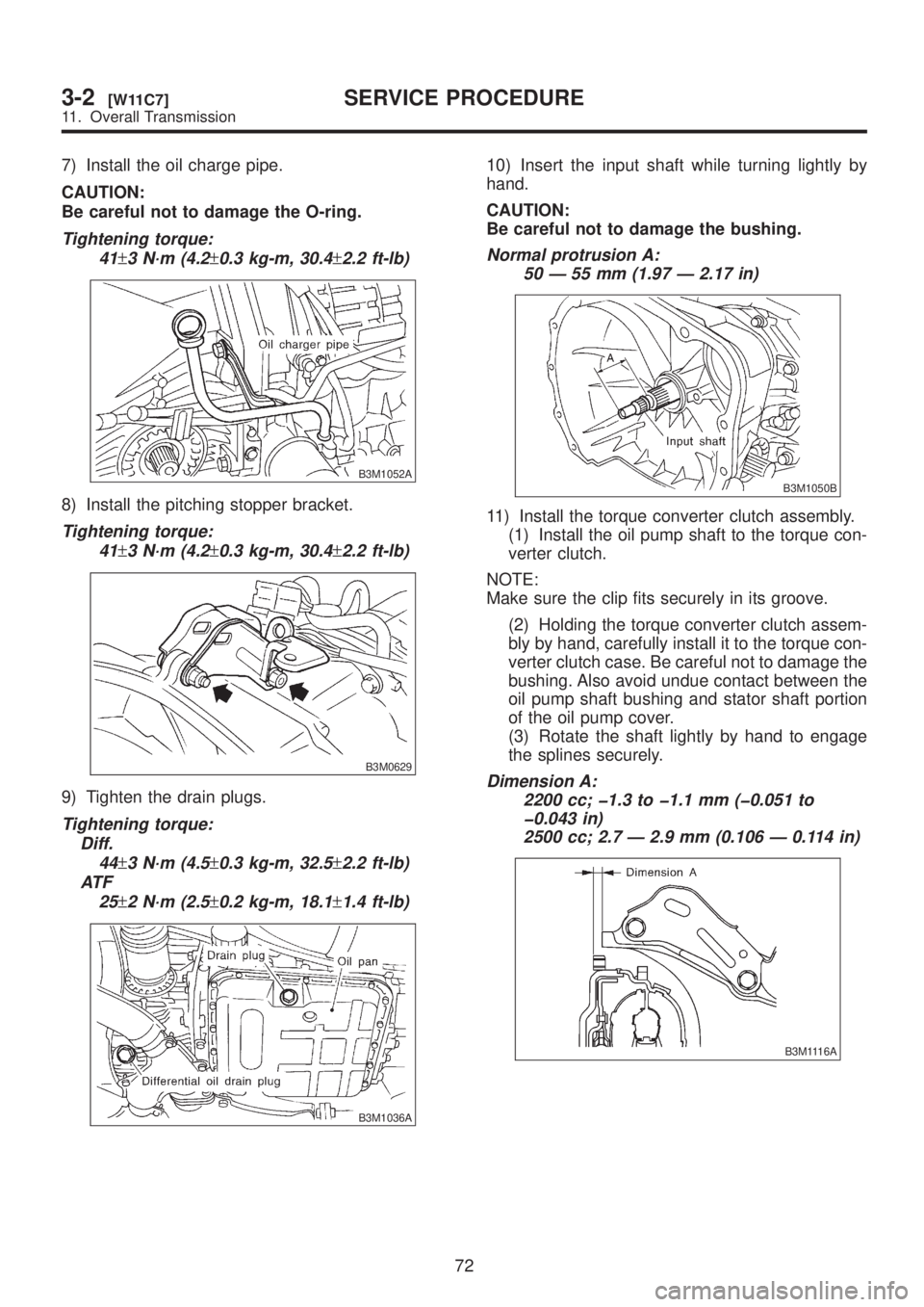
7) Install the oil charge pipe.
CAUTION:
Be careful not to damage the O-ring.
Tightening torque:
41
±3 N´m (4.2±0.3 kg-m, 30.4±2.2 ft-lb)
B3M1052A
8) Install the pitching stopper bracket.
Tightening torque:
41
±3 N´m (4.2±0.3 kg-m, 30.4±2.2 ft-lb)
B3M0629
9) Tighten the drain plugs.
Tightening torque:
Diff.
44
±3 N´m (4.5±0.3 kg-m, 32.5±2.2 ft-lb)
AT F
25
±2 N´m (2.5±0.2 kg-m, 18.1±1.4 ft-lb)
B3M1036A
10) Insert the input shaft while turning lightly by
hand.
CAUTION:
Be careful not to damage the bushing.
Normal protrusion A:
50 Ð 55 mm (1.97 Ð 2.17 in)
B3M1050B
11) Install the torque converter clutch assembly.
(1) Install the oil pump shaft to the torque con-
verter clutch.
NOTE:
Make sure the clip fits securely in its groove.
(2) Holding the torque converter clutch assem-
bly by hand, carefully install it to the torque con-
verter clutch case. Be careful not to damage the
bushing. Also avoid undue contact between the
oil pump shaft bushing and stator shaft portion
of the oil pump cover.
(3) Rotate the shaft lightly by hand to engage
the splines securely.
Dimension A:
2200 cc; þ1.3 to þ1.1 mm (þ0.051 to
þ0.043 in)
2500 cc; 2.7 Ð 2.9 mm (0.106 Ð 0.114 in)
B3M1116A
72
3-2[W11C7]SERVICE PROCEDURE
11. Overall Transmission
Page 602 of 1456
12) Fill ATF and differential gear oil.
NOTE:
After filling oil, insert the oil level gauge into the oil
inlet.
Differential gear oil capacity:
1.1 Ð 1.3
(1.2 Ð 1.4 US qt, 1.0 Ð 1.1
Imp qt)
Automatic transmission fluid capacity:
2200 cc; 8.4 Ð 8.7
(8.9 Ð 9.2 US qt, 7.4
Ð 7.7 Imp qt)
2500 cc; 9.3 Ð 9.6
(9.8 Ð 10.1 US qt,
8.2 Ð 8.4 Imp qt)
Recommended fluid:
Dexron II or Dexron III type automatic
transmission
73
[W11C7]3-2SERVICE PROCEDURE
11. Overall Transmission
Page 603 of 1456
12. Reduction Drive Gear
Assembly
A: DISASSEMBLY
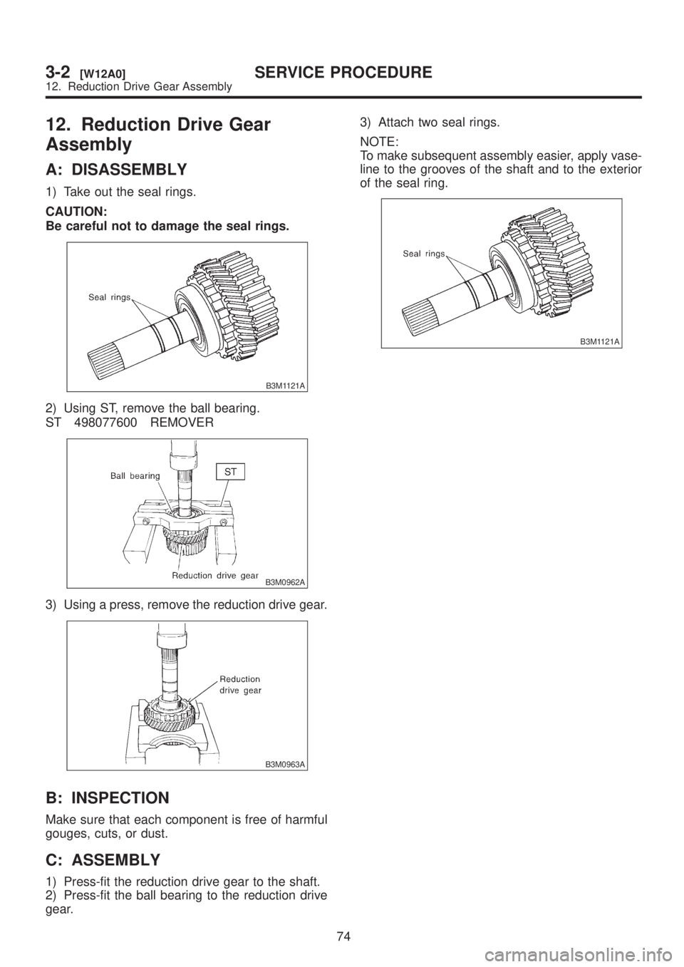
1) Take out the seal rings.
CAUTION:
Be careful not to damage the seal rings.
B3M1121A
2) Using ST, remove the ball bearing.
ST 498077600 REMOVER
B3M0962A
3) Using a press, remove the reduction drive gear.
B3M0963A
B: INSPECTION
Make sure that each component is free of harmful
gouges, cuts, or dust.
C: ASSEMBLY
1) Press-fit the reduction drive gear to the shaft.
2) Press-fit the ball bearing to the reduction drive
gear.3) Attach two seal rings.
NOTE:
To make subsequent assembly easier, apply vase-
line to the grooves of the shaft and to the exterior
of the seal ring.
B3M1121A
74
3-2[W12A0]SERVICE PROCEDURE
12. Reduction Drive Gear Assembly
Page 604 of 1456
13. Reduction Driven Gear
A: REMOVAL
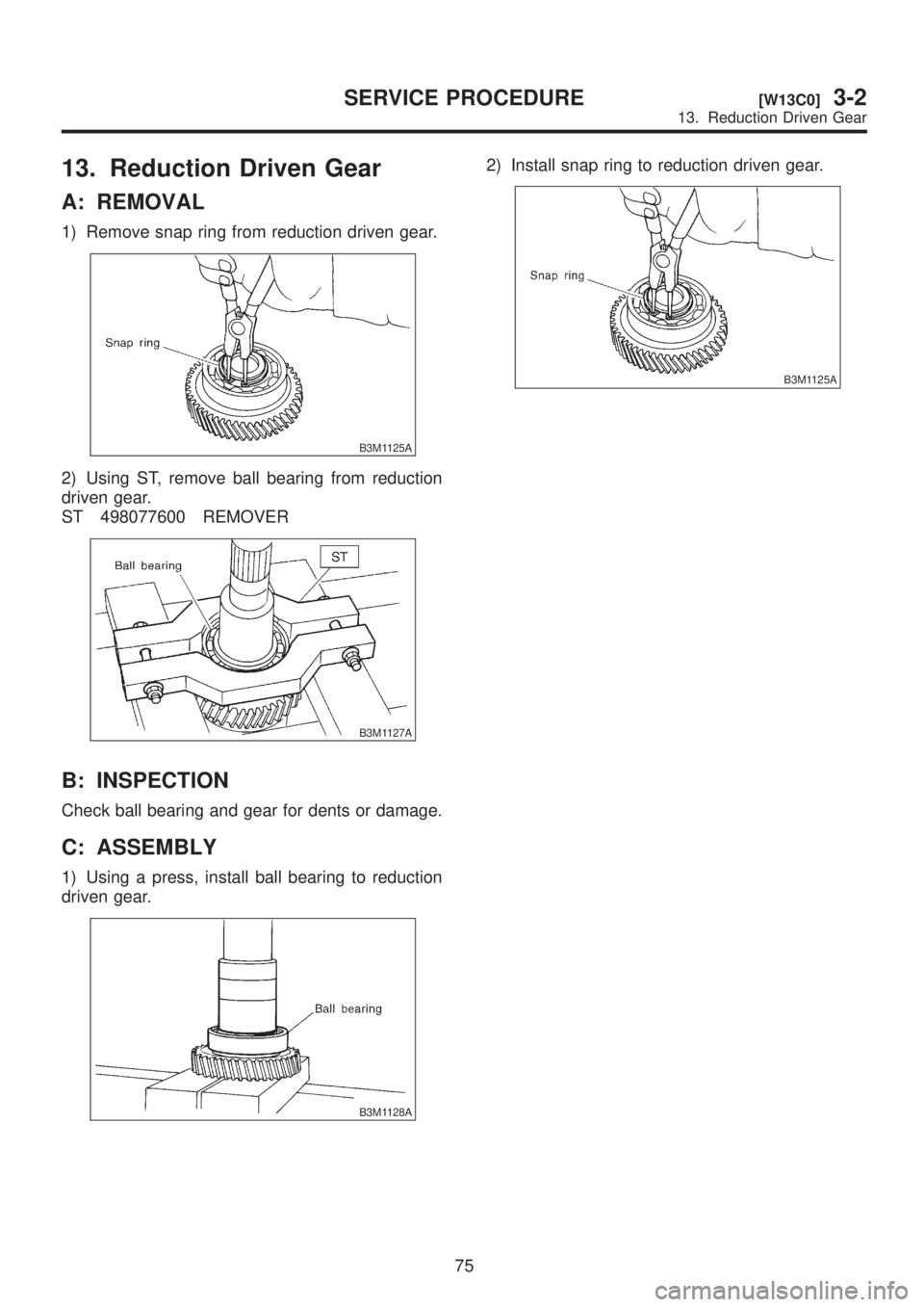
1) Remove snap ring from reduction driven gear.
B3M1125A
2) Using ST, remove ball bearing from reduction
driven gear.
ST 498077600 REMOVER
B3M1127A
B: INSPECTION
Check ball bearing and gear for dents or damage.
C: ASSEMBLY
1) Using a press, install ball bearing to reduction
driven gear.
B3M1128A
2) Install snap ring to reduction driven gear.
B3M1125A
75
[W13C0]3-2SERVICE PROCEDURE
13. Reduction Driven Gear
Page 605 of 1456
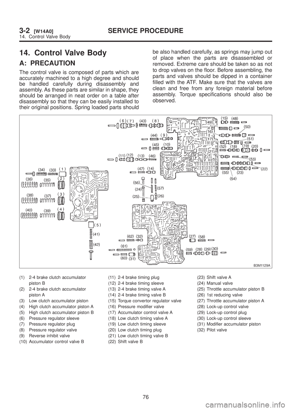
14. Control Valve Body
A: PRECAUTION
The control valve is composed of parts which are
accurately machined to a high degree and should
be handled carefully during disassembly and
assembly. As these parts are similar in shape, they
should be arranged in neat order on a table after
disassembly so that they can be easily installed to
their original positions. Spring loaded parts shouldbe also handled carefully, as springs may jump out
of place when the parts are disassembled or
removed. Extreme care should be taken so as not
to drop valves on the floor. Before assembling, the
parts and valves should be dipped in a container
filled with the ATF. Make sure that the valves are
clean and free from any foreign material before
assembly. Torque specifications should also be
observed.
B3M1129A
(1) 2-4 brake clutch accumulator
piston B
(2) 2-4 brake clutch accumulator
piston A
(3) Low clutch accumulator piston
(4) High clutch accumulator piston A
(5) High clutch accumulator piston B
(6) Pressure regulator sleeve
(7) Pressure regulator plug
(8) Pressure regulator valve
(9) Reverse inhibit valve
(10) Accumulator control valve B(11) 2-4 brake timing plug
(12) 2-4 brake timing sleeve
(13) 2-4 brake timing valve A
(14) 2-4 brake timing valve B
(15) Torque convertor regulator valve
(16) Pressure modifier valve
(17) Accumulator control valve A
(18) Low clutch timing valve A
(19) Low clutch timing sleeve
(20) Low clutch timing plug
(21) Low clutch timing valve B
(22) Shift valve B(23) Shift valve A
(24) Manual valve
(25) Throttle accumulator piston B
(26) 1st reducing valve
(27) Throttle accumulator piston A
(28) Lock-up control valve
(29) Lock-up control plug
(30) Lock-up control sleeve
(31) Modifier accumulator piston
(32) Pilot valve
76
3-2[W14A0]SERVICE PROCEDURE
14. Control Valve Body
Page 606 of 1456
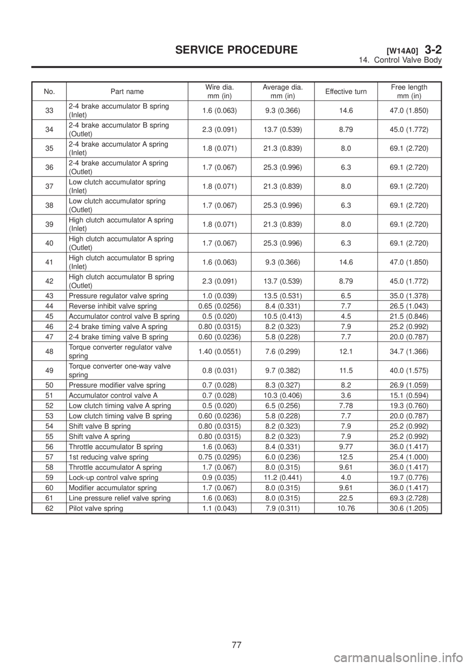
No. Part nameWire dia.
mm (in)Average dia.
mm (in)Effective turnFree length
mm (in)
332-4 brake accumulator B spring
(Inlet)1.6 (0.063) 9.3 (0.366) 14.6 47.0 (1.850)
342-4 brake accumulator B spring
(Outlet)2.3 (0.091) 13.7 (0.539) 8.79 45.0 (1.772)
352-4 brake accumulator A spring
(Inlet)1.8 (0.071) 21.3 (0.839) 8.0 69.1 (2.720)
362-4 brake accumulator A spring
(Outlet)1.7 (0.067) 25.3 (0.996) 6.3 69.1 (2.720)
37Low clutch accumulator spring
(Inlet)1.8 (0.071) 21.3 (0.839) 8.0 69.1 (2.720)
38Low clutch accumulator spring
(Outlet)1.7 (0.067) 25.3 (0.996) 6.3 69.1 (2.720)
39High clutch accumulator A spring
(Inlet)1.8 (0.071) 21.3 (0.839) 8.0 69.1 (2.720)
40High clutch accumulator A spring
(Outlet)1.7 (0.067) 25.3 (0.996) 6.3 69.1 (2.720)
41High clutch accumulator B spring
(Inlet)1.6 (0.063) 9.3 (0.366) 14.6 47.0 (1.850)
42High clutch accumulator B spring
(Outlet)2.3 (0.091) 13.7 (0.539) 8.79 45.0 (1.772)
43 Pressure regulator valve spring 1.0 (0.039) 13.5 (0.531) 6.5 35.0 (1.378)
44 Reverse inhibit valve spring 0.65 (0.0256) 8.4 (0.331) 7.7 26.5 (1.043)
45 Accumulator control valve B spring 0.5 (0.020) 10.5 (0.413) 4.5 21.5 (0.846)
46 2-4 brake timing valve A spring 0.80 (0.0315) 8.2 (0.323) 7.9 25.2 (0.992)
47 2-4 brake timing valve B spring 0.60 (0.0236) 5.8 (0.228) 7.7 20.0 (0.787)
48Torque converter regulator valve
spring1.40 (0.0551) 7.6 (0.299) 12.1 34.7 (1.366)
49Torque converter one-way valve
spring0.8 (0.031) 9.7 (0.382) 11.5 40.0 (1.575)
50 Pressure modifier valve spring 0.7 (0.028) 8.3 (0.327) 8.2 26.9 (1.059)
51 Accumulator control valve A 0.7 (0.028) 10.3 (0.406) 3.6 15.1 (0.594)
52 Low clutch timing valve A spring 0.5 (0.020) 6.5 (0.256) 7.78 19.3 (0.760)
53 Low clutch timing valve B spring 0.60 (0.0236) 5.8 (0.228) 7.7 20.0 (0.787)
54 Shift valve B spring 0.80 (0.0315) 8.2 (0.323) 7.9 25.2 (0.992)
55 Shift valve A spring 0.80 (0.0315) 8.2 (0.323) 7.9 25.2 (0.992)
56 Throttle accumulator B spring 1.6 (0.063) 8.4 (0.331) 9.77 36.0 (1.417)
57 1st reducing valve spring 0.75 (0.0295) 6.0 (0.236) 12.5 25.4 (1.000)
58 Throttle accumulator A spring 1.7 (0.067) 8.0 (0.315) 9.61 36.0 (1.417)
59 Lock-up control valve spring 0.9 (0.035) 11.2 (0.441) 4.0 19.7 (0.776)
60 Modifier accumulator spring 1.7 (0.067) 8.0 (0.315) 9.61 36.0 (1.417)
61 Line pressure relief valve spring 1.6 (0.063) 8.0 (0.315) 22.5 69.3 (2.728)
62 Pilot valve spring 1.1 (0.043) 7.9 (0.311) 10.76 30.6 (1.205)
77
[W14A0]3-2SERVICE PROCEDURE
14. Control Valve Body
Page 607 of 1456
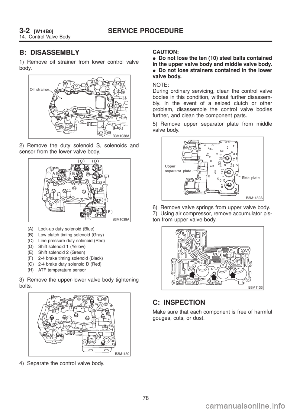
B: DISASSEMBLY
1) Remove oil strainer from lower control valve
body.
B3M1038A
2) Remove the duty solenoid S, solenoids and
sensor from the lower valve body.
B3M1039A
(A) Lock-up duty solenoid (Blue)
(B) Low clutch timing solenoid (Gray)
(C) Line pressure duty solenoid (Red)
(D) Shift solenoid 1 (Yellow)
(E) Shift solenoid 2 (Green)
(F) 2-4 brake timing solenoid (Black)
(G) 2-4 brake duty solenoid D (Red)
(H) ATF temperature sensor
3) Remove the upper-lower valve body tightening
bolts.
B3M1130
4) Separate the control valve body.CAUTION:
IDo not lose the ten (10) steel balls contained
in the upper valve body and middle valve body.
IDo not lose strainers contained in the lower
valve body.
NOTE:
During ordinary servicing, clean the control valve
bodies in this condition, without further disassem-
bly. In the event of a seized clutch or other
problem, disassemble the control valve bodies
further, and clean the component parts.
5) Remove upper separator plate from middle
valve body.
B3M1132A
6) Remove valve springs from upper valve body.
7) Using air compressor, remove accumulator pis-
ton from upper valve body.
B3M1133
C: INSPECTION
Make sure that each component is free of harmful
gouges, cuts, or dust.
78
3-2[W14B0]SERVICE PROCEDURE
14. Control Valve Body
Page 608 of 1456
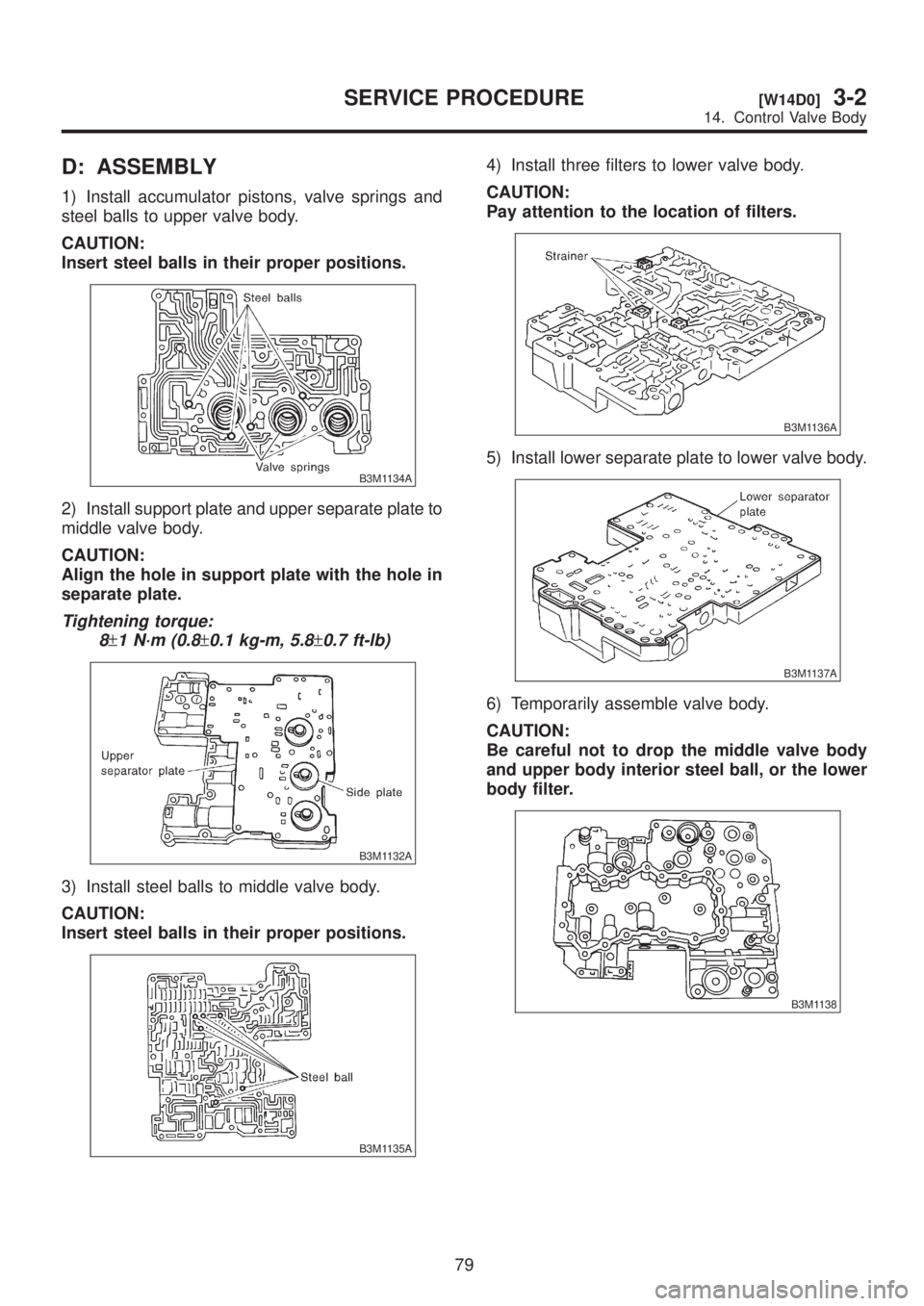
D: ASSEMBLY
1) Install accumulator pistons, valve springs and
steel balls to upper valve body.
CAUTION:
Insert steel balls in their proper positions.
B3M1134A
2) Install support plate and upper separate plate to
middle valve body.
CAUTION:
Align the hole in support plate with the hole in
separate plate.
Tightening torque:
8
±1 N´m (0.8±0.1 kg-m, 5.8±0.7 ft-lb)
B3M1132A
3) Install steel balls to middle valve body.
CAUTION:
Insert steel balls in their proper positions.
B3M1135A
4) Install three filters to lower valve body.
CAUTION:
Pay attention to the location of filters.
B3M1136A
5) Install lower separate plate to lower valve body.
B3M1137A
6) Temporarily assemble valve body.
CAUTION:
Be careful not to drop the middle valve body
and upper body interior steel ball, or the lower
body filter.
B3M1138
79
[W14D0]3-2SERVICE PROCEDURE
14. Control Valve Body
Page 609 of 1456
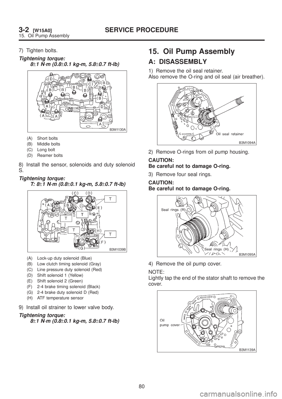
7) Tighten bolts.
Tightening torque:
8
±1 N´m (0.8±0.1 kg-m, 5.8±0.7 ft-lb)
B3M1130A
(A) Short bolts
(B) Middle bolts
(C) Long bolt
(D) Reamer bolts
8) Install the sensor, solenoids and duty solenoid
S.
Tightening torque:
T: 8
±1 N´m (0.8±0.1 kg-m, 5.8±0.7 ft-lb)
B3M1039B
(A) Lock-up duty solenoid (Blue)
(B) Low clutch timing solenoid (Gray)
(C) Line pressure duty solenoid (Red)
(D) Shift solenoid 1 (Yellow)
(E) Shift solenoid 2 (Green)
(F) 2-4 brake timing solenoid (Black)
(G) 2-4 brake duty solenoid D (Red)
(H) ATF temperature sensor
9) Install oil strainer to lower valve body.
Tightening torque:
8
±1 N´m (0.8±0.1 kg-m, 5.8±0.7 ft-lb)
15. Oil Pump Assembly
A: DISASSEMBLY
1) Remove the oil seal retainer.
Also remove the O-ring and oil seal (air breather).
B3M1094A
2) Remove O-rings from oil pump housing.
CAUTION:
Be careful not to damage O-ring.
3) Remove four seal rings.
CAUTION:
Be careful not to damage O-ring.
B3M1095A
4) Remove the oil pump cover.
NOTE:
Lightly tap the end of the stator shaft to remove the
cover.
B3M1139A
80
3-2[W15A0]SERVICE PROCEDURE
15. Oil Pump Assembly
Page 610 of 1456
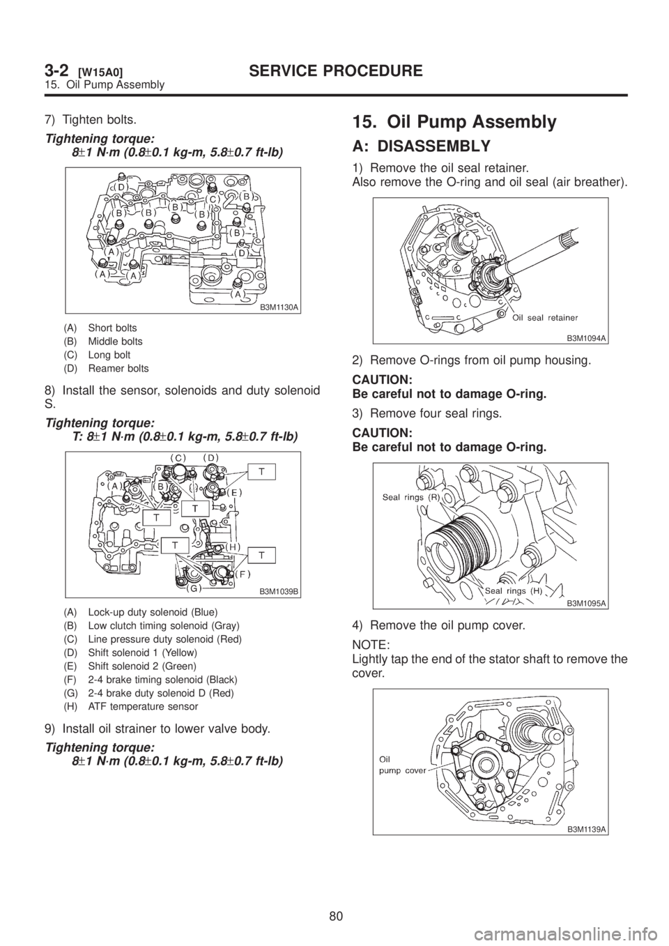
7) Tighten bolts.
Tightening torque:
8
±1 N´m (0.8±0.1 kg-m, 5.8±0.7 ft-lb)
B3M1130A
(A) Short bolts
(B) Middle bolts
(C) Long bolt
(D) Reamer bolts
8) Install the sensor, solenoids and duty solenoid
S.
Tightening torque:
T: 8
±1 N´m (0.8±0.1 kg-m, 5.8±0.7 ft-lb)
B3M1039B
(A) Lock-up duty solenoid (Blue)
(B) Low clutch timing solenoid (Gray)
(C) Line pressure duty solenoid (Red)
(D) Shift solenoid 1 (Yellow)
(E) Shift solenoid 2 (Green)
(F) 2-4 brake timing solenoid (Black)
(G) 2-4 brake duty solenoid D (Red)
(H) ATF temperature sensor
9) Install oil strainer to lower valve body.
Tightening torque:
8
±1 N´m (0.8±0.1 kg-m, 5.8±0.7 ft-lb)
15. Oil Pump Assembly
A: DISASSEMBLY
1) Remove the oil seal retainer.
Also remove the O-ring and oil seal (air breather).
B3M1094A
2) Remove O-rings from oil pump housing.
CAUTION:
Be careful not to damage O-ring.
3) Remove four seal rings.
CAUTION:
Be careful not to damage O-ring.
B3M1095A
4) Remove the oil pump cover.
NOTE:
Lightly tap the end of the stator shaft to remove the
cover.
B3M1139A
80
3-2[W15A0]SERVICE PROCEDURE
15. Oil Pump Assembly