driver SUBARU OUTBACK 2010 5.G Owners Manual
[x] Cancel search | Manufacturer: SUBARU, Model Year: 2010, Model line: OUTBACK, Model: SUBARU OUTBACK 2010 5.GPages: 448, PDF Size: 7.36 MB
Page 396 of 448
11-60Maintenance and service
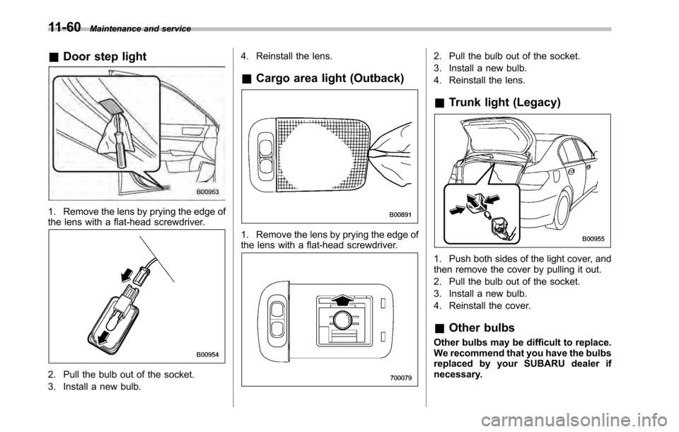
& Door step light
1. Remove the lens by prying the edge of
the lens with a flat-head screwdriver.
2. Pull the bulb out of the socket.
3. Install a new bulb. 4. Reinstall the lens.
& Cargo area light (Outback)
1. Remove the lens by prying the edge of
the lens with a flat-head screwdriver.
2. Pull the bulb out of the socket.
3. Install a new bulb.
4. Reinstall the lens. &Trunk light (Legacy)
1. Push both sides of the light cover, and
then remove the cover by pulling it out.
2. Pull the bulb out of the socket.
3. Install a new bulb.
4. Reinstall the cover. &Other bulbs
Other bulbs may be difficult to replace.
We recommend that you have the bulbs
replaced by your SUBARU dealer if
necessary.
Page 402 of 448
12-6Specifications
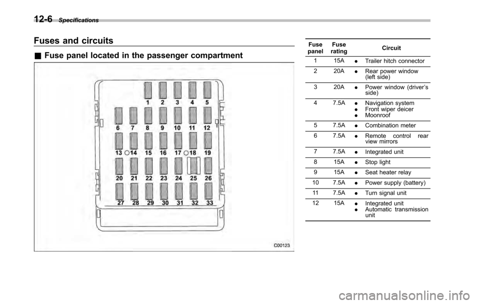
Fuses and circuits &Fuse panel located in the passenger compartmentFuse
panel Fuse
rating Circuit
1 15A .Trailer hitch connector
2 20A .Rear power window
(left side)
3 20A .Power window (driver ’s
side)
4 7.5A .Navigation system
. Front wiper deicer
. Moonroof
5 7.5A .Combination meter
6 7.5A .Remote control rear
view mirrors
7 7.5A .Integrated unit
8 15A .Stop light
9 15A .Seat heater relay
10 7.5A .Power supply (battery)
11 7.5A .Turn signal unit
12 15A .Integrated unit
. Automatic transmission
unit
Page 416 of 448

13-6Consumer information and Reporting safety defects
! Vehicle placard
The vehicle placard is affixed to the driver ’s side B-pillar.
Example:
U.S.-spec. models
Canada-spec. models
The vehicle placard shows original
tire size, recommended cold tire
inflation pressure on each tire at
maximum loaded vehicle weight,
seating capacity and loading infor-mation. ! Adverse safety consequences
of under-inflation
Driving at high speeds with exces-
sively low tire pressures can cause
the tires to flex severely and to
rapidly become hot. A sharp in-
crease in temperature could cause
tread separation, and failure of the
tire(s). Possible resulting loss of vehicle control could lead to anaccident.
! Measuring and adjusting air
pressure to achieve proper in- flation
Check and, if necessary, adjust the
pressure of each tire (including the
spare) at least once a month and
before any long journey. Check the
tire pressures when the tires are
cold. Use a pressure gauge to
adjust the tire pressures to the
specific values. Driving even a
short distance warms up the tires
and increases the tire pressures.
Also, the tire pressures are affected
by the outside temperature. It is
best to check tire pressure out-
doors before driving the vehicle.
When a tire becomes warm, the air
inside it expands, causing the tire
pressure to increase. Be careful not
to mistakenly release air from a
warm tire to reduce its pressure.
Page 421 of 448

&Tire care –maintenance and
safety practices
. Check on a daily basis that the
tires are free from serious damage,
nails, and stones. At the same time,
check the tires for abnormal wear.
. Inspect the tire tread regularly
and replace the tires before their
tread wear indicators become visi-
ble. When a tire ’streadwear
indicator becomes visible, the tire
is worn beyond the acceptable limit
and must be replaced immediately.
With a tire in this condition, driving
at even low speeds in wet weather
can cause the vehicle to hydro-
plane. Possible resulting loss of
vehiclecontrolcanleadtoanaccident.
. To maximize the life of each tire
and ensure that the tires wear
uniformly, it is best to rotate the
tires every 7,500 miles (12,000 km).
Rotating the tires involves switch-
ing the front and rear tires on the
right-hand side of the vehicle and
similarly switching the front and rear tires on the left-hand side of
the vehicle. (Each tire must be kept
on its original side of the vehicle.)
Replace any damaged or unevenly
worn tire at the time of rotation.
After tire rotation, adjust the tire
pressures and make sure the wheel
nuts are correctly tightened. For
information about the tightening
torque and tightening sequence
for the wheel nuts, refer to
“Flat
tires ”F 9-6 .
& Vehicle load limit –how to
determine
The load capacity of your vehicle is
determined by weight, not by avail-
able cargo space. The load limit of
your vehicle is shown on the
vehicle placard attached to the
driver ’s side B-pillar. Locate the
statement “The combined weight
of occupants and cargo should
never exceed XXX kg or XXX lbs ”
on your vehicle ’s placard.
Thevehicleplacardalsoshows
seating capacity of your vehicle. The total load capacity includes the
total weight of driver and all pas-
sengers and their belongings, any
cargo, any optional equipment such
as a trailer hitch, roof rack or bike
carrier, etc., and the tongue load of
a trailer. Therefore cargo capacity
can be calculated by the following method.
Cargo capacity = Load limit
(total
weight of occupants + total weight
of optional equipment + tongue
load of a trailer (if applicable))
For towing capacity information and
weight limits, refer to “Trailer tow-
ing ”F 8-19 .
Consumer information and Reporting safety defects
13-11
– CONTINUED –
Page 424 of 448

13-14Consumer information and Reporting safety defects
vehicle (bringing the number of
occupants to three), and a child
restraint system weighing 11 lbs (5
kg) is installed in the vehicle for the
child to use, the calculations are asfollows: 1. Calculate the total weight.
2.Calculate the available load ca-
pacity.
3. The total weight now exceeds
the capacity weight by 22 lbs (10
kg), so the cargo weight must be
reduced by 22 lbs (10 kg) or more.
& Determining compatibility of
tire and vehicle load capaci-ties
The sum of four tires ’maximum
load ratings must exceed the max-
imum loaded vehicle weight( “ GVWR ”). In addition, sum of the
maximum load ratings of two front
tires and of two rear tires must
exceed each axle ’smaximum
loaded capacity ( “GAWR ”). Original
equipment tires are designed to
fulfill those conditions.
The maximum loaded vehicle
weight is referred to Gross Vehicle
Weight Rating (GVWR). And each axle
’s maximum loaded capacity is
referred to Gross Axle Weight Rat-
ing (GAWR). The GVWR and each axle ’s GAWR are shown on the
vehicle certification label affixed to
the driver ’s door.
The GVWR and front and rear
GAWRs are determined by not only
the maximum load rating of tires but
also loaded capacities of the vehi-cle ’s suspension, axles and other
parts of the body.
Therefore, this means that the
vehicle cannot necessarily be
loaded up to the tire ’s maximum
load rating on the tire sidewall.
& Adverse safety conse-
quences of overloading on
handling and stopping and
on tires
Overloading could affect vehicle
handling, stopping distance, vehicle
and tire as shown in the following.
This could lead to an accident and
possibly result in severe personal
injury.
Page 425 of 448

.Vehicle stability will deteriorate.
. Heavy and/or high-mounted
loads could increase the risk of
rollover.
. Stopping distance will increase.
. Brakes could overheat and fail.
. Suspension, bearings, axles and
other parts of the body could break
or experience accelerated wear
that will shorten vehicle life.
. Tires could fail.
. Tread separation could occur.
. Tire could separate from its rim.
& Steps for Determining Cor-
rect Load Limit
1. Locate the statement “The com-
bined weight of occupants and
cargo should never exceed XXXpounds ”on your vehicle ’s placard.
2. Determine the combined weight
of the driver and passengers that
will be riding in your vehicle.
3. Subtract the combined weight of
the driver and passengers from
XXX kilograms or XXX pounds.
4. The resulting figure equals the available amount of cargo and
luggage load capacity. For exam-
ple, if the
“XXX ”amount equals
1,400 lbs (635 kg) and there will be
five- 150 lbs (68 kg) passengers in
your vehicle, the amount of avail-
able cargo and luggage load capa-
city is 650 lbs (1,400 750 (5 6
150) = 650 lbs).
5. Determine the combined weight
of luggage and cargo being loaded
on the vehicle. That weight may not
safely exceed the available cargo
and luggage load capacity calcu-
lated in Step 4.
6. If your vehicle will be towing a
trailer, load from your trailer will be
transferred to your vehicle. Consult
this manual to determine how this
reduces the available cargo and
luggage load capacity of your ve-hicle. Uniform tire quality grading
standards
This information indicates the rela-
tive performance of passenger car
tires in the area of treadwear,
traction, and temperature resis-
tance. This is to aid the consumer
in making an informed choice in the
purchase of tires.
Quality grades can be found where
applicable on the tire sidewall be-
tween tread shoulder and maxi-
mum section width. For example:
Treadwear 200 Traction AA Tem-
perature A
The quality grades apply to new
pneumatic tires for use on passen-
ger cars. However, they do not
apply to deep tread, winter type
snow tires, space-saver or tempor-
ary use spare tires, tires with
nominal rim diameters of 12 inches
or less, or to some limited produc-
tion tires.
All passenger car tires must con-
Consumer information and Reporting safety defects
13-15
– CONTINUED –
Page 433 of 448

Electrical system........................................................ 12-3
Electronic Brake Force Distribution (EBD) system ........................................................... 3-18, 7-26
Electronic parking brake. ............................................. 7-34
Automatic release function by gas pedal ................... 7-35
Hill Holder ............................................................. 7-35
Warning ........................................................ 3-19, 7-37
Emergency Locking Retractor (ELR) ............................. 1-13
Engine
Compartment overview ........................................... 11-9
Coolant ................................................................ 11-18
Exhaust gas (carbon monoxide) ............................. 6, 8-2
Hood .................................................................... 11-7
Low oil level warning light ....................................... 3-14
Oil....................................................................... 11-12 Overheating .......................................................... 9-12
Starting ................................................................... 7-8
Stopping ............................................................... 7-10
Exterior care .............................................................. 10-2
F
Flat tires ..................................................................... 9-6
Floor mat .................................................................. 6-14
Fluid level
Automatic transmission .......................................... 11-24
Brake .................................................................. 11-30
Clutch .................................................................. 11-31
Power steering ..................................................... 11-29
Fog light Bulb .................................................................... 11-53
Indicator light ......................................................... 3-23 Switch
................................................................... 3-30
Front Differential gear oil ................................................ 11-26
Fog light ...................................................... 3-30, 11-53
Fog light indicator light ............................................ 3-23
Position light ........................................................ 11-53
Seatbelt pretensioners ............................................ 1-22
Turn signal light .................................................... 11-53
Front seats ................................................................. 1-2
Forward and backward adjustment ............................ 1-3
Power seat ............................................................. 1-4
Reclining ................................................................ 1-3
Seat height adjustment (driver ’s seat) ........................ 1-4
Fuel ........................................................................... 7-2
Economy hints ........................................................ 8-2
Filler lid and cap ...................................................... 7-3
Gauge .................................................................... 3-7
Requirements ......................................................... 7-2
Fuses ..................................................................... 11-48
Main fuse ............................................................ 11-50
Fuses and circuits ...................................................... 12-6
G
GAWR (Gross Axle Weight Rating) .. ............................. 8-13
Glove box ................................................................... 6-6
GVWR (Gross Vehicle Weight Rating) ........................... 8-13
H
Hands-free system. ..................................................... 5-32
Hazard warning flasher .......................................... 3-5, 9-2
Head restraint adjustment Index
14-5