SUBARU TRIBECA 2009 1.G Service Workshop Manual
Manufacturer: SUBARU, Model Year: 2009, Model line: TRIBECA, Model: SUBARU TRIBECA 2009 1.GPages: 2453, PDF Size: 46.32 MB
Page 1481 of 2453
EN(H6DO)(diag)-320
Diagnostic Procedure with Diagnostic Trouble Code (DTC)
ENGINE (DIAGNOSTICS)
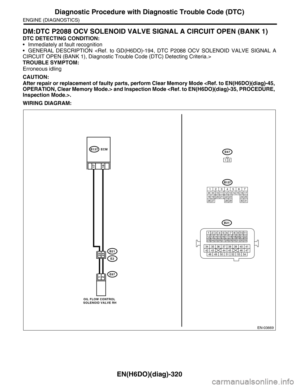
DM:DTC P2088 OCV SOLENOID VALVE SIGNAL A CIRCUIT OPEN (BANK 1)
DTC DETECTING CONDITION:
•Immediately at fault recognition
•GENERAL DESCRIPTION
TROUBLE SYMPTOM:
Erroneous idling
CAUTION:
After repair or replacement of faulty parts, perform Clear Memory Mode
WIRING DIAGRAM:
EN-03669
B21
E2
B137
E67
16
21
2423
E67
12
17
ECM
B21
123412131415567816171819910 1120212223 24 25 2627 28 29 3031 32 33
3534 37363938 41404342 4445 47464948 51505352 54
OIL FLOW CONTROL SOLENOID VALVE RH
B137
85610 11 12 13 14 157213416
3019 20 2228 29
91718 2521 23 243126 27
Page 1482 of 2453
EN(H6DO)(diag)-321
Diagnostic Procedure with Diagnostic Trouble Code (DTC)
ENGINE (DIAGNOSTICS)
Step Check Yes No
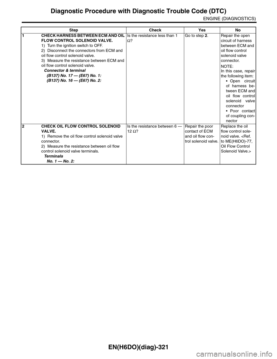
1CHECK HARNESS BETWEEN ECM AND OIL
FLOW CONTROL SOLENOID VALVE.
1) Turn the ignition switch to OFF.
2) Disconnect the connectors from ECM and
oil flow control solenoid valve.
3) Measure the resistance between ECM and
oil flow control solenoid valve.
Connector & terminal
(B137) No. 17 — (E67) No. 1:
(B137) No. 16 — (E67) No. 2:
Is the resistance less than 1
Ω?
Go to step 2.Repair the open
circuit of harness
between ECM and
oil flow control
solenoid valve
connector.
NOTE:In this case, repair
the following item:
•Open circuit
of harness be-
tween ECM and
oil flow control
solenoid valve
connector
•Poor contact
of coupling con-
nector
2CHECK OIL FLOW CONTROL SOLENOID
VALVE.
1) Remove the oil flow control solenoid valve
connector.
2) Measure the resistance between oil flow
control solenoid valve terminals.
Te r m i n a l s
No. 1 — No. 2:
Is the resistance between 6 —
12 Ω?
Repair the poor
contact of ECM
and oil flow con-
trol solenoid valve.
Replace the oil
flow control sole-
noid valve.
Oil Flow Control
Solenoid Valve.>
Page 1483 of 2453
EN(H6DO)(diag)-322
Diagnostic Procedure with Diagnostic Trouble Code (DTC)
ENGINE (DIAGNOSTICS)
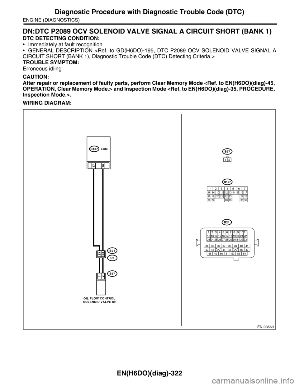
DN:DTC P2089 OCV SOLENOID VALVE SIGNAL A CIRCUIT SHORT (BANK 1)
DTC DETECTING CONDITION:
•Immediately at fault recognition
•GENERAL DESCRIPTION
TROUBLE SYMPTOM:
Erroneous idling
CAUTION:
After repair or replacement of faulty parts, perform Clear Memory Mode
WIRING DIAGRAM:
EN-03669
B21
E2
B137
E67
16
21
2423
E67
12
17
ECM
B21
123412131415567816171819910 1120212223 24 25 2627 28 29 3031 32 33
3534 37363938 41404342 4445 47464948 51505352 54
OIL FLOW CONTROL SOLENOID VALVE RH
B137
85610 11 12 13 14 157213416
3019 20 2228 29
91718 2521 23 243126 27
Page 1484 of 2453
EN(H6DO)(diag)-323
Diagnostic Procedure with Diagnostic Trouble Code (DTC)
ENGINE (DIAGNOSTICS)
Step Check Yes No
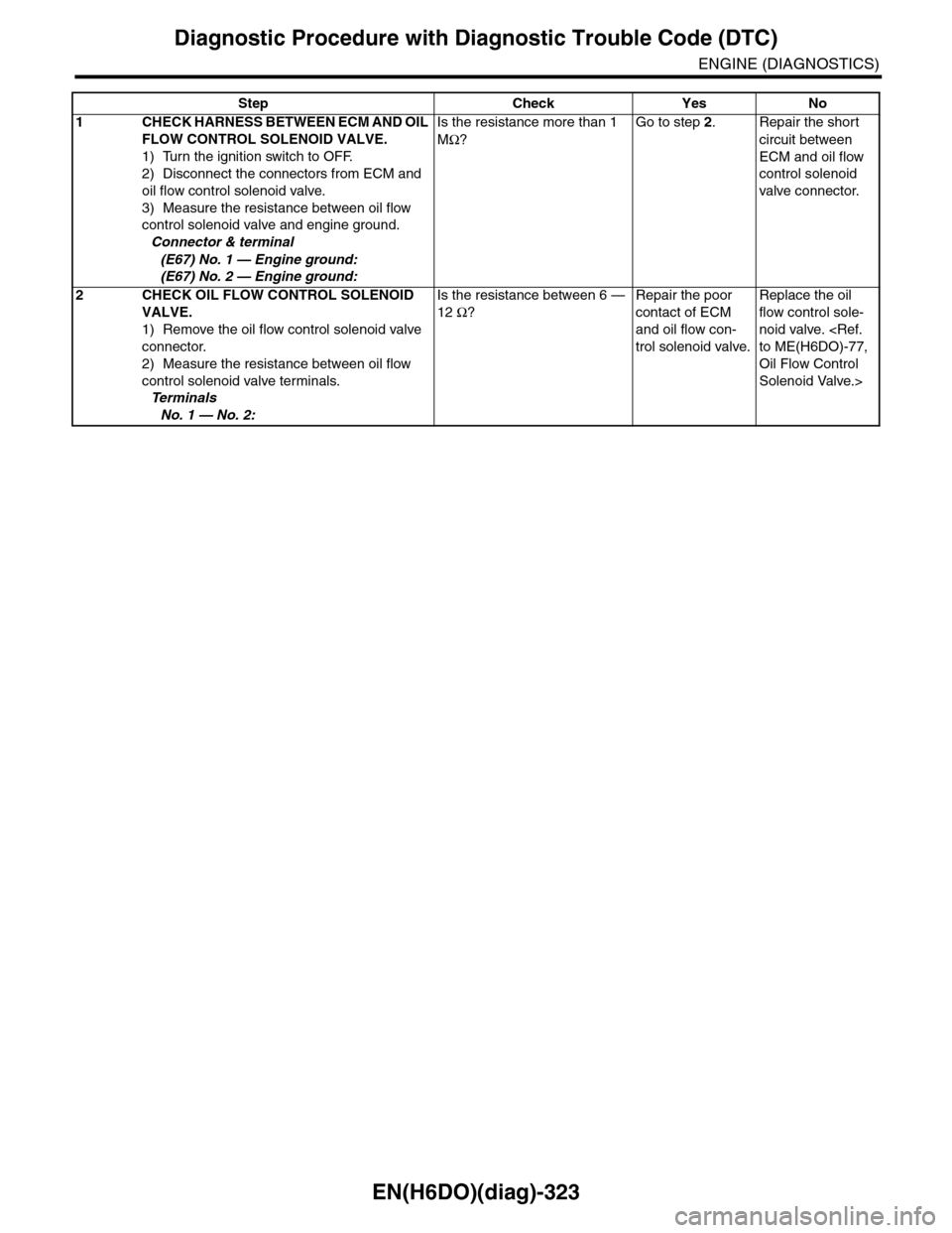
1CHECK HARNESS BETWEEN ECM AND OIL
FLOW CONTROL SOLENOID VALVE.
1) Turn the ignition switch to OFF.
2) Disconnect the connectors from ECM and
oil flow control solenoid valve.
3) Measure the resistance between oil flow
control solenoid valve and engine ground.
Connector & terminal
(E67) No. 1 — Engine ground:
(E67) No. 2 — Engine ground:
Is the resistance more than 1
MΩ?
Go to step 2.Repair the short
circuit between
ECM and oil flow
control solenoid
valve connector.
2CHECK OIL FLOW CONTROL SOLENOID
VALVE.
1) Remove the oil flow control solenoid valve
connector.
2) Measure the resistance between oil flow
control solenoid valve terminals.
Te r m i n a l s
No. 1 — No. 2:
Is the resistance between 6 —
12 Ω?
Repair the poor
contact of ECM
and oil flow con-
trol solenoid valve.
Replace the oil
flow control sole-
noid valve.
Oil Flow Control
Solenoid Valve.>
Page 1485 of 2453
EN(H6DO)(diag)-324
Diagnostic Procedure with Diagnostic Trouble Code (DTC)
ENGINE (DIAGNOSTICS)
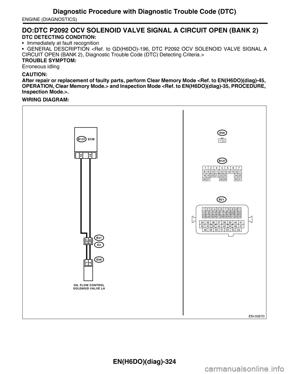
DO:DTC P2092 OCV SOLENOID VALVE SIGNAL A CIRCUIT OPEN (BANK 2)
DTC DETECTING CONDITION:
•Immediately at fault recognition
•GENERAL DESCRIPTION
TROUBLE SYMPTOM:
Erroneous idling
CAUTION:
After repair or replacement of faulty parts, perform Clear Memory Mode
WIRING DIAGRAM:
EN-03670
B21
E2
B137
E68
14
21
2827
E68
12
15
ECM
B21
123412131415567816171819910 1120212223 24 25 2627 28 29 3031 32 33
3534 37363938 41404342 4445 47464948 51505352 54
OIL FLOW CONTROLSOLENOID VALVE LH
B137
85610 11 12 13 14 157213416
3019 20 2228 29
91718 2521 23 243126 27
Page 1486 of 2453
EN(H6DO)(diag)-325
Diagnostic Procedure with Diagnostic Trouble Code (DTC)
ENGINE (DIAGNOSTICS)
Step Check Yes No
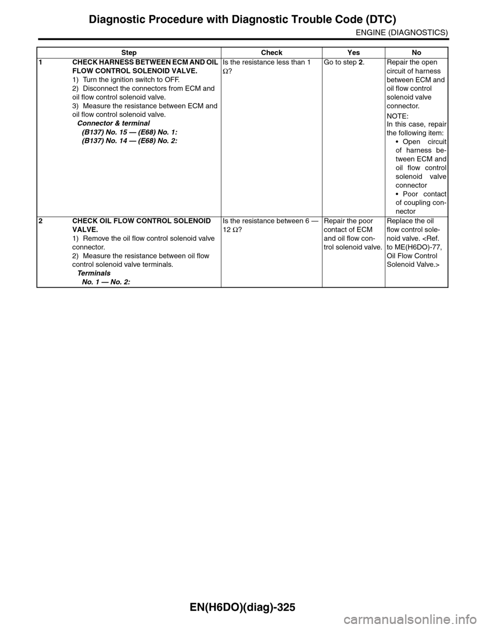
1CHECK HARNESS BETWEEN ECM AND OIL
FLOW CONTROL SOLENOID VALVE.
1) Turn the ignition switch to OFF.
2) Disconnect the connectors from ECM and
oil flow control solenoid valve.
3) Measure the resistance between ECM and
oil flow control solenoid valve.
Connector & terminal
(B137) No. 15 — (E68) No. 1:
(B137) No. 14 — (E68) No. 2:
Is the resistance less than 1
Ω?
Go to step 2.Repair the open
circuit of harness
between ECM and
oil flow control
solenoid valve
connector.
NOTE:In this case, repair
the following item:
•Open circuit
of harness be-
tween ECM and
oil flow control
solenoid valve
connector
•Poor contact
of coupling con-
nector
2CHECK OIL FLOW CONTROL SOLENOID
VALVE.
1) Remove the oil flow control solenoid valve
connector.
2) Measure the resistance between oil flow
control solenoid valve terminals.
Te r m i n a l s
No. 1 — No. 2:
Is the resistance between 6 —
12 Ω?
Repair the poor
contact of ECM
and oil flow con-
trol solenoid valve.
Replace the oil
flow control sole-
noid valve.
Oil Flow Control
Solenoid Valve.>
Page 1487 of 2453
EN(H6DO)(diag)-326
Diagnostic Procedure with Diagnostic Trouble Code (DTC)
ENGINE (DIAGNOSTICS)
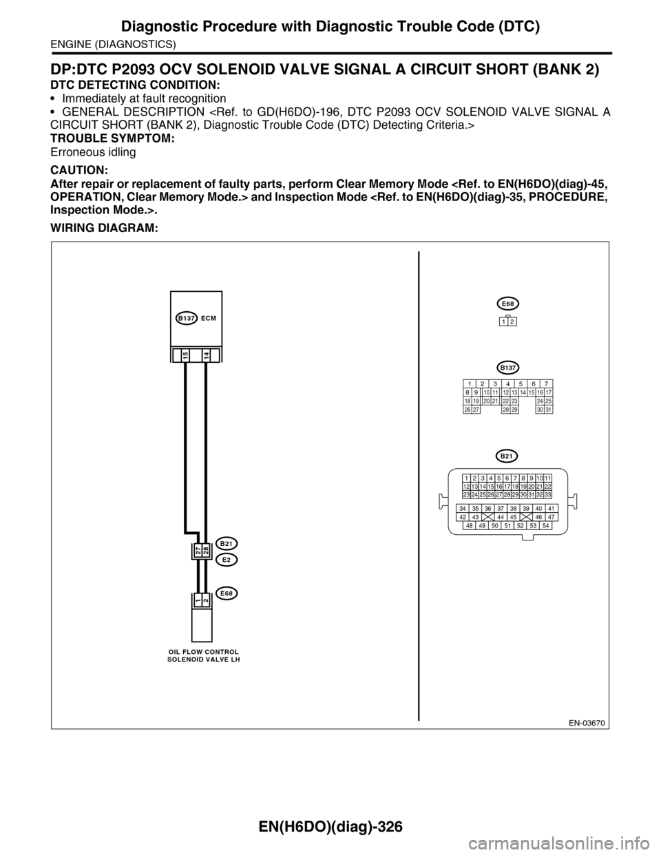
DP:DTC P2093 OCV SOLENOID VALVE SIGNAL A CIRCUIT SHORT (BANK 2)
DTC DETECTING CONDITION:
•Immediately at fault recognition
•GENERAL DESCRIPTION
TROUBLE SYMPTOM:
Erroneous idling
CAUTION:
After repair or replacement of faulty parts, perform Clear Memory Mode
WIRING DIAGRAM:
EN-03670
B21
E2
B137
E68
14
21
2827
E68
12
15
ECM
B21
123412131415567816171819910 1120212223 24 25 2627 28 29 3031 32 33
3534 37363938 41404342 4445 47464948 51505352 54
OIL FLOW CONTROLSOLENOID VALVE LH
B137
85610 11 12 13 14 157213416
3019 20 2228 29
91718 2521 23 243126 27
Page 1488 of 2453
EN(H6DO)(diag)-327
Diagnostic Procedure with Diagnostic Trouble Code (DTC)
ENGINE (DIAGNOSTICS)
Step Check Yes No
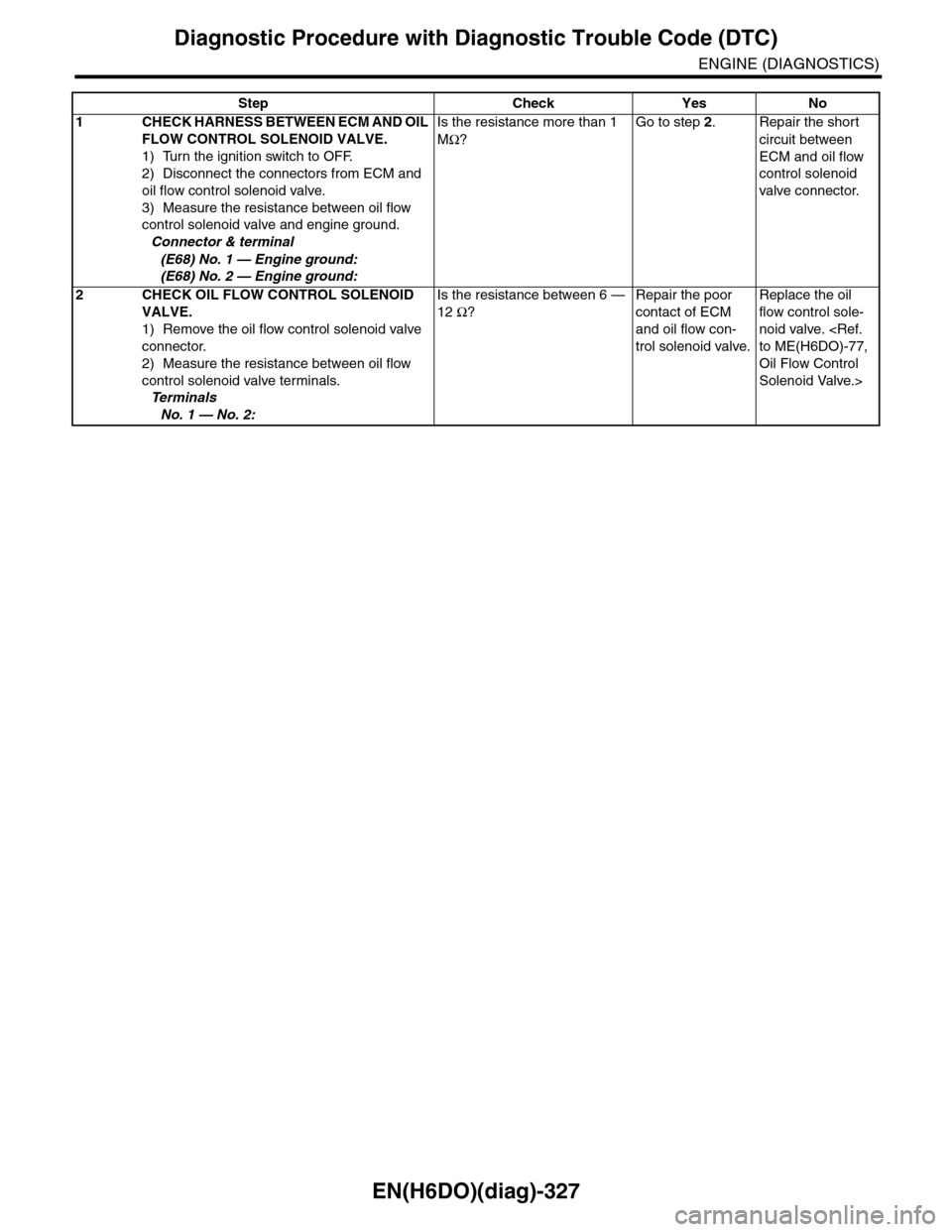
1CHECK HARNESS BETWEEN ECM AND OIL
FLOW CONTROL SOLENOID VALVE.
1) Turn the ignition switch to OFF.
2) Disconnect the connectors from ECM and
oil flow control solenoid valve.
3) Measure the resistance between oil flow
control solenoid valve and engine ground.
Connector & terminal
(E68) No. 1 — Engine ground:
(E68) No. 2 — Engine ground:
Is the resistance more than 1
MΩ?
Go to step 2.Repair the short
circuit between
ECM and oil flow
control solenoid
valve connector.
2CHECK OIL FLOW CONTROL SOLENOID
VALVE.
1) Remove the oil flow control solenoid valve
connector.
2) Measure the resistance between oil flow
control solenoid valve terminals.
Te r m i n a l s
No. 1 — No. 2:
Is the resistance between 6 —
12 Ω?
Repair the poor
contact of ECM
and oil flow con-
trol solenoid valve.
Replace the oil
flow control sole-
noid valve.
Oil Flow Control
Solenoid Valve.>
Page 1489 of 2453
EN(H6DO)(diag)-328
Diagnostic Procedure with Diagnostic Trouble Code (DTC)
ENGINE (DIAGNOSTICS)
DQ:DTC P2096 POST CATALYST FUEL TRIM SYSTEM TOO LEAN (BANK 1)
DTC DETECTING CONDITION:
•Detected when two consecutive driving cycles with fault occur.
•GENERAL DESCRIPTION
CAUTION:
After repair or replacement of faulty parts, perform Clear Memory Mode
Page 1490 of 2453
EN(H6DO)(diag)-329
Diagnostic Procedure with Diagnostic Trouble Code (DTC)
ENGINE (DIAGNOSTICS)
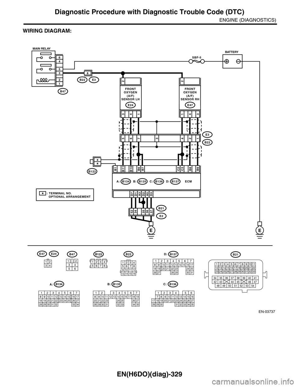
WIRING DIAGRAM:
EN-03737
SBF-5
B47
12
35
46
A3D1D7D2A5D3
2
3736353452B21
E2
ECM
B11B1B10B6B7C2C3B8B9
413
E24
2
431
E47
E3B22
8
56E3
B222134
B47
3456
12
B22
1234567891011 121314 15 16
3412
E47E24
B135
567821943102422 23 2511 12 13 14 1526 2728
16 17 18 1920 2129 30 31 32 33 34 35
B:
B21
123412131415567816171819910 1120212223 24 25 2627 28 29 3031 32 33
3534 37363938 41404342 4445 47464948 51505352 54
EE
B135B:B136C:B137D:B134A:
7
FRONTOXYGEN(A/F)SENSOR LH
FRONTOXYGEN(A/F)SENSOR RH
MAIN RELAYBATTERY
B136
16101112131415252430
9871718192028212223293231
123456
2726333435
C:
B137
85610 11 12 13 14 157213416
3019 20 2228 29
91718 2521 23 243126 27
D:B122
34561278
*: TERMINAL NO. OPTIONAL ARRANGEMENT
**
B122
A:B134
85610 11 12 13 14 157213416
3019 20 2228 29
91718252123 24323126 2733 34