SUBARU TRIBECA 2009 1.G Service Workshop Manual
Manufacturer: SUBARU, Model Year: 2009, Model line: TRIBECA, Model: SUBARU TRIBECA 2009 1.GPages: 2453, PDF Size: 46.32 MB
Page 1641 of 2453
GD(H6DO)-29
Diagnostic Trouble Code (DTC) Detecting Criteria
GENERAL DESCRIPTION
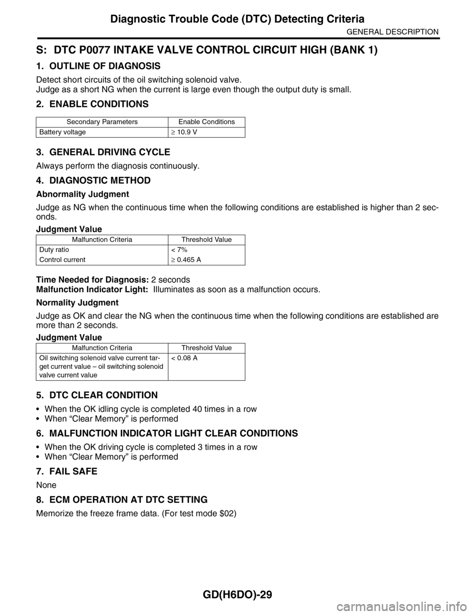
S: DTC P0077 INTAKE VALVE CONTROL CIRCUIT HIGH (BANK 1)
1. OUTLINE OF DIAGNOSIS
Detect short circuits of the oil switching solenoid valve.
Judge as a short NG when the current is large even though the output duty is small.
2. ENABLE CONDITIONS
3. GENERAL DRIVING CYCLE
Always perform the diagnosis continuously.
4. DIAGNOSTIC METHOD
Abnormality Judgment
Judge as NG when the continuous time when the following conditions are established is higher than 2 sec-
onds.
Time Needed for Diagnosis: 2 seconds
Malfunction Indicator Light: Illuminates as soon as a malfunction occurs.
Normality Judgment
Judge as OK and clear the NG when the continuous time when the following conditions are established are
more than 2 seconds.
5. DTC CLEAR CONDITION
•When the OK idling cycle is completed 40 times in a row
•When “Clear Memory” is performed
6. MALFUNCTION INDICATOR LIGHT CLEAR CONDITIONS
•When the OK driving cycle is completed 3 times in a row
•When “Clear Memory” is performed
7. FAIL SAFE
None
8. ECM OPERATION AT DTC SETTING
Memorize the freeze frame data. (For test mode $02)
Secondary Parameters Enable Conditions
Battery voltage≥ 10.9 V
Judgment Value
Malfunction Criteria Threshold Value
Duty ratio < 7%
Control current≥ 0.465 A
Judgment Value
Malfunction Criteria Threshold Value
Oil switching solenoid valve current tar-
get current value – oil switching solenoid
valve current value
< 0.08 A
Page 1642 of 2453
GD(H6DO)-30
Diagnostic Trouble Code (DTC) Detecting Criteria
GENERAL DESCRIPTION
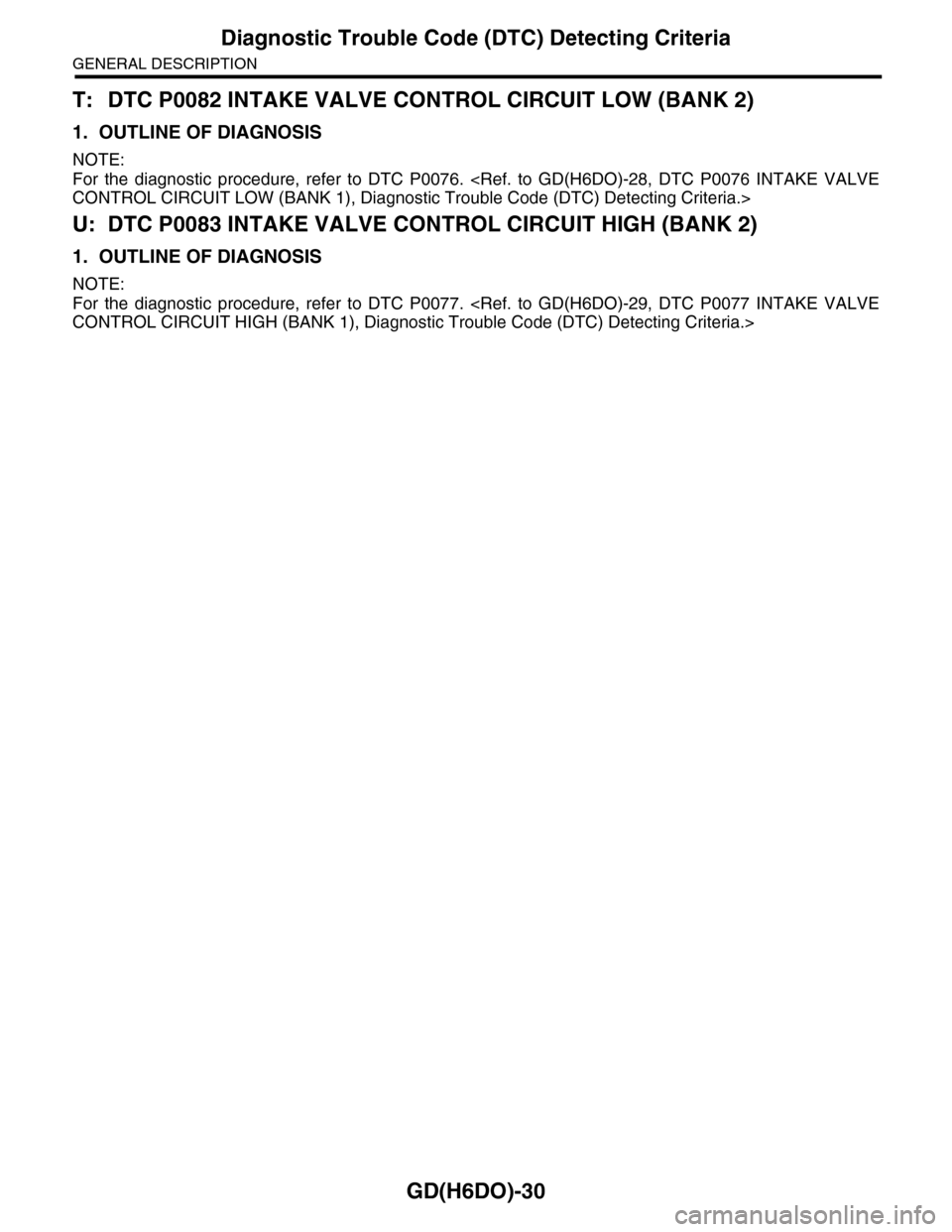
T: DTC P0082 INTAKE VALVE CONTROL CIRCUIT LOW (BANK 2)
1. OUTLINE OF DIAGNOSIS
NOTE:
For the diagnostic procedure, refer to DTC P0076.
U: DTC P0083 INTAKE VALVE CONTROL CIRCUIT HIGH (BANK 2)
1. OUTLINE OF DIAGNOSIS
NOTE:
For the diagnostic procedure, refer to DTC P0077.
Page 1643 of 2453
GD(H6DO)-31
Diagnostic Trouble Code (DTC) Detecting Criteria
GENERAL DESCRIPTION
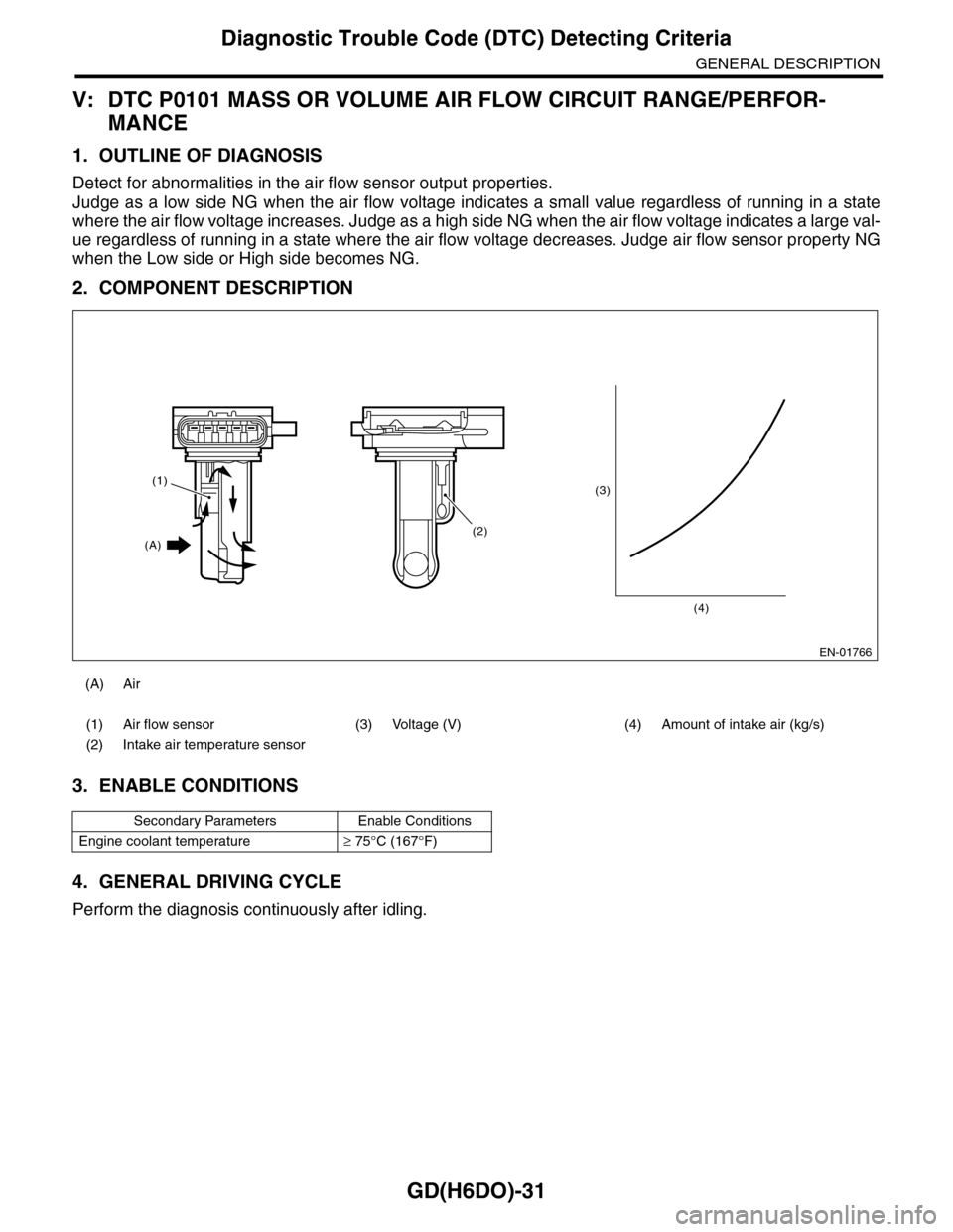
V: DTC P0101 MASS OR VOLUME AIR FLOW CIRCUIT RANGE/PERFOR-
MANCE
1. OUTLINE OF DIAGNOSIS
Detect for abnormalities in the air flow sensor output properties.
Judge as a low side NG when the air flow voltage indicates a small value regardless of running in a state
where the air flow voltage increases. Judge as a high side NG when the air flow voltage indicates a large val-
ue regardless of running in a state where the air flow voltage decreases. Judge air flow sensor property NG
when the Low side or High side becomes NG.
2. COMPONENT DESCRIPTION
3. ENABLE CONDITIONS
4. GENERAL DRIVING CYCLE
Perform the diagnosis continuously after idling.
(A) Air
(1) Air flow sensor (3) Voltage (V) (4) Amount of intake air (kg/s)
(2) Intake air temperature sensor
Secondary Parameters Enable Conditions
Engine coolant temperature≥ 75°C (167°F)
EN-01766
(3)
(4)
(2)
(1)
(A)
Page 1644 of 2453
GD(H6DO)-32
Diagnostic Trouble Code (DTC) Detecting Criteria
GENERAL DESCRIPTION
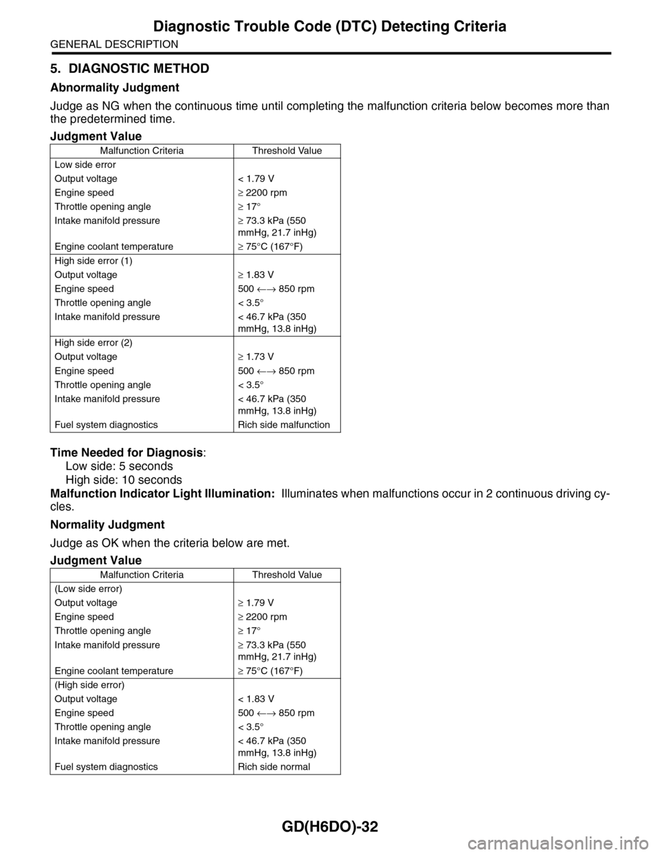
5. DIAGNOSTIC METHOD
Abnormality Judgment
Judge as NG when the continuous time until completing the malfunction criteria below becomes more than
the predetermined time.
Time Needed for Diagnosis:
Low side: 5 seconds
High side: 10 seconds
Malfunction Indicator Light Illumination: Illuminates when malfunctions occur in 2 continuous driving cy-
cles.
Normality Judgment
Judge as OK when the criteria below are met.
Judgment Value
Malfunction Criteria Threshold Value
Low side error
Output voltage < 1.79 V
Engine speed≥ 2200 rpm
Throttle opening angle≥ 17°
Intake manifold pressure≥ 73.3 kPa (550
mmHg, 21.7 inHg)
Engine coolant temperature≥ 75°C (167°F)
High side error (1)
Output voltage≥ 1.83 V
Engine speed 500 ←→ 850 rpm
Throttle opening angle < 3.5°
Intake manifold pressure < 46.7 kPa (350
mmHg, 13.8 inHg)
High side error (2)
Output voltage≥ 1.73 V
Engine speed 500 ←→ 850 rpm
Throttle opening angle < 3.5°
Intake manifold pressure < 46.7 kPa (350
mmHg, 13.8 inHg)
Fuel system diagnostics Rich side malfunction
Judgment Value
Malfunction Criteria Threshold Value
(Low side error)
Output voltage≥ 1.79 V
Engine speed≥ 2200 rpm
Throttle opening angle≥ 17°
Intake manifold pressure≥ 73.3 kPa (550
mmHg, 21.7 inHg)
Engine coolant temperature≥ 75°C (167°F)
(High side error)
Output voltage < 1.83 V
Engine speed 500 ←→ 850 rpm
Throttle opening angle < 3.5°
Intake manifold pressure < 46.7 kPa (350
mmHg, 13.8 inHg)
Fuel system diagnostics Rich side normal
Page 1645 of 2453
GD(H6DO)-33
Diagnostic Trouble Code (DTC) Detecting Criteria
GENERAL DESCRIPTION
6. DTC CLEAR CONDITION
•When the OK idling cycle is completed 40 times in a row
•When “Clear Memory” is performed
7. MALFUNCTION INDICATOR LIGHT CLEAR CONDITIONS
•When the OK driving cycle is completed 3 times in a row
•When “Clear Memory” is performed
8. FAIL SAFE
None
9. ECM OPERATION AT DTC SETTING
Memorize the freeze frame data. (For test mode $02)
Page 1646 of 2453
GD(H6DO)-34
Diagnostic Trouble Code (DTC) Detecting Criteria
GENERAL DESCRIPTION
W: DTC P0102 MASS OR VOLUME AIR FLOW CIRCUIT LOW INPUT
1. OUTLINE OF DIAGNOSIS
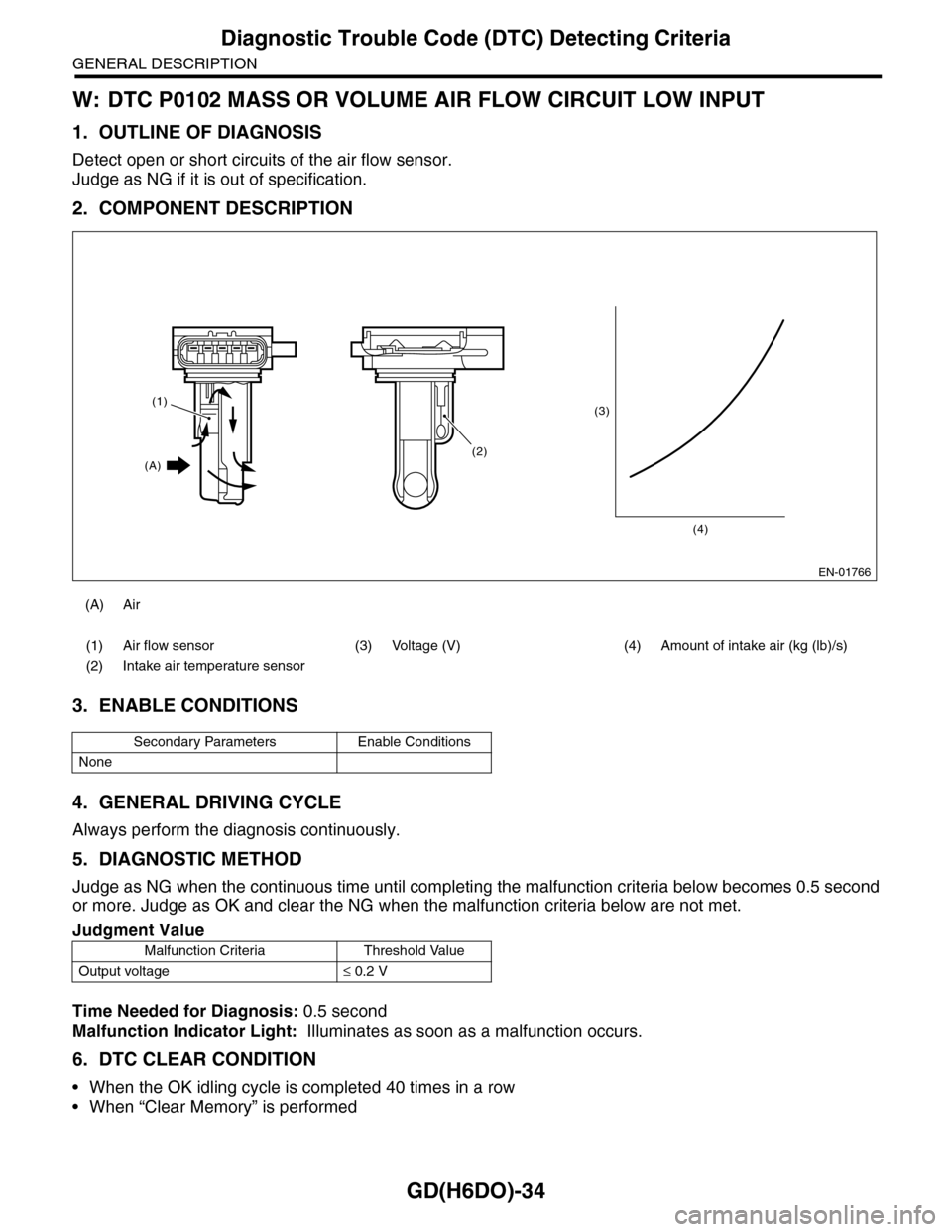
Detect open or short circuits of the air flow sensor.
Judge as NG if it is out of specification.
2. COMPONENT DESCRIPTION
3. ENABLE CONDITIONS
4. GENERAL DRIVING CYCLE
Always perform the diagnosis continuously.
5. DIAGNOSTIC METHOD
Judge as NG when the continuous time until completing the malfunction criteria below becomes 0.5 second
or more. Judge as OK and clear the NG when the malfunction criteria below are not met.
Time Needed for Diagnosis: 0.5 second
Malfunction Indicator Light: Illuminates as soon as a malfunction occurs.
6. DTC CLEAR CONDITION
•When the OK idling cycle is completed 40 times in a row
•When “Clear Memory” is performed
(A) Air
(1) Air flow sensor (3) Voltage (V) (4) Amount of intake air (kg (lb)/s)
(2) Intake air temperature sensor
Secondary Parameters Enable Conditions
None
Judgment Value
Malfunction Criteria Threshold Value
Output voltage≤ 0.2 V
EN-01766
(3)
(4)
(2)
(1)
(A)
Page 1647 of 2453
GD(H6DO)-35
Diagnostic Trouble Code (DTC) Detecting Criteria
GENERAL DESCRIPTION
7. MALFUNCTION INDICATOR LIGHT CLEAR CONDITIONS
•When the OK driving cycle is completed 3 times in a row
•When “Clear Memory” is performed
8. FAIL SAFE
Purge control: Not allowed to purge
9. ECM OPERATION AT DTC SETTING
Memorize the freeze frame data. (For test mode $02)
Page 1648 of 2453
GD(H6DO)-36
Diagnostic Trouble Code (DTC) Detecting Criteria
GENERAL DESCRIPTION
X: DTC P0103 MASS OR VOLUME AIR FLOW CIRCUIT HIGH INPUT
1. OUTLINE OF DIAGNOSIS
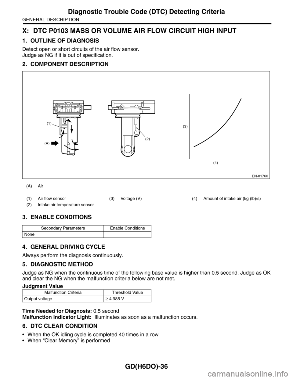
Detect open or short circuits of the air flow sensor.
Judge as NG if it is out of specification.
2. COMPONENT DESCRIPTION
3. ENABLE CONDITIONS
4. GENERAL DRIVING CYCLE
Always perform the diagnosis continuously.
5. DIAGNOSTIC METHOD
Judge as NG when the continuous time of the following base value is higher than 0.5 second. Judge as OK
and clear the NG when the malfunction criteria below are not met.
Time Needed for Diagnosis: 0.5 second
Malfunction Indicator Light: Illuminates as soon as a malfunction occurs.
6. DTC CLEAR CONDITION
•When the OK idling cycle is completed 40 times in a row
•When “Clear Memory” is performed
(A) Air
(1) Air flow sensor (3) Voltage (V) (4) Amount of intake air (kg (lb)/s)
(2) Intake air temperature sensor
Secondary Parameters Enable Conditions
None
Judgment Value
Malfunction Criteria Threshold Value
Output voltage≥ 4.985 V
EN-01766
(3)
(4)
(2)
(1)
(A)
Page 1649 of 2453
GD(H6DO)-37
Diagnostic Trouble Code (DTC) Detecting Criteria
GENERAL DESCRIPTION
7. MALFUNCTION INDICATOR LIGHT CLEAR CONDITIONS
•When the OK driving cycle is completed 3 times in a row
•When “Clear Memory” is performed
8. FAIL SAFE
Purge control: Not allowed to purge
9. ECM OPERATION AT DTC SETTING
Memorize the freeze frame data. (For test mode $02)
Page 1650 of 2453
GD(H6DO)-38
Diagnostic Trouble Code (DTC) Detecting Criteria
GENERAL DESCRIPTION
Y: DTC P0107 MANIFOLD ABSOLUTE PRESSURE/BAROMETRIC PRESSURE
CIRCUIT LOW INPUT
1. OUTLINE OF DIAGNOSIS
Detect the open or short circuit of intake manifold pressure sensor.
Judge as NG if it is out of specification.
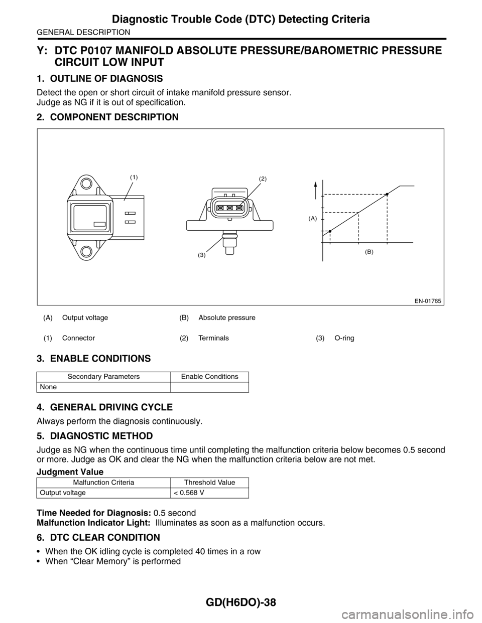
2. COMPONENT DESCRIPTION
3. ENABLE CONDITIONS
4. GENERAL DRIVING CYCLE
Always perform the diagnosis continuously.
5. DIAGNOSTIC METHOD
Judge as NG when the continuous time until completing the malfunction criteria below becomes 0.5 second
or more. Judge as OK and clear the NG when the malfunction criteria below are not met.
Time Needed for Diagnosis: 0.5 second
Malfunction Indicator Light: Illuminates as soon as a malfunction occurs.
6. DTC CLEAR CONDITION
•When the OK idling cycle is completed 40 times in a row
•When “Clear Memory” is performed
(A) Output voltage (B) Absolute pressure
(1) Connector (2) Terminals (3) O-ring
Secondary Parameters Enable Conditions
None
Judgment Value
Malfunction Criteria Threshold Value
Output voltage < 0.568 V
EN-01765
(B)
(A)
(2)
(3)
(1)