SUBARU TRIBECA 2009 1.G Service Workshop Manual
Manufacturer: SUBARU, Model Year: 2009, Model line: TRIBECA, Model: SUBARU TRIBECA 2009 1.GPages: 2453, PDF Size: 46.32 MB
Page 1611 of 2453
FU(H6DO)-50
Fuel Delivery, Return and Evaporation Lines
FUEL INJECTION (FUEL SYSTEMS)
CAUTION:
•Pull the connector to ensure it is connected
securely.
•Make sure the two retainer pawls are en-
gaged in their mating positions in the connec-
tor.
•Be sure to inspect the hoses and their con-
nections for fuel leakage.
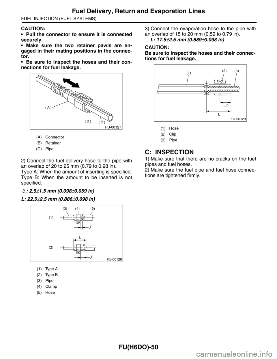
2) Connect the fuel delivery hose to the pipe with
an overlap of 20 to 25 mm (0.79 to 0.98 in).
Type A: When the amount of inserting is specified.
Type B: When the amount to be inserted is not
specified.
2: 2.5±1.5 mm (0.098±0.059 in)
L: 22.5±2.5 mm (0.886±0.098 in)
3) Connect the evaporation hose to the pipe with
an overlap of 15 to 20 mm (0.59 to 0.79 in).
L: 17.5±2.5 mm (0.689±0.098 in)
CAUTION:
Be sure to inspect the hoses and their connec-
tions for fuel leakage.
C: INSPECTION
1) Make sure that there are no cracks on the fuel
pipes and fuel hoses.
2) Make sure the fuel pipe and fuel hose connec-
tions are tightened firmly.
(A) Connector
(B) Retainer
(C) Pipe
(1) Type A
(2) Type B
(3) Pipe
(4) Clamp
(5) Hose
FU-00127
( A )
( B )( C )
(3)(4)(5)
L
(1)
(2)
FU-00128
(1) Hose
(2) Clip
(3) Pipe
FU-00129
(1)(2)
L/2
L
(3)
Page 1612 of 2453
FU(H6DO)-51
Fuel System Trouble in General
FUEL INJECTION (FUEL SYSTEMS)
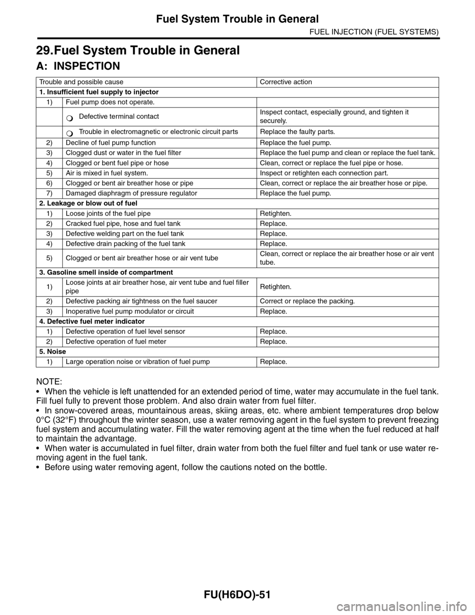
29.Fuel System Trouble in General
A: INSPECTION
NOTE:
•When the vehicle is left unattended for an extended period of time, water may accumulate in the fuel tank.
Fill fuel fully to prevent those problem. And also drain water from fuel filter.
•In snow-covered areas, mountainous areas, skiing areas, etc. where ambient temperatures drop below
0°C (32°F) throughout the winter season, use a water removing agent in the fuel system to prevent freezing
fuel system and accumulating water. Fill the water removing agent at the time when the fuel reduced at half
to maintain the advantage.
•When water is accumulated in fuel filter, drain water from both the fuel filter and fuel tank or use water re-
moving agent in the fuel tank.
•Before using water removing agent, follow the cautions noted on the bottle.
Tr o u b l e a n d p o s s i b l e c a u s e C o r r e c t i v e a c t i o n
1. Insufficient fuel supply to injector
1) Fuel pump does not operate.
Defective terminal contactInspect contact, especially ground, and tighten it
securely.
Tr o u b l e i n e l e c t r o m a g n e t i c o r e l e c t r o n i c c i r c u i t p a r t s R e p l a c e t h e f a u l t y p a r t s .
2) Decline of fuel pump function Replace the fuel pump.
3) Clogged dust or water in the fuel filter Replace the fuel pump and clean or replace the fuel tank.
4) Clogged or bent fuel pipe or hose Clean, correct or replace the fuel pipe or hose.
5) Air is mixed in fuel system. Inspect or retighten each connection part.
6) Clogged or bent air breather hose or pipe Clean, correct or replace the air breather hose or pipe.
7) Damaged diaphragm of pressure regulator Replace the fuel pump.
2. Leakage or blow out of fuel
1) Loose joints of the fuel pipe Retighten.
2) Cracked fuel pipe, hose and fuel tank Replace.
3) Defective welding part on the fuel tank Replace.
4) Defective drain packing of the fuel tank Replace.
5) Clogged or bent air breather hose or air vent tubeClean, correct or replace the air breather hose or air vent
tube.
3. Gasoline smell inside of compartment
1)Loose joints at air breather hose, air vent tube and fuel filler
pipeRetighten.
2) Defective packing air tightness on the fuel saucer Correct or replace the packing.
3) Inoperative fuel pump modulator or circuit Replace.
4. Defective fuel meter indicator
1) Defective operation of fuel level sensor Replace.
2) Defective operation of fuel meter Replace.
5. Noise
1) Large operation noise or vibration of fuel pump Replace.
�
Page 1613 of 2453
FU(H6DO)-52
Fuel System Trouble in General
FUEL INJECTION (FUEL SYSTEMS)
Page 1614 of 2453
GD(H6DO)-2
List of Diagnostic Trouble Code (DTC)
GENERAL DESCRIPTION
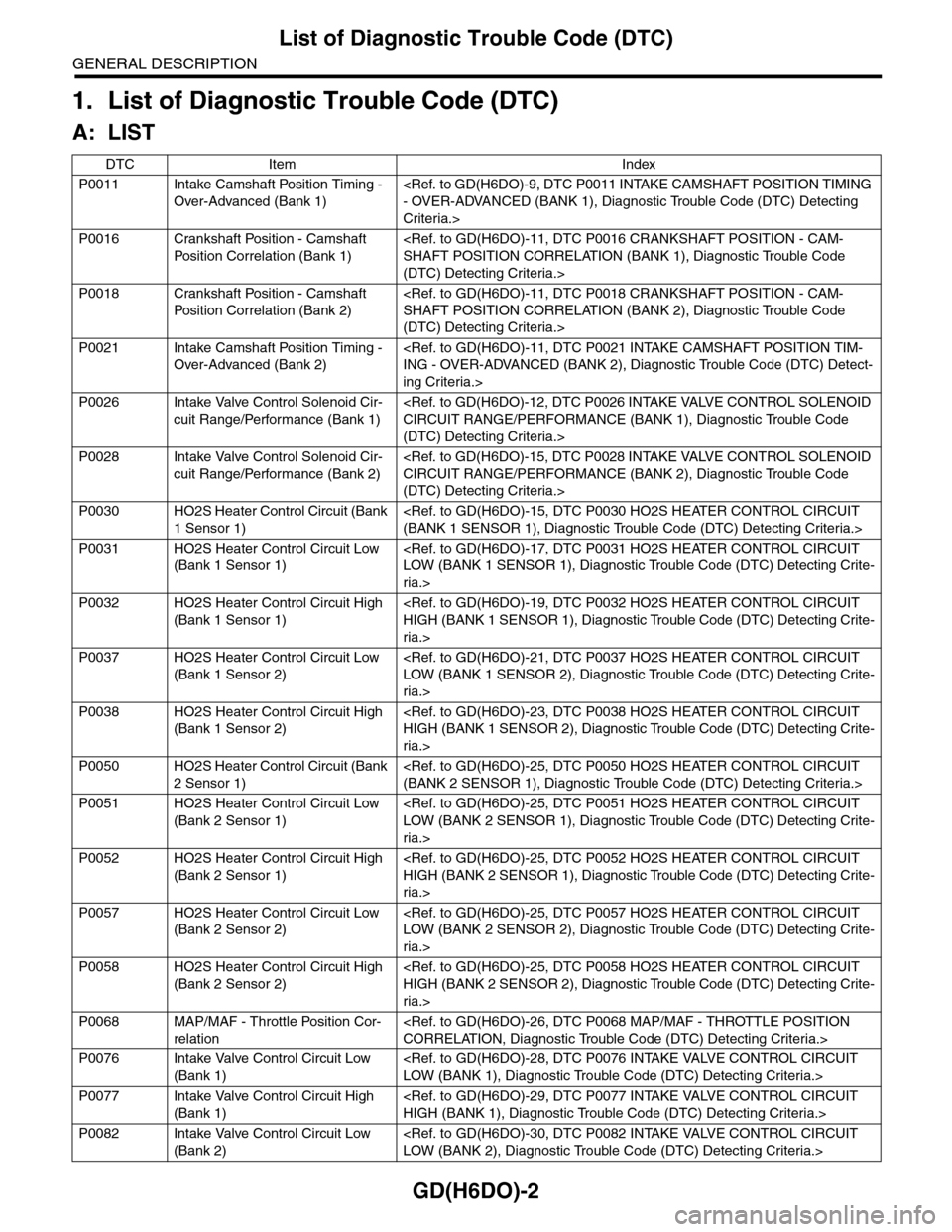
1. List of Diagnostic Trouble Code (DTC)
A: LIST
DTC Item Index
P0011 Intake Camshaft Position Timing -
Over-Advanced (Bank 1)
Criteria.>
P0016 Crankshaft Position - Camshaft
Pos it i o n C o r r el a ti o n ( B a nk 1)
(DTC) Detecting Criteria.>
P0018 Crankshaft Position - Camshaft
Pos it i o n C o r r el a ti o n ( B a nk 2)
(DTC) Detecting Criteria.>
P0021 Intake Camshaft Position Timing -
Over-Advanced (Bank 2)
ing Criteria.>
P0026 Intake Valve Control Solenoid Cir-
cuit Range/Performance (Bank 1)
(DTC) Detecting Criteria.>
P0028 Intake Valve Control Solenoid Cir-
cuit Range/Performance (Bank 2)
(DTC) Detecting Criteria.>
P0030 HO2S Heater Control Circuit (Bank
1 Sensor 1)
P0031 HO2S Heater Control Circuit Low
(Bank 1 Sensor 1)
ria.>
P0032 HO2S Heater Control Circuit High
(Bank 1 Sensor 1)
ria.>
P0037 HO2S Heater Control Circuit Low
(Bank 1 Sensor 2)
ria.>
P0038 HO2S Heater Control Circuit High
(Bank 1 Sensor 2)
ria.>
P0050 HO2S Heater Control Circuit (Bank
2 Sensor 1)
P0051 HO2S Heater Control Circuit Low
(Bank 2 Sensor 1)
ria.>
P0052 HO2S Heater Control Circuit High
(Bank 2 Sensor 1)
ria.>
P0057 HO2S Heater Control Circuit Low
(Bank 2 Sensor 2)
ria.>
P0058 HO2S Heater Control Circuit High
(Bank 2 Sensor 2)
ria.>
P0068 MAP/MAF - Throttle Position Cor-
relation
P0076 Intake Valve Control Circuit Low
(Bank 1)
P0077 Intake Valve Control Circuit High
(Bank 1)
P0082 Intake Valve Control Circuit Low
(Bank 2)
Page 1615 of 2453
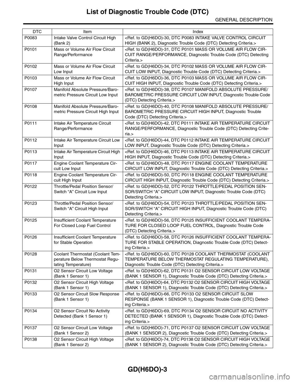
GD(H6DO)-3
List of Diagnostic Trouble Code (DTC)
GENERAL DESCRIPTION
P0083 Intake Valve Control Circuit High
(Bank 2)
P0101 Mass or Volume Air Flow Circuit
Range/Performance
Criteria.>
P0102 Mass or Volume Air Flow Circuit
Low Input
P0103 Mass or Volume Air Flow Circuit
High Input
P0107 Manifold Absolute Pressure/Baro-
metric Pressure Circuit Low Input
(DTC) Detecting Criteria.>
P0108 Manifold Absolute Pressure/Baro-
metric Pressure Circuit High Input
Code (DTC) Detecting Criteria.>
P0111 Intake Air Temperature Circuit
Range/Performance
ria.>
P0112 Intake Air Temperature Circuit Low
Input
P0113 Intake Air Temperature Circuit High
Input
P0117 Engine Coolant Temperature Cir-
cuit Low Input
P0118 Engine Coolant Temperature Cir-
cuit High Input
P0122 Throttle/Pedal Position Sensor/
Switch “A” Circuit Low Input
Detecting Criteria.>
P0123 Throttle/Pedal Position Sensor/
Switch “A” Circuit High Input
Detecting Criteria.>
P0125 Insufficient Coolant Temperature
For Closed Loop Fuel Control
(DTC) Detecting Criteria.>
P0126 Insufficient Coolant Temperature
for Stable Operation
ing Criteria.>
P0128 Coolant Thermostat (Coolant Tem-
perature Below Thermostat Regu-
lating Temperature)
Diagnostic Trouble Code (DTC) Detecting Criteria.>
P0131 O2 Sensor Circuit Low Voltage
(Bank 1 Sensor 1)
P0132 O2 Sensor Circuit High Voltage
(Bank 1 Sensor 1)
P0133 O2 Sensor Circuit Slow Response
(Bank 1 Sensor 1)
ing Criteria.>
P0134 O2 Sensor Circuit No Activity
Detected (Bank 1 Sensor 1)
ing Criteria.>
P0137 O2 Sensor Circuit Low Voltage
(Bank 1 Sensor 2)
P0138 O2 Sensor Circuit High Voltage
(Bank 1 Sensor 2)
DTC Item Index
Page 1616 of 2453

GD(H6DO)-4
List of Diagnostic Trouble Code (DTC)
GENERAL DESCRIPTION
P0139 O2 Sensor Circuit Slow Response
(Bank 1 Sensor 2)
ing Criteria.>
P0140 O2 Sensor Circuit No Activity
Detected (Bank 1 Sensor 2)
ing Criteria.>
P0151 O2 Sensor Circuit Low Voltage
(Bank 2 Sensor 1)
P0152 O2 Sensor Circuit High Voltage
(Bank 2 Sensor 1)
P0153 O2 Sensor Circuit Slow Response
(Bank 2 Sensor 1)
ing Criteria.>
P0154 O2 Sensor Circuit No Activity
Detected (Bank 2 Sensor 1)
ing Criteria.>
P0157 O2 Sensor Circuit Low Voltage
(Bank 2 Sensor 2)
P0158 O2 Sensor Circuit High Voltage
(Bank 2 Sensor 2)
P0159 O2 Sensor Circuit Slow Response
(Bank 2 Sensor 2)
ing Criteria.>
P0160 O2 Sensor Circuit No Activity
Detected (Bank 2 Sensor 2)
ing Criteria.>
P0171 System Too Lean (Bank 1)
P0172 System Too Rich (Bank 1)
P0174 System Too Lean (Bank 2)
P0175 System Too Rich (Bank 2)
P0181 Fuel Temperature Sensor “A” Cir-
cuit Range/Performance
ing Criteria.>
P0182 Fuel Temperature Sensor “A” Cir-
cuit Low Input
P0183 Fuel Temperature Sensor “A” Cir-
cuit High Input
P0196 Engine Oil Temperature Sensor
Circuit Range/Performance
Detecting Criteria.>
P0197 Engine Oil Temperature Sensor
Circuit Low
P0198 Engine Oil Temperature Sensor
Circuit High
P0222 Throttle/Pedal Position Sensor/
Switch “B” Circuit Low Input
Detecting Criteria.>
P0223 Throttle/Pedal Position Sensor/
Switch “B” Circuit High Input
Detecting Criteria.>
P0230 Fuel Pump Primary Circuit
DTC Item Index
Page 1617 of 2453
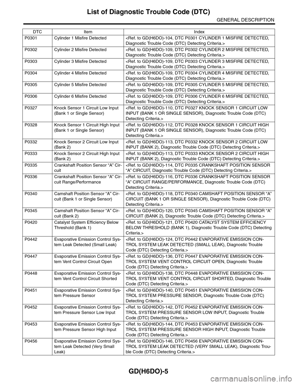
GD(H6DO)-5
List of Diagnostic Trouble Code (DTC)
GENERAL DESCRIPTION
P0301 Cylinder 1 Misfire Detected
P0302 Cylinder 2 Misfire Detected
P0303 Cylinder 3 Misfire Detected
P0304 Cylinder 4 Misfire Detected
P0305 Cylinder 5 Misfire Detected
P0306 Cylinder 6 Misfire Detected
P0327 Knock Sensor 1 Circuit Low Input
(Bank 1 or Single Sensor)
Detecting Criteria.>
P0328 Knock Sensor 1 Circuit High Input
(Bank 1 or Single Sensor)
Detecting Criteria.>
P0332 Knock Sensor 2 Circuit Low Input
(Bank 2)
P0333 Knock Sensor 2 Circuit High Input
(Bank 2)
P0335 Crankshaft Position Sensor “A” Cir-
cuit
P0336 Crankshaft Position Sensor “A” Cir-
cuit Range/Performance
Detecting Criteria.>
P0340 Camshaft Position Sensor “A” Cir-
cuit (Bank 1 or Single Sensor)
Detecting Criteria.>
P0345 Camshaft Position Sensor “A” Cir-
cuit (Bank 2)
P0420 Catalyst System Efficiency Below
Threshold (Bank 1)
Criteria.>
P0442 Evaporative Emission Control Sys-
tem Leak Detected (Small Leak)
Code (DTC) Detecting Criteria.>
P0447 Evaporative Emission Control Sys-
tem Vent Control Circuit Open
Code (DTC) Detecting Criteria.>
P0448 Evaporative Emission Control Sys-
tem Vent Control Circuit Shorted
Code (DTC) Detecting Criteria.>
P0451 Evaporative Emission Control Sys-
tem Pressure Sensor
Detecting Criteria.>
P0452 Evaporative Emission Control Sys-
tem Pressure Sensor Low Input
Code (DTC) Detecting Criteria.>
P0453 Evaporative Emission Control Sys-
tem Pressure Sensor High Input
Code (DTC) Detecting Criteria.>
P0456 Evaporative Emission Control Sys-
tem Leak Detected (Very Small
Leak)
ble Code (DTC) Detecting Criteria.>
DTC Item Index
Page 1618 of 2453
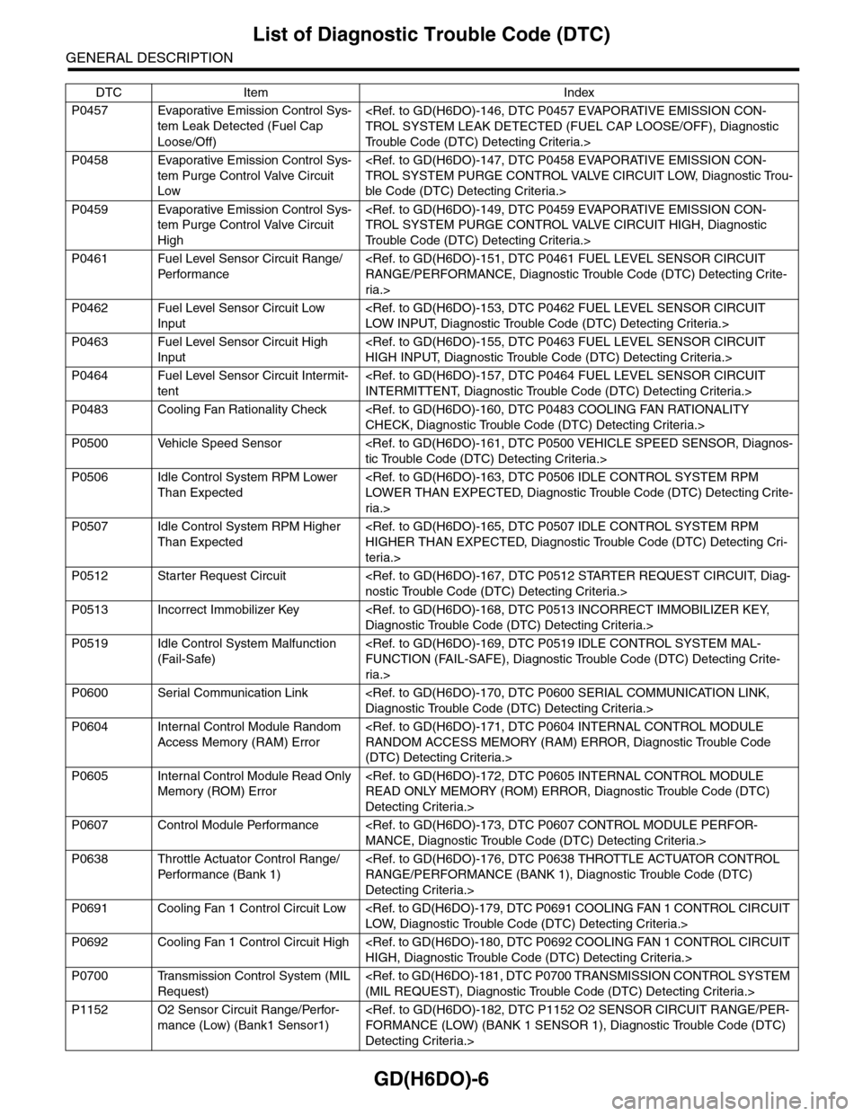
GD(H6DO)-6
List of Diagnostic Trouble Code (DTC)
GENERAL DESCRIPTION
P0457 Evaporative Emission Control Sys-
tem Leak Detected (Fuel Cap
Loose/Off)
Tr o u b l e C o d e ( D T C ) D e t e c t i n g C r i t e r i a . >
P0458 Evaporative Emission Control Sys-
tem Purge Control Valve Circuit
Low
ble Code (DTC) Detecting Criteria.>
P0459 Evaporative Emission Control Sys-
tem Purge Control Valve Circuit
High
Tr o u b l e C o d e ( D T C ) D e t e c t i n g C r i t e r i a . >
P0461 Fuel Level Sensor Circuit Range/
Per fo r m an ce
ria.>
P0462 Fuel Level Sensor Circuit Low
Input
P0463 Fuel Level Sensor Circuit High
Input
P0464 Fuel Level Sensor Circuit Intermit-
tent
P0483 Cooling Fan Rationality Check
P0500 Vehicle Speed Sensor
P0506 Idle Control System RPM Lower
Than Expected
ria.>
P0507 Idle Control System RPM Higher
Than Expected
teria.>
P0512 Starter Request Circuit
P0513 Incorrect Immobilizer Key
P0519 Idle Control System Malfunction
(Fail-Safe)
ria.>
P0600 Serial Communication Link
P0604 Internal Control Module Random
Access Memory (RAM) Error
(DTC) Detecting Criteria.>
P0605 Internal Control Module Read Only
Memory (ROM) Error
Detecting Criteria.>
P0607 Control Module Performance
P0638 Throttle Actuator Control Range/
Per fo r m an ce ( B an k 1 )
Detecting Criteria.>
P0691 Cooling Fan 1 Control Circuit Low
P0692 Cooling Fan 1 Control Circuit High
P0700 Transmission Control System (MIL
Request)
P1152 O2 Sensor Circuit Range/Perfor-
mance (Low) (Bank1 Sensor1)
Detecting Criteria.>
DTC Item Index
Page 1619 of 2453
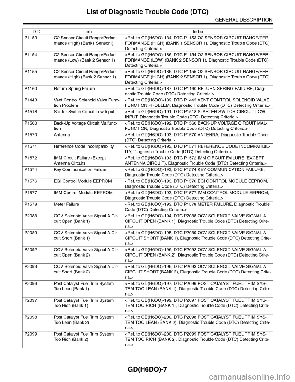
GD(H6DO)-7
List of Diagnostic Trouble Code (DTC)
GENERAL DESCRIPTION
P1153 O2 Sensor Circuit Range/Perfor-
mance (High) (Bank1 Sensor1)
Detecting Criteria.>
P1154 O2 Sensor Circuit Range/Perfor-
mance (Low) (Bank 2 Sensor 1)
Detecting Criteria.>
P1155 O2 Sensor Circuit Range/Perfor-
mance (High) (Bank 2 Sensor 1)
Detecting Criteria.>
P1160 Return Spring Failure
P1443 Vent Control Solenoid Valve Func-
tion Problem
P1518 Starter Switch Circuit Low Input
P1560 Back-Up Voltage Circuit Malfunc-
tion
P1570 Antenna
P1571 Reference Code Incompatibility
P1572 IMM Circuit Failure (Except
Antenna Circuit)
P1574 Key Communication Failure
P1576 EGI Control Module EEPROM
P1577 IMM Control Module EEPROM
P1578 Meter Failure
P2088 OCV Solenoid Valve Signal A Cir-
cuit Open (Bank 1)
ria.>
P2089 OCV Solenoid Valve Signal A Cir-
cuit Short (Bank 1)
ria.>
P2092 OCV Solenoid Valve Signal A Cir-
cuit Open (Bank 2)
ria.>
P2093 OCV Solenoid Valve Signal A Cir-
cuit Short (Bank 2)
ria.>
P2096 Post Catalyst Fuel Trim System
To o L e a n ( B a n k 1 )
ria.>
P2097 Post Catalyst Fuel Trim System
To o R i c h ( B a n k 1 )
ria.>
P2098 Post Catalyst Fuel Trim System
To o L e a n ( B a n k 2 )
ria.>
P2099 Post Catalyst Fuel Trim System
To o R i c h ( B a n k 2 )
ria.>
DTC Item Index
Page 1620 of 2453
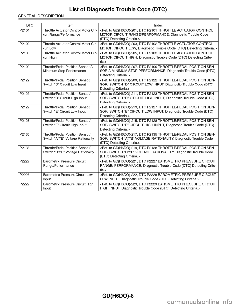
GD(H6DO)-8
List of Diagnostic Trouble Code (DTC)
GENERAL DESCRIPTION
P2101 Throttle Actuator Control Motor Cir-
cuit Range/Performance
(DTC) Detecting Criteria.>
P2102 Throttle Actuator Control Motor Cir-
cuit Low
P2103 Throttle Actuator Control Motor Cir-
cuit High
ria.>
P2109 Throttle/Pedal Position Sensor A
Minimum Stop Performance
Detecting Criteria.>
P2122 Throttle/Pedal Position Sensor/
Switch “D” Circuit Low Input
Detecting Criteria.>
P2123 Throttle/Pedal Position Sensor/
Switch “D” Circuit High Input
Detecting Criteria.>
P2127 Throttle/Pedal Position Sensor/
Switch “E” Circuit Low Input
Detecting Criteria.>
P2128 Throttle/Pedal Position Sensor/
Switch “E” Circuit High Input
Detecting Criteria.>
P2135 Throttle/Pedal Position Sensor/
Switch “A”/“B” Voltage Rationality
(DTC) Detecting Criteria.>
P2138 Throttle/Pedal Position Sensor/
Switch “D”/“E” Voltage Rationality
(DTC) Detecting Criteria.>
P2227 Barometric Pressure Circuit
Range/Performance
ria.>
P2228 Barometric Pressure Circuit Low
Input
P2229 Barometric Pressure Circuit High
Input
DTC Item Index