fuse SUBARU TRIBECA 2009 1.G Service User Guide
[x] Cancel search | Manufacturer: SUBARU, Model Year: 2009, Model line: TRIBECA, Model: SUBARU TRIBECA 2009 1.GPages: 2453, PDF Size: 46.32 MB
Page 175 of 2453
CC(ETC)(diag)-8
Subaru Select Monitor
CRUISE CONTROL SYSTEM (DIAGNOSTICS)
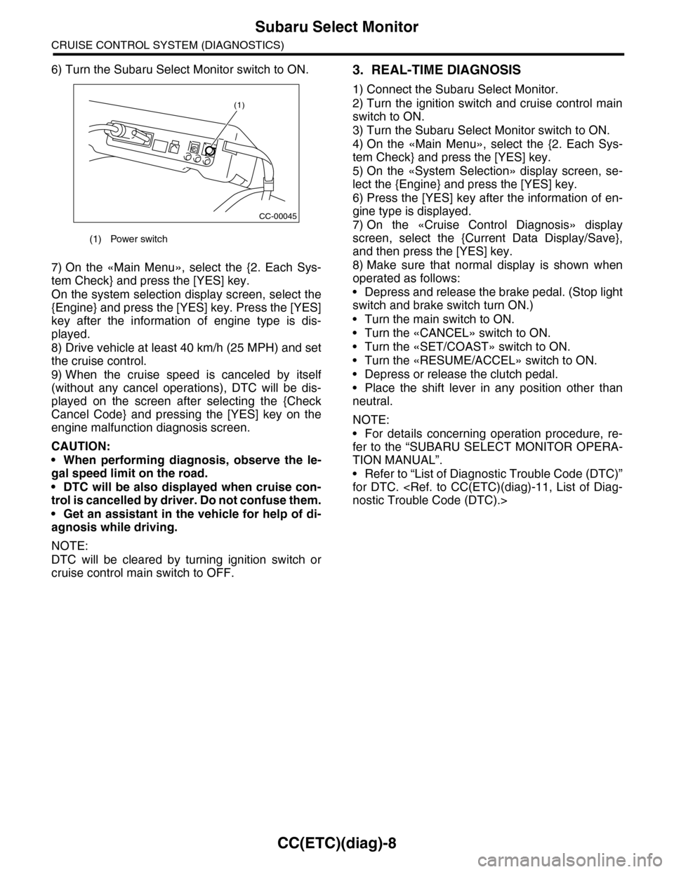
6) Turn the Subaru Select Monitor switch to ON.
7) On the «Main Menu», select the {2. Each Sys-
tem Check} and press the [YES] key.
On the system selection display screen, select the
{Engine} and press the [YES] key. Press the [YES]
key after the information of engine type is dis-
played.
8) Drive vehicle at least 40 km/h (25 MPH) and set
the cruise control.
9) When the cruise speed is canceled by itself
(without any cancel operations), DTC will be dis-
played on the screen after selecting the {Check
Cancel Code} and pressing the [YES] key on the
engine malfunction diagnosis screen.
CAUTION:
•When performing diagnosis, observe the le-
gal speed limit on the road.
•DTC will be also displayed when cruise con-
trol is cancelled by driver. Do not confuse them.
•Get an assistant in the vehicle for help of di-
agnosis while driving.
NOTE:
DTC will be cleared by turning ignition switch or
cruise control main switch to OFF.
3. REAL-TIME DIAGNOSIS
1) Connect the Subaru Select Monitor.
2) Turn the ignition switch and cruise control main
switch to ON.
3) Turn the Subaru Select Monitor switch to ON.
4) On the «Main Menu», select the {2. Each Sys-
tem Check} and press the [YES] key.
5) On the «System Selection» display screen, se-
lect the {Engine} and press the [YES] key.
6) Press the [YES] key after the information of en-
gine type is displayed.
7) On the «Cruise Control Diagnosis» display
screen, select the {Current Data Display/Save},
and then press the [YES] key.
8) Make sure that normal display is shown when
operated as follows:
•Depress and release the brake pedal. (Stop light
switch and brake switch turn ON.)
•Turn the main switch to ON.
•Turn the «CANCEL» switch to ON.
•Turn the «SET/COAST» switch to ON.
•Turn the «RESUME/ACCEL» switch to ON.
•Depress or release the clutch pedal.
•Place the shift lever in any position other than
neutral.
NOTE:
•For details concerning operation procedure, re-
fer to the “SUBARU SELECT MONITOR OPERA-
TION MANUAL”.
•Refer to “List of Diagnostic Trouble Code (DTC)”
for DTC.
(1) Power switch
CC-00045
(1)
Page 182 of 2453
CC(ETC)(diag)-15
Diagnostic Procedure with Diagnostic Trouble Code (DTC)
CRUISE CONTROL SYSTEM (DIAGNOSTICS)
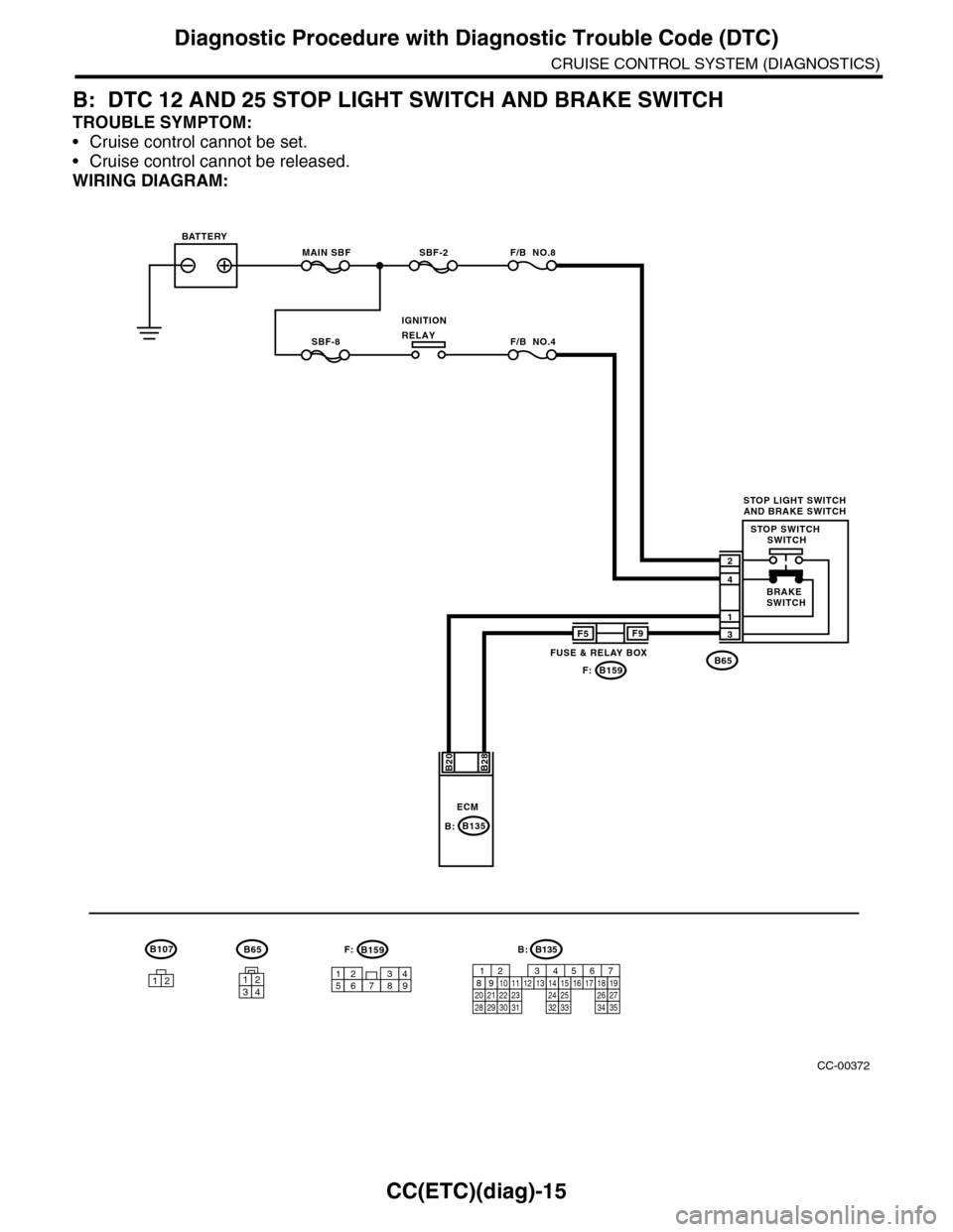
B: DTC 12 AND 25 STOP LIGHT SWITCH AND BRAKE SWITCH
TROUBLE SYMPTOM:
•Cruise control cannot be set.
•Cruise control cannot be released.
WIRING DIAGRAM:
CC-00372
B65
MAIN SBFSBF-2 F/B NO.8
B65
4
3
1
2
B28B20
1234
SBF-8 F/B NO.4
F5
B159
F9
F:
947621538
B159F:
ECM
BATTERY
STOP LIGHT SWITCHAND BRAKE SWITCH
BRAKESWITCH
STOP SWITCH SWITCH
IGNITIONRELAY
FUSE & RELAY BOX
12
B107
B135B:
B135
5672134
29
101112131415252416
30
98171819202821222332312627333435
B:
Page 183 of 2453
CC(ETC)(diag)-16
Diagnostic Procedure with Diagnostic Trouble Code (DTC)
CRUISE CONTROL SYSTEM (DIAGNOSTICS)
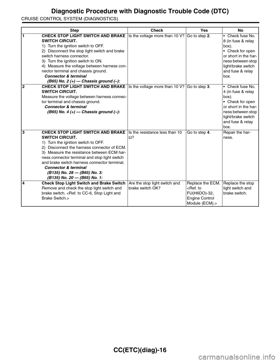
Step Check Yes No
1CHECK STOP LIGHT SWITCH AND BRAKE
SWITCH CIRCUIT.
1) Turn the ignition switch to OFF.
2) Disconnect the stop light switch and brake
switch harness connector.
3) Turn the ignition switch to ON.
4) Measure the voltage between harness con-
nector terminal and chassis ground.
Connector & terminal
(B65) No. 2 (+) — Chassis ground (–):
Is the voltage more than 10 V? Go to step 2.•Check fuse No.
8 (in fuse & relay
box).
•Check for open
or short in the har-
ness between stop
light/brake switch
and fuse & relay
box.
2CHECK STOP LIGHT SWITCH AND BRAKE
SWITCH CIRCUIT.
Measure the voltage between harness connec-
tor terminal and chassis ground.
Connector & terminal
(B65) No. 4 (+) — Chassis ground (–):
Is the voltage more than 10 V? Go to step 3.•Check fuse No.
4 (in fuse & relay
box).
•Check for open
or short in the har-
ness between stop
light/brake switch
and fuse & relay
box.
3CHECK STOP LIGHT SWITCH AND BRAKE
SWITCH CIRCUIT.
1) Turn the ignition switch to OFF.
2) Disconnect the harness connector of ECM.
3) Measure the resistance between ECM har-
ness connector terminal and stop light switch
and brake switch harness connector terminal.
Connector & terminal
(B135) No. 28 — (B65) No. 3:
(B135) No. 20 — (B65) No. 1:
Is the resistance less than 10
Ω?
Go to step 4.Repair the har-
ness.
4Check Stop Light Switch and Brake Switch
Remove and check the stop light switch and
brake switch.
Are the stop light switch and
brake switch OK?
Replace the ECM.
Engine Control
Module (ECM).>
Replace the stop
light switch and
brake switch.
Page 187 of 2453
CC(ETC)(diag)-20
Diagnostic Procedure with Diagnostic Trouble Code (DTC)
CRUISE CONTROL SYSTEM (DIAGNOSTICS)
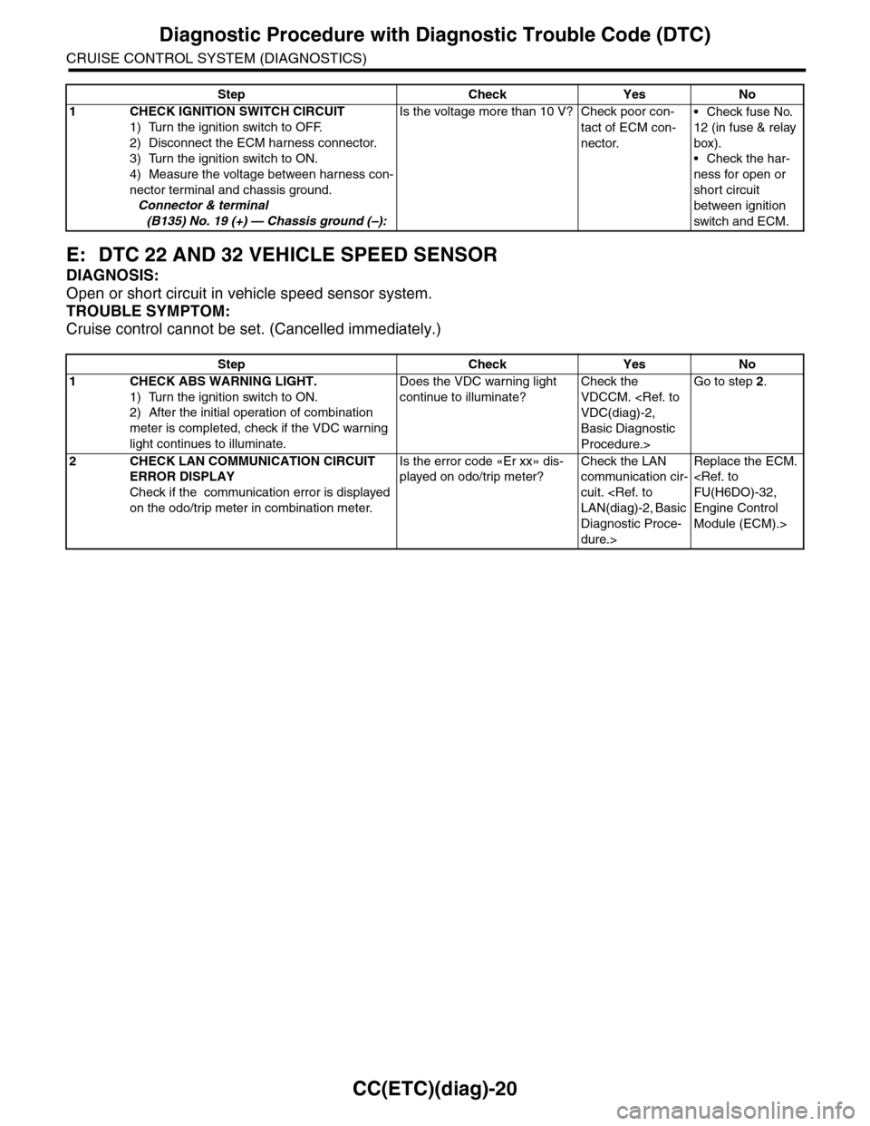
E: DTC 22 AND 32 VEHICLE SPEED SENSOR
DIAGNOSIS:
Open or short circuit in vehicle speed sensor system.
TROUBLE SYMPTOM:
Cruise control cannot be set. (Cancelled immediately.)
Step Check Yes No
1 CHECK IGNITION SWITCH CIRCUIT
1) Turn the ignition switch to OFF.
2) Disconnect the ECM harness connector.
3) Turn the ignition switch to ON.
4) Measure the voltage between harness con-
nector terminal and chassis ground.
Connector & terminal
(B135) No. 19 (+) — Chassis ground (–):
Is the voltage more than 10 V? Check poor con-
tact of ECM con-
nector.
•Check fuse No.
12 (in fuse & relay
box).
•Check the har-
ness for open or
short circuit
between ignition
switch and ECM.
Step Check Yes No
1CHECK ABS WARNING LIGHT.
1) Turn the ignition switch to ON.
2) After the initial operation of combination
meter is completed, check if the VDC warning
light continues to illuminate.
Does the VDC warning light
continue to illuminate?
Check the
VDCCM.
Basic Diagnostic
Procedure.>
Go to step 2.
2CHECK LAN COMMUNICATION CIRCUIT
ERROR DISPLAY
Check if the communication error is displayed
on the odo/trip meter in combination meter.
Is the error code «Er xx» dis-
played on odo/trip meter?
Check the LAN
communication cir-
cuit.
Diagnostic Proce-
dure.>
Replace the ECM.
Engine Control
Module (ECM).>
Page 189 of 2453
ET-3
Audio System
ENTERTAINMENT
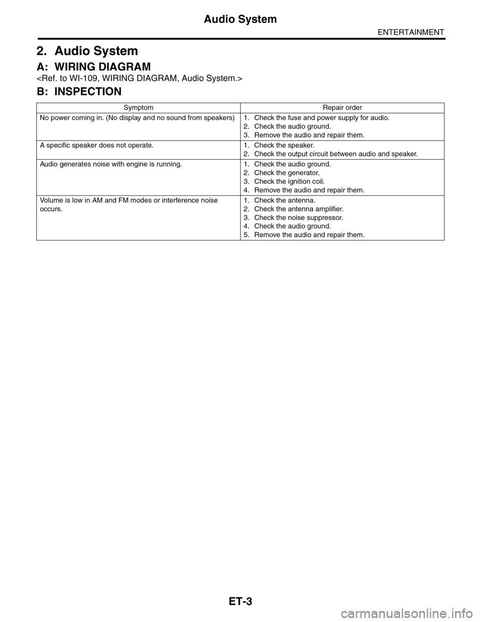
2. Audio System
A: WIRING DIAGRAM
B: INSPECTION
Symptom Repair order
No power coming in. (No display and no sound from speakers) 1. Check the fuse and power supply for audio.
2. Check the audio ground.
3. Remove the audio and repair them.
A specific speaker does not operate. 1. Check the speaker.
2. Check the output circuit between audio and speaker.
Audio generates noise with engine is r unning. 1. C heck the audio ground.
2. Check the generator.
3. Check the ignition coil.
4. Remove the audio and repair them.
Vo l u m e i s l o w i n A M a n d F M m o d e s o r i n t e r f e r e n c e n o i s e
occurs.
1. Check the antenna.
2. Check the antenna amplifier.
3. Check the noise suppressor.
4. Check the audio ground.
5. Remove the audio and repair them.
Page 194 of 2453
ET-8
Multi Function Display (MFD) System
ENTERTAINMENT
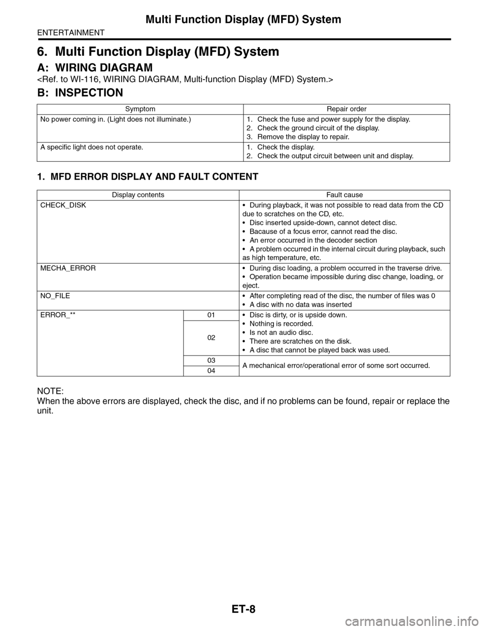
6. Multi Function Display (MFD) System
A: WIRING DIAGRAM
B: INSPECTION
1. MFD ERROR DISPLAY AND FAULT CONTENT
NOTE:
When the above errors are displayed, check the disc, and if no problems can be found, repair or replace the
unit.
Symptom Repair order
No power coming in. (Light does not illuminate.) 1. Check the fuse and power supply for the display.
2. Check the ground circuit of the display.
3. Remove the display to repair.
A specific light does not operate. 1. Check the display.
2. Check the output circuit between unit and display.
Display contents Fault cause
CHECK_DISK • During playback, it was not possible to read data from the CD
due to scratches on the CD, etc.
•Disc inserted upside-down, cannot detect disc.
•Bacause of a focus error, cannot read the disc.
•An error occurred in the decoder section
•A problem occurred in the internal circuit during playback, such
as high temperature, etc.
MECHA_ERROR • During disc loading, a problem occurred in the traverse drive.
•Operation became impossible during disc change, loading, or
eject.
NO_FILE • After completing read of the disc, the number of files was 0
•A disc with no data was inserted
ERROR_** 01 • Disc is dirty, or is upside down.
•Nothing is recorded.
•Is not an audio disc.
•There are scratches on the disk.
•A disc that cannot be played back was used.
02
03A mechanical error/operational error of some sor t occurred.04
Page 301 of 2453
GW-6
Power Window System
GLASS/WINDOWS/MIRRORS
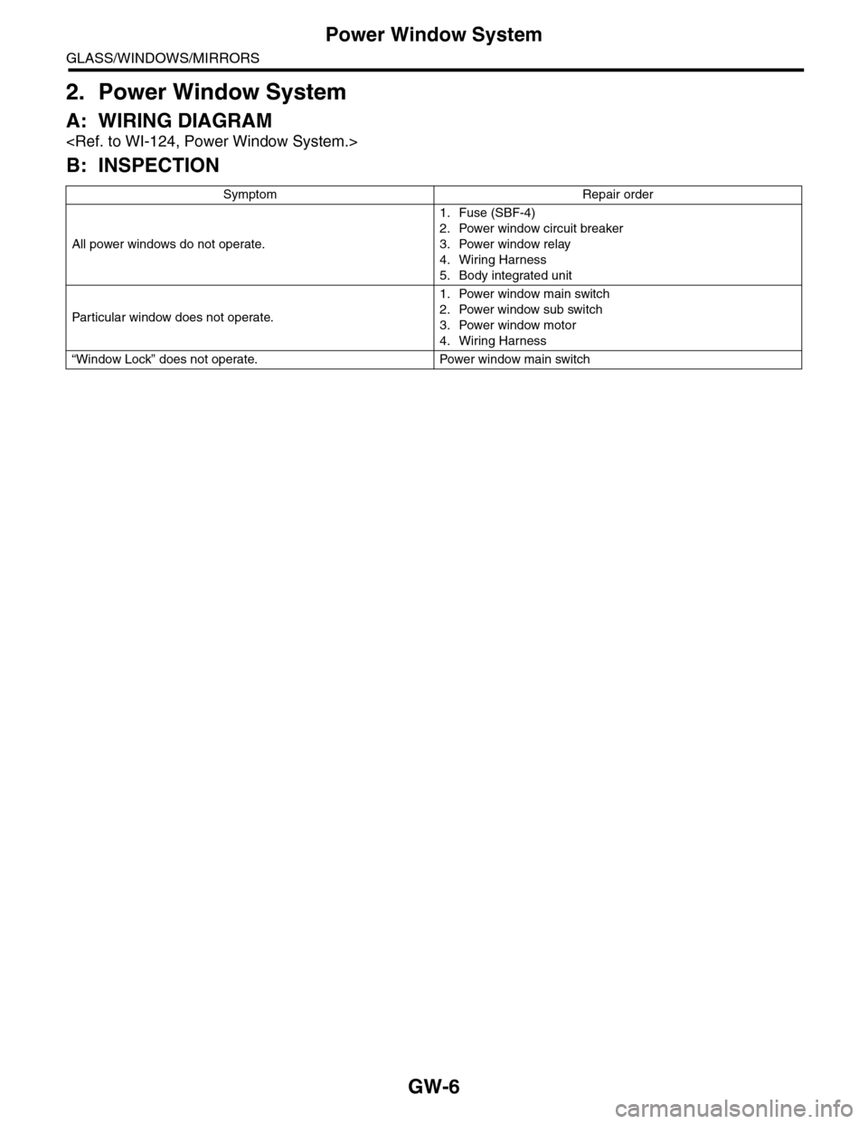
2. Power Window System
A: WIRING DIAGRAM
B: INSPECTION
Symptom Repair order
All power windows do not operate.
1. Fuse (SBF-4)
2. Power window circuit breaker
3. Power window relay
4. Wiring Harness
5. Body integrated unit
Par ticular window does not operate.
1. Power window main switch
2. Power window sub switch
3. Power window motor
4. Wiring Harness
“Window Lock” does not operate. Power window main switch
Page 306 of 2453
GW-11
Remote Control Mirror System
GLASS/WINDOWS/MIRRORS
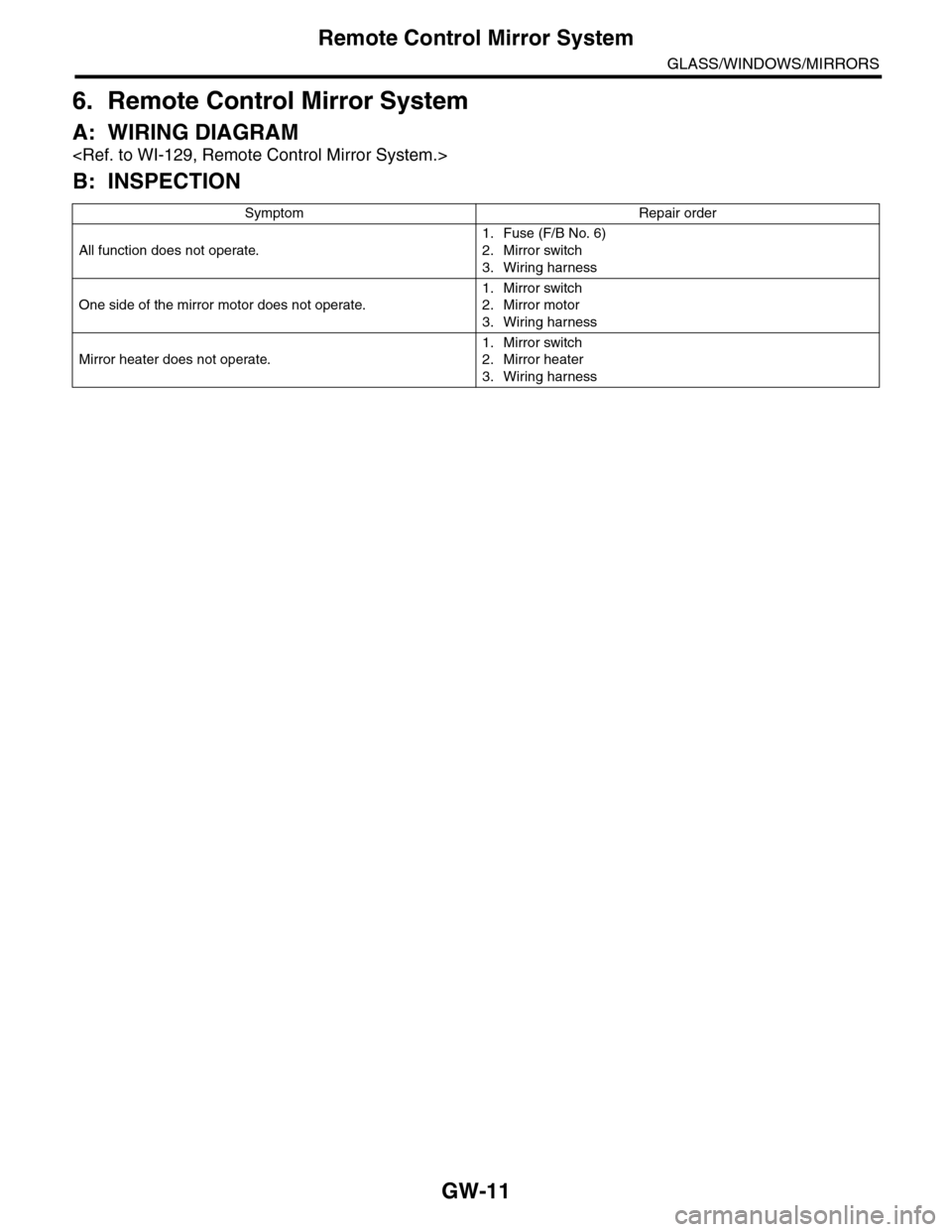
6. Remote Control Mirror System
A: WIRING DIAGRAM
B: INSPECTION
Symptom Repair order
All function does not operate.
1. Fuse (F/B No. 6)
2. Mirror switch
3. Wiring harness
One side of the mirror motor does not operate.
1. Mirror switch
2. Mirror motor
3. Wiring harness
Mirror heater does not operate.
1. Mirror switch
2. Mirror heater
3. Wiring harness
Page 319 of 2453
GW-24
Rear Window Defogger System
GLASS/WINDOWS/MIRRORS
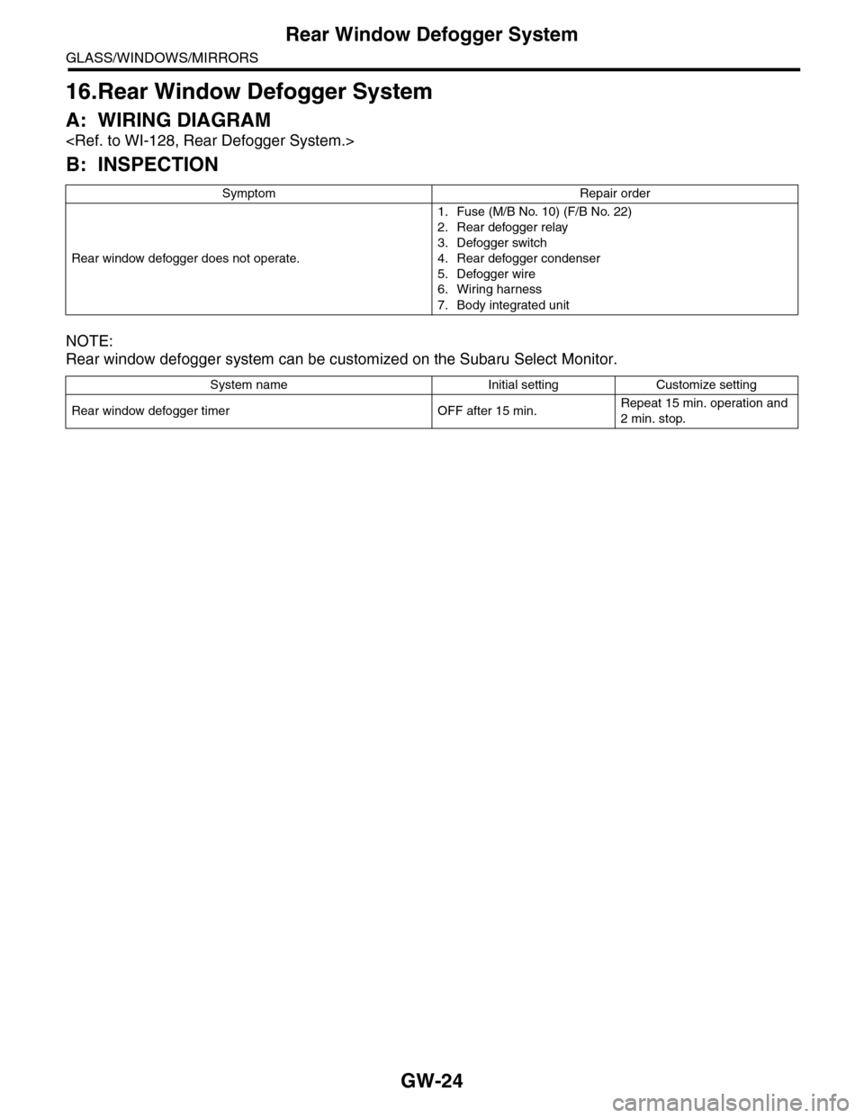
16.Rear Window Defogger System
A: WIRING DIAGRAM
B: INSPECTION
NOTE:
Rear window defogger system can be customized on the Subaru Select Monitor.
Symptom Repair order
Rear window defogger does not operate.
1. Fuse (M/B No. 10) (F/B No. 22)
2. Rear defogger relay
3. Defogger switch
4. Rear defogger condenser
5. Defogger wire
6. Wiring harness
7. Body integrated unit
System name Initial setting Customize setting
Rear window defogger timer OFF after 15 min.Repeat 15 min. operation and
2 min. stop.
Page 325 of 2453
GW-30
Wiper Deicer System
GLASS/WINDOWS/MIRRORS
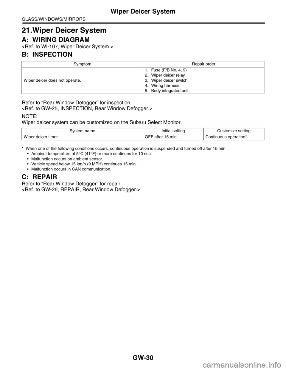
21.Wiper Deicer System
A: WIRING DIAGRAM
B: INSPECTION
Refer to “Rear Window Defogger” for inspection.
NOTE:
Wiper deicer system can be customized on the Subaru Select Monitor.
*: When one of the following conditions occurs, continuous operation is suspended and turned off after 15 min.
•Ambient temperature at 5°C (41°F) or more continues for 10 sec.
•Malfunction occurs on ambient sensor.
•Vehicle speed below 15 km/h (9 MPH) continues 15 min.
•Malfunction occurs in CAN communication.
C: REPAIR
Refer to “Rear Window Defogger” for repair.
Symptom Repair order
Wiper deicer does not operate.
1. Fuse (F/B No. 4, 9)
2. Wiper deicer relay
3. Wiper deicer switch
4. Wiring harness
5. Body integrated unit
System name Initial setting Customize setting
Wiper deicer timer OFF after 15 min. Continuous operation*