fuse SUBARU TRIBECA 2009 1.G Service Service Manual
[x] Cancel search | Manufacturer: SUBARU, Model Year: 2009, Model line: TRIBECA, Model: SUBARU TRIBECA 2009 1.GPages: 2453, PDF Size: 46.32 MB
Page 497 of 2453
LAN(diag)-41
Diagnostic Procedure with Diagnostic Trouble Code (DTC)
LAN SYSTEM (DIAGNOSTICS)
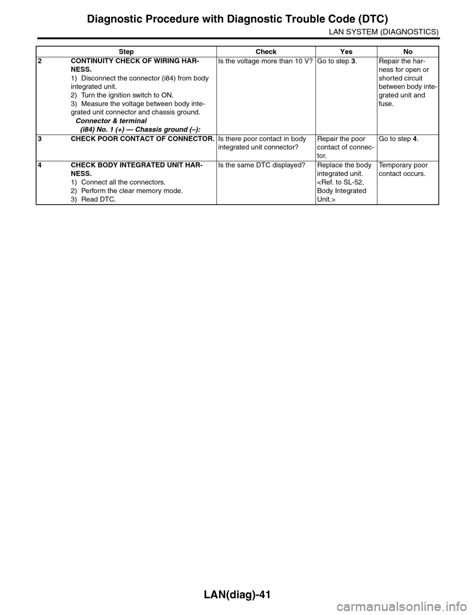
2CONTINUITY CHECK OF WIRING HAR-
NESS.
1) Disconnect the connector (i84) from body
integrated unit.
2) Turn the ignition switch to ON.
3) Measure the voltage between body inte-
grated unit connector and chassis ground.
Connector & terminal
(i84) No. 1 (+) — Chassis ground (–):
Is the voltage more than 10 V? Go to step 3.Repair the har-
ness for open or
shorted circuit
between body inte-
grated unit and
fuse.
3CHECK POOR CONTACT OF CONNECTOR.Is there poor contact in body
integrated unit connector?
Repair the poor
contact of connec-
tor.
Go to step 4.
4CHECK BODY INTEGRATED UNIT HAR-
NESS.
1) Connect all the connectors.
2) Perform the clear memory mode.
3) Read DTC.
Is the same DTC displayed? Replace the body
integrated unit.
Unit.>
Te m p o r a r y p o o r
contact occurs.
Step Check Yes No
Page 498 of 2453
LAN(diag)-42
Diagnostic Procedure with Diagnostic Trouble Code (DTC)
LAN SYSTEM (DIAGNOSTICS)
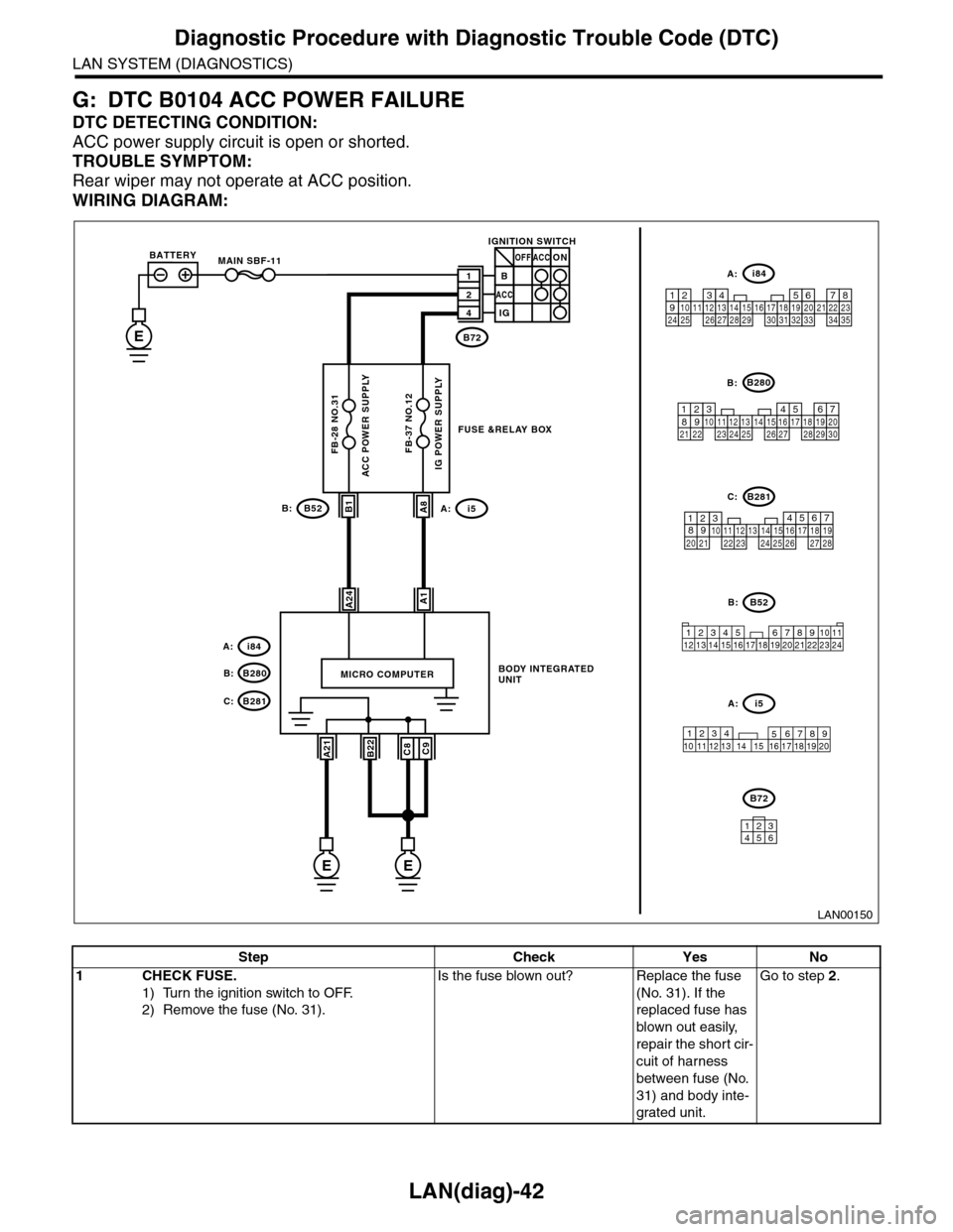
G: DTC B0104 ACC POWER FAILURE
DTC DETECTING CONDITION:
ACC power supply circuit is open or shorted.
TROUBLE SYMPTOM:
Rear wiper may not operate at ACC position.
WIRING DIAGRAM:
LAN00150
BODY INTEGRATED UNIT
A1A24
MICRO COMPUTER
B1A8
B72
IGNITION SWITCH
1B
2
4
ACC
ACCOFF
IG
ON
B52B:
34128910 1112 13 14 15 16 17 18 19 20 21 22 23 24567
B280B:
B281C:
567821943102422 2325111213141526 27281617181920 21
5467821931022 23111213141524 25 26 2716171828 29192021 30
i84A:
1234567891011121314151617181920212223242526272829303132333435
12345678910 11 12 19 2013 14 15 16 17 18
i5A:
ACC POWER SUPPLY
B52i5A:B:
E
MAIN SBF-11
FB-28 NO.31
BATTERY
IG POWER SUPPLY
i84
B280B:
A:
B281C:
A21C9B22C8
EE
FB-37 NO.12
B72
134562
FUSE &RELAY BOX
Step Check Yes No
1CHECK FUSE.
1) Turn the ignition switch to OFF.
2) Remove the fuse (No. 31).
Is the fuse blown out? Replace the fuse
(No. 31). If the
replaced fuse has
blown out easily,
repair the short cir-
cuit of harness
between fuse (No.
31) and body inte-
grated unit.
Go to step 2.
Page 499 of 2453
LAN(diag)-43
Diagnostic Procedure with Diagnostic Trouble Code (DTC)
LAN SYSTEM (DIAGNOSTICS)
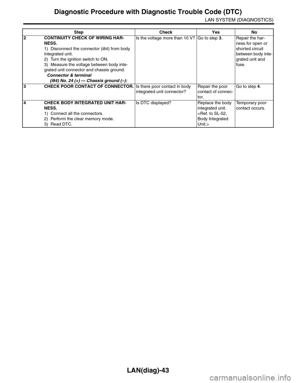
2CONTINUITY CHECK OF WIRING HAR-
NESS.
1) Disconnect the connector (i84) from body
integrated unit.
2) Turn the ignition switch to ON.
3) Measure the voltage between body inte-
grated unit connector and chassis ground.
Connector & terminal
(i84) No. 24 (+) — Chassis ground (–):
Is the voltage more than 10 V? Go to step 3.Repair the har-
ness for open or
shorted circuit
between body inte-
grated unit and
fuse.
3CHECK POOR CONTACT OF CONNECTOR.Is there poor contact in body
integrated unit connector?
Repair the poor
contact of connec-
tor.
Go to step 4.
4CHECK BODY INTEGRATED UNIT HAR-
NESS.
1) Connect all the connectors.
2) Perform the clear memory mode.
3) Read DTC.
Is DTC displayed? Replace the body
integrated unit.
Unit.>
Te m p o r a r y p o o r
contact occurs.
Step Check Yes No
Page 500 of 2453
LAN(diag)-44
Diagnostic Procedure with Diagnostic Trouble Code (DTC)
LAN SYSTEM (DIAGNOSTICS)
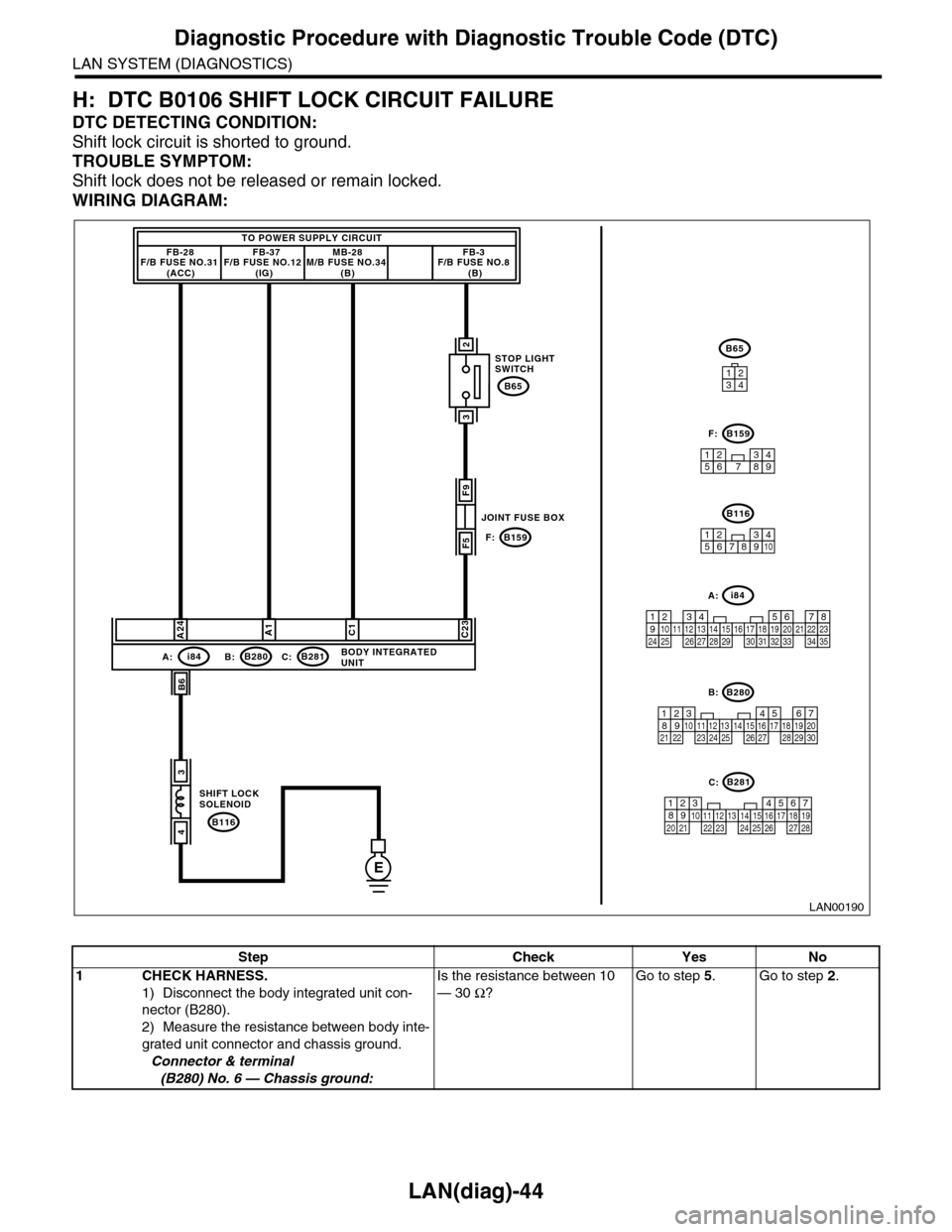
H: DTC B0106 SHIFT LOCK CIRCUIT FAILURE
DTC DETECTING CONDITION:
Shift lock circuit is shorted to ground.
TROUBLE SYMPTOM:
Shift lock does not be released or remain locked.
WIRING DIAGRAM:
B6
TO POWER SUPPLY CIRCUITFB-28F/B FUSE NO.31 (ACC)
FB-37F/B FUSE NO.12 (IG)
MB-28M/B FUSE NO.34 (B)
FB-3F/B FUSE NO.8 (B)
E
F9
F5
3
4
A24C23C1A1
i84A:B280B:B281C:
B159F:
BODY INTEGRATEDUNIT
B116
SHIFT LOCK SOLENOID
JOINT FUSE BOX
STOP LIGHTSWITCH
3
2
B65
LAN00190
12345678910
B116
123495678
B159F:
567821943102422 2325111213141526 27281617181920 21
B281C:
5467821931022 23111213141524 25 26 2716171828 29192021 30
B280B:
3412
1234567891011121314151617181920212223242526272829303132333435
A:i84
B65
Step Check Yes No
1CHECK HARNESS.
1) Disconnect the body integrated unit con-
nector (B280).
2) Measure the resistance between body inte-
grated unit connector and chassis ground.
Connector & terminal
(B280) No. 6 — Chassis ground:
Is the resistance between 10
— 30 Ω?
Go to step 5.Go to step 2.
Page 519 of 2453
LAN(diag)-63
Diagnostic Procedure with Diagnostic Trouble Code (DTC)
LAN SYSTEM (DIAGNOSTICS)
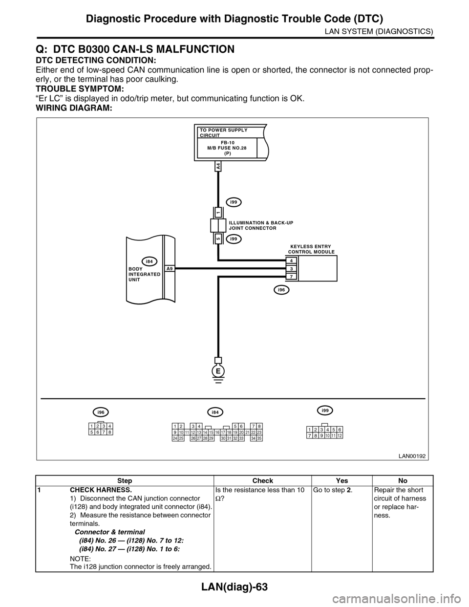
Q: DTC B0300 CAN-LS MALFUNCTION
DTC DETECTING CONDITION:
Either end of low-speed CAN communication line is open or shorted, the connector is not connected prop-
erly, or the terminal has poor caulking.
TROUBLE SYMPTOM:
“Er LC” is displayed in odo/trip meter, but communicating function is OK.
WIRING DIAGRAM:
LAN00192
TO POWER SUPPLY CIRCUITFB-10M/B FUSE NO.28 (P)
1
4
3
7
A9
A4
5
BODY INTEGRATED UNIT
ILLUMINATION & BACK-UPJOINT CONNECTOR
KEYLESS ENTRY CONTROL MODULE
i84
i99
i99
i96
E
i84i96i99
123456789101112131415161718192021222324252627282930313233343510 11 12349561728
12345678
Step Check Yes No
1CHECK HARNESS.
1) Disconnect the CAN junction connector
(i128) and body integrated unit connector (i84).
2) Measure the resistance between connector
terminals.
Connector & terminal
(i84) No. 26 — (i128) No. 7 to 12:
(i84) No. 27 — (i128) No. 1 to 6:
NOTE:The i128 junction connector is freely arranged.
Is the resistance less than 10
Ω?
Go to step 2.Repair the short
circuit of harness
or replace har-
ness.
Page 528 of 2453
LAN(diag)-72
Diagnostic Procedure with Diagnostic Trouble Code (DTC)
LAN SYSTEM (DIAGNOSTICS)
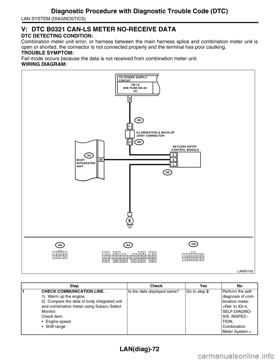
V: DTC B0321 CAN-LS METER NO-RECEIVE DATA
DTC DETECTING CONDITION:
Combination meter unit error, or harness between the main harness splice and combination meter unit is
open or shorted, the connector is not connected properly and the terminal has poor caulking.
TROUBLE SYMPTOM:
Fail mode occurs because the data is not received from combination meter unit.
WIRING DIAGRAM:
LAN00192
TO POWER SUPPLY CIRCUITFB-10M/B FUSE NO.28 (P)
1
4
3
7
A9
A4
5
BODY INTEGRATED UNIT
ILLUMINATION & BACK-UPJOINT CONNECTOR
KEYLESS ENTRY CONTROL MODULE
i84
i99
i99
i96
E
i84i96i99
123456789101112131415161718192021222324252627282930313233343510 11 12349561728
12345678
Step Check Yes No
1CHECK COMMUNICATION LINE.
1) Warm up the engine.
2) Compare the data of body integrated unit
and combination meter using Subaru Select
Monitor.
Check item:
•Engine speed
•Shift range
Is the data displayed same? Go to step 2.Perform the self-
diagnosis of com-
bination meter.
SIS, INSPEC-
TION,
Combination
Meter System.>
Page 593 of 2453
OD(diag)-25
List of Diagnostic Trouble Code (DTC)
OCCUPANT DETECTION SYSTEM (DIAGNOSTICS)
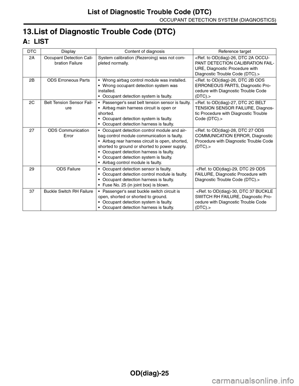
13.List of Diagnostic Trouble Code (DTC)
A: LIST
DTC Display Content of diagnosis Reference target
2A Occupant Detection Cali-
bration Failure
System calibration (Rezeroing) was not com-
pleted normally.
URE, Diagnostic Procedure with
Diagnostic Trouble Code (DTC).>
2B ODS Erroneous Parts • Wrong airbag control module was installed.
•Wrong occupant detection system was
installed.
•Occupant detection system is faulty.
cedure with Diagnostic Trouble Code
(DTC).>
2C Belt Tension Sensor Fail-
ure
•Passenger's seat belt tension sensor is faulty.
•Airbag main harness circuit is open or
shorted.
•Occupant detection system is faulty.
•Occupant detection harness is faulty.
tic Procedure with Diagnostic Trouble
Code (DTC).>
27 ODS Communication
Error
•Occupant detection control module and air-
bag control module communication is faulty.
•Airbag rear harness circuit is open, shorted,
shorted to ground or shorted to power supply.
•Occupant detection harness is faulty.
•Occupant detection system is faulty.
•Airbag control module is faulty.
Procedure with Diagnostic Trouble Code
(DTC).>
29 ODS Failure • Occupant detection sensor is faulty.
•Occupant detection control module is faulty.
•Occupant detection harness is faulty.
•Fuse No. 25 (in joint box) is blown.
Diagnostic Trouble Code (DTC).>
37 Buckle Switch RH Failure • Passenger's seat buckle switch circuit is
open, shorted or shorted to ground.
•Occupant detection system is faulty.
•Occupant detection harness is faulty.
cedure with Diagnostic Trouble Code
(DTC).>
Page 595 of 2453
OD(diag)-27
Diagnostic Procedure with Diagnostic Trouble Code (DTC)
OCCUPANT DETECTION SYSTEM (DIAGNOSTICS)
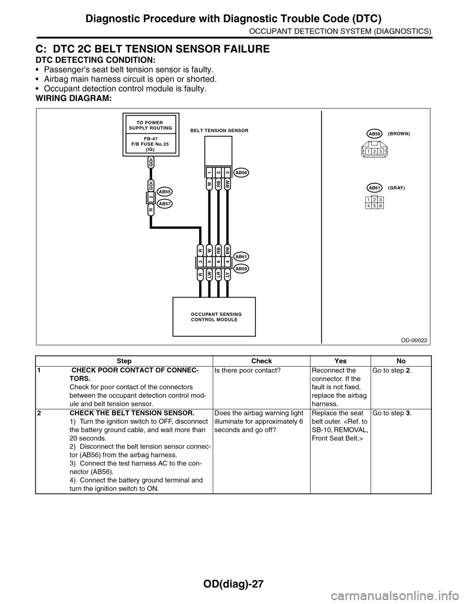
C: DTC 2C BELT TENSION SENSOR FAILURE
DTC DETECTING CONDITION:
•Passenger's seat belt tension sensor is faulty.
•Airbag main harness circuit is open or shorted.
•Occupant detection control module is faulty.
WIRING DIAGRAM:
OD-00022
GOr
FB-47F/B FUSE No.25 (IG)
TO POWER SUPPLY ROUTING
OCCUPANT SENSINGCONTROL MODULE
BELT TENSION SENSOR
3
R
R
5
LW
W
6
LR
RB
4
LY
BW
123
WRBBW
AB61
AB59
AB56
123456
AB61(GRAY)
AB56(BROWN)
123
2
GOr
R
AB55
AB57
Step Check Yes No
1 CHECK POOR CONTACT OF CONNEC-
TORS.
Check for poor contact of the connectors
between the occupant detection control mod-
ule and belt tension sensor.
Is there poor contact? Reconnect the
connector. If the
fault is not fixed,
replace the airbag
harness.
Go to step 2.
2CHECK THE BELT TENSION SENSOR.
1) Turn the ignition switch to OFF, disconnect
the battery ground cable, and wait more than
20 seconds.
2) Disconnect the belt tension sensor connec-
tor (AB56) from the airbag harness.
3) Connect the test harness AC to the con-
nector (AB56).
4) Connect the battery ground terminal and
turn the ignition switch to ON.
Does the airbag warning light
illuminate for approximately 6
seconds and go off?
Replace the seat
belt outer.
Front Seat Belt.>
Go to step 3.
Page 597 of 2453
OD(diag)-29
Diagnostic Procedure with Diagnostic Trouble Code (DTC)
OCCUPANT DETECTION SYSTEM (DIAGNOSTICS)
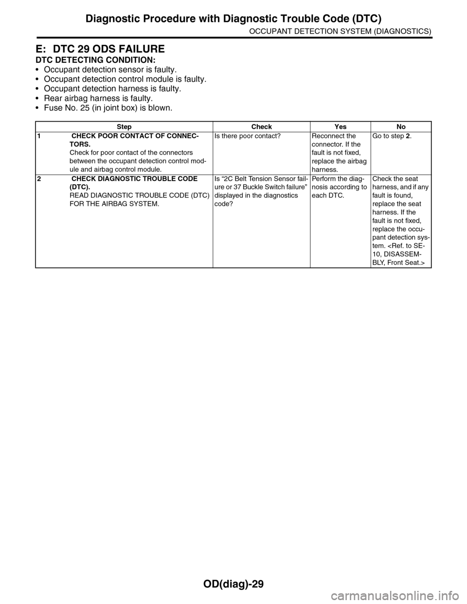
E: DTC 29 ODS FAILURE
DTC DETECTING CONDITION:
•Occupant detection sensor is faulty.
•Occupant detection control module is faulty.
•Occupant detection harness is faulty.
•Rear airbag harness is faulty.
•Fuse No. 25 (in joint box) is blown.
Step Check Yes No
1 CHECK POOR CONTACT OF CONNEC-
TORS.
Check for poor contact of the connectors
between the occupant detection control mod-
ule and airbag control module.
Is there poor contact? Reconnect the
connector. If the
fault is not fixed,
replace the airbag
harness.
Go to step 2.
2 CHECK DIAGNOSTIC TROUBLE CODE
(DTC).
READ DIAGNOSTIC TROUBLE CODE (DTC)
FOR THE AIRBAG SYSTEM.
Is “2C Belt Tension Sensor fail-
ure or 37 Buckle Switch failure”
displayed in the diagnostics
code?
Pe r for m t h e d ia g -
nosis according to
each DTC.
Check the seat
harness, and if any
fault is found,
replace the seat
harness. If the
fault is not fixed,
replace the occu-
pant detection sys-
tem.
BLY, Front Seat.>
Page 637 of 2453
SL-8
Door Lock Control System
SECURITY AND LOCKS
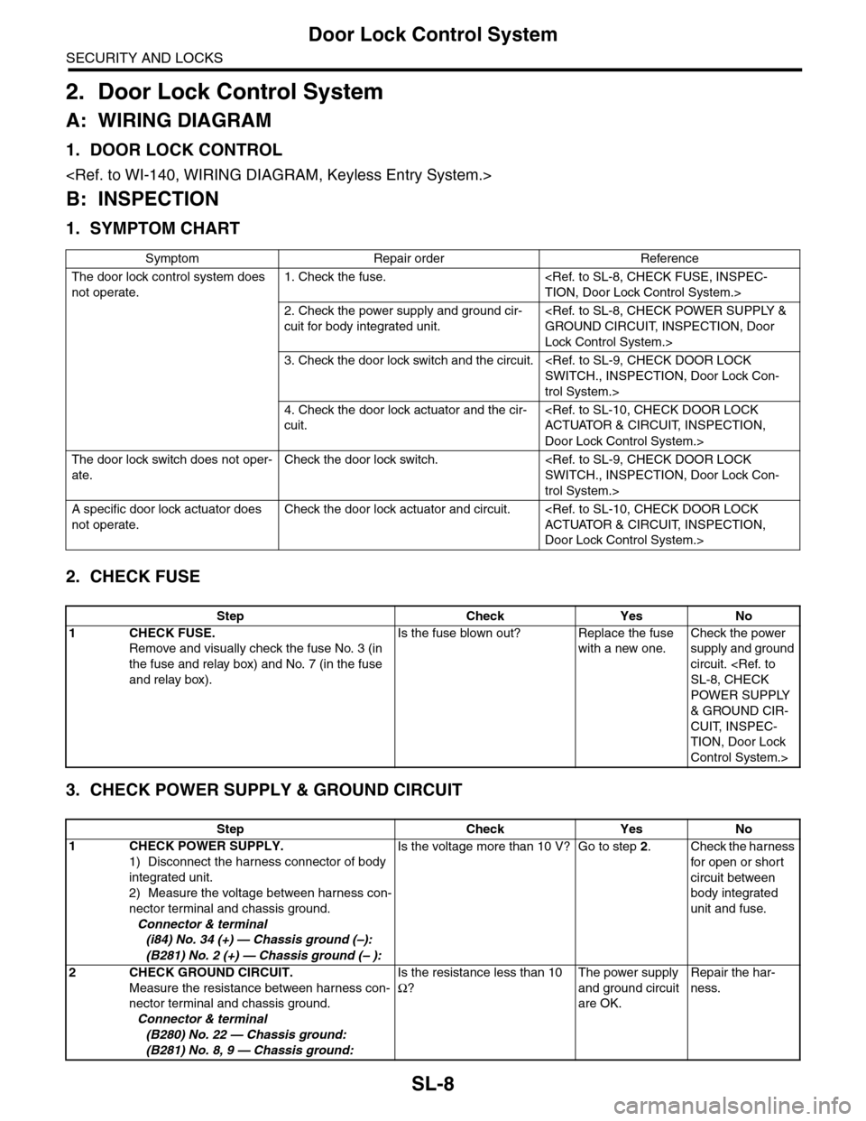
2. Door Lock Control System
A: WIRING DIAGRAM
1. DOOR LOCK CONTROL
B: INSPECTION
1. SYMPTOM CHART
2. CHECK FUSE
3. CHECK POWER SUPPLY & GROUND CIRCUIT
Symptom Repair order Reference
The door lock control system does
not operate.
1. Check the fuse.
2. Check the power supply and ground cir-
cuit for body integrated unit.
Lock Control System.>
3. Check the door lock switch and the circuit.
trol System.>
4. Check the door lock actuator and the cir-
cuit.
Door Lock Control System.>
The door lock switch does not oper-
ate.
Check the door lock switch.
trol System.>
A specific door lock actuator does
not operate.
Check the door lock actuator and circuit.
Door Lock Control System.>
Step Check Yes No
1CHECK FUSE.
Remove and visually check the fuse No. 3 (in
the fuse and relay box) and No. 7 (in the fuse
and relay box).
Is the fuse blown out? Replace the fuse
with a new one.
Check the power
supply and ground
circuit.
POWER SUPPLY
& GROUND CIR-
CUIT, INSPEC-
TION, Door Lock
Control System.>
Step Check Yes No
1CHECK POWER SUPPLY.
1) Disconnect the harness connector of body
integrated unit.
2) Measure the voltage between harness con-
nector terminal and chassis ground.
Connector & terminal
(i84) No. 34 (+) — Chassis ground (–):
(B281) No. 2 (+) — Chassis ground (– ):
Is the voltage more than 10 V? Go to step 2.Check the harness
for open or shor t
circuit between
body integrated
unit and fuse.
2CHECK GROUND CIRCUIT.
Measure the resistance between harness con-
nector terminal and chassis ground.
Connector & terminal
(B280) No. 22 — Chassis ground:
(B281) No. 8, 9 — Chassis ground:
Is the resistance less than 10
Ω?
The power supply
and ground circuit
are OK.
Repair the har-
ness.