headlight SUBARU TRIBECA 2009 1.G Service User Guide
[x] Cancel search | Manufacturer: SUBARU, Model Year: 2009, Model line: TRIBECA, Model: SUBARU TRIBECA 2009 1.GPages: 2453, PDF Size: 46.32 MB
Page 1043 of 2453
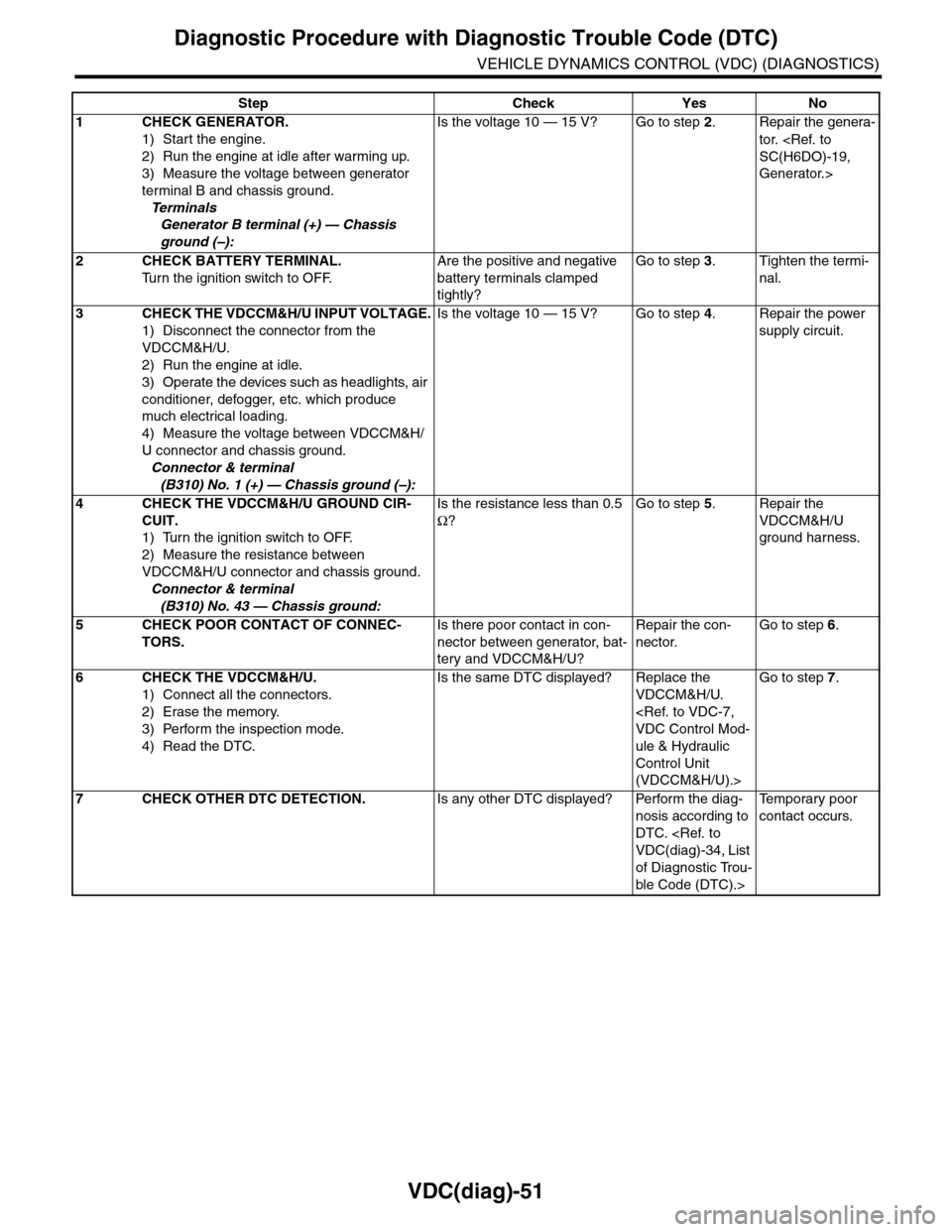
VDC(diag)-51
Diagnostic Procedure with Diagnostic Trouble Code (DTC)
VEHICLE DYNAMICS CONTROL (VDC) (DIAGNOSTICS)
Step Check Yes No
1CHECK GENERATOR.
1) Start the engine.
2) Run the engine at idle after warming up.
3) Measure the voltage between generator
terminal B and chassis ground.
Te r m i n a l s
Generator B terminal (+) — Chassis
ground (–):
Is the voltage 10 — 15 V? Go to step 2.Repair the genera-
tor.
Generator.>
2CHECK BATTERY TERMINAL.
Tu r n t h e i g n i t i o n s w i t c h t o O F F.
Are the positive and negative
battery terminals clamped
tightly?
Go to step 3.Tighten the termi-
nal.
3CHECK THE VDCCM&H/U INPUT VOLTAGE.
1) Disconnect the connector from the
VDCCM&H/U.
2) Run the engine at idle.
3) Operate the devices such as headlights, air
conditioner, defogger, etc. which produce
much electrical loading.
4) Measure the voltage between VDCCM&H/
U connector and chassis ground.
Connector & terminal
(B310) No. 1 (+) — Chassis ground (–):
Is the voltage 10 — 15 V? Go to step 4.Repair the power
supply circuit.
4CHECK THE VDCCM&H/U GROUND CIR-
CUIT.
1) Turn the ignition switch to OFF.
2) Measure the resistance between
VDCCM&H/U connector and chassis ground.
Connector & terminal
(B310) No. 43 — Chassis ground:
Is the resistance less than 0.5
Ω?
Go to step 5.Repair the
VDCCM&H/U
ground harness.
5CHECK POOR CONTACT OF CONNEC-
TORS.
Is there poor contact in con-
nector between generator, bat-
tery and VDCCM&H/U?
Repair the con-
nector.
Go to step 6.
6CHECK THE VDCCM&H/U.
1) Connect all the connectors.
2) Erase the memory.
3) Perform the inspection mode.
4) Read the DTC.
Is the same DTC displayed? Replace the
VDCCM&H/U.
ule & Hydraulic
Control Unit
(VDCCM&H/U).>
Go to step 7.
7CHECK OTHER DTC DETECTION.Is any other DTC displayed? Perform the diag-
nosis according to
DTC.
of Diagnostic Trou-
ble Code (DTC).>
Te m p o r a r y p o o r
contact occurs.
Page 1164 of 2453
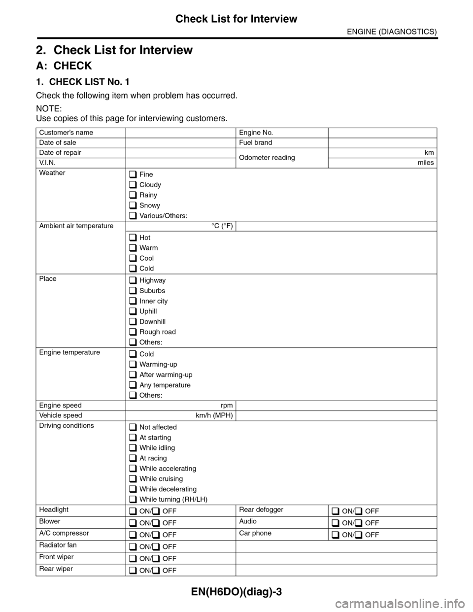
EN(H6DO)(diag)-3
Check List for Interview
ENGINE (DIAGNOSTICS)
2. Check List for Interview
A: CHECK
1. CHECK LIST No. 1
Check the following item when problem has occurred.
NOTE:
Use copies of this page for interviewing customers.
Customer’s name Engine No.
Date of sale Fuel brand
Date of repair Odometer readingkm
V. I . N . miles
Weather Fine
Cloudy
Rainy
Snowy
Various/Others:
Ambient air temperature °C (°F)
Hot
Warm
Cool
Cold
Place Highway
Suburbs
Inner city
Uphill
Downhill
Rough road
Others:
Engine temperature Cold
Warming-up
After warming-up
Any temperature
Others:
Engine speed rpm
Ve h i c l e s p e e d k m / h ( M P H )
Driving conditions Not affected
At starting
While idling
At racing
While accelerating
While cruising
While decelerating
While turning (RH/LH)
Headlight ON/ OFFRear defogger ON/ OFF
Blower ON/ OFFAudio ON/ OFF
A/C compressor ON/ OFFCar phone ON/ OFF
Radiator fan ON/ OFF
Fr o nt wi pe r ON/ OFF
Rear wiper ON/ OFF
Page 2138 of 2453
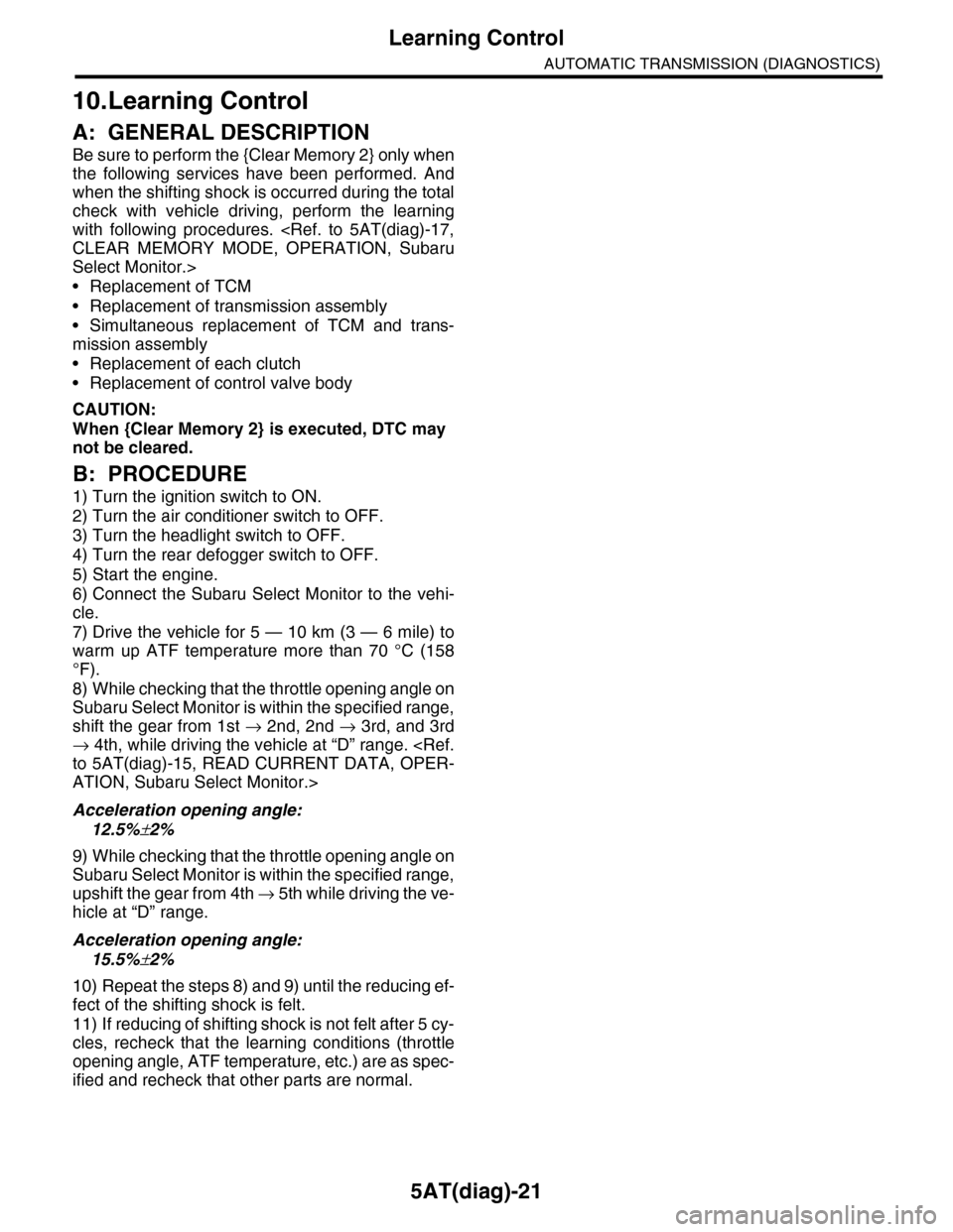
5AT(diag)-21
Learning Control
AUTOMATIC TRANSMISSION (DIAGNOSTICS)
10.Learning Control
A: GENERAL DESCRIPTION
Be sure to perform the {Clear Memory 2} only when
the following services have been performed. And
when the shifting shock is occurred during the total
check with vehicle driving, perform the learning
with following procedures.
Select Monitor.>
•Replacement of TCM
•Replacement of transmission assembly
•Simultaneous replacement of TCM and trans-
mission assembly
•Replacement of each clutch
•Replacement of control valve body
CAUTION:
When {Clear Memory 2} is executed, DTC may
not be cleared.
B: PROCEDURE
1) Turn the ignition switch to ON.
2) Turn the air conditioner switch to OFF.
3) Turn the headlight switch to OFF.
4) Turn the rear defogger switch to OFF.
5) Start the engine.
6) Connect the Subaru Select Monitor to the vehi-
cle.
7) Drive the vehicle for 5 — 10 km (3 — 6 mile) to
warm up ATF temperature more than 70 °C (158
°F).
8) While checking that the throttle opening angle on
Subaru Select Monitor is within the specified range,
shift the gear from 1st → 2nd, 2nd → 3rd, and 3rd
→ 4th, while driving the vehicle at “D” range.
ATION, Subaru Select Monitor.>
Acceleration opening angle:
12.5%±2%
9) While checking that the throttle opening angle on
Subaru Select Monitor is within the specified range,
upshift the gear from 4th → 5 t h w h i l e d r i v i n g t h e v e -
hicle at “D” range.
Acceleration opening angle:
15.5%±2%
10) Repeat the steps 8) and 9) until the reducing ef-
fect of the shifting shock is felt.
11) If reducing of shifting shock is not felt after 5 cy-
cles, recheck that the learning conditions (throttle
opening angle, ATF temperature, etc.) are as spec-
ified and recheck that other parts are normal.
Page 2294 of 2453
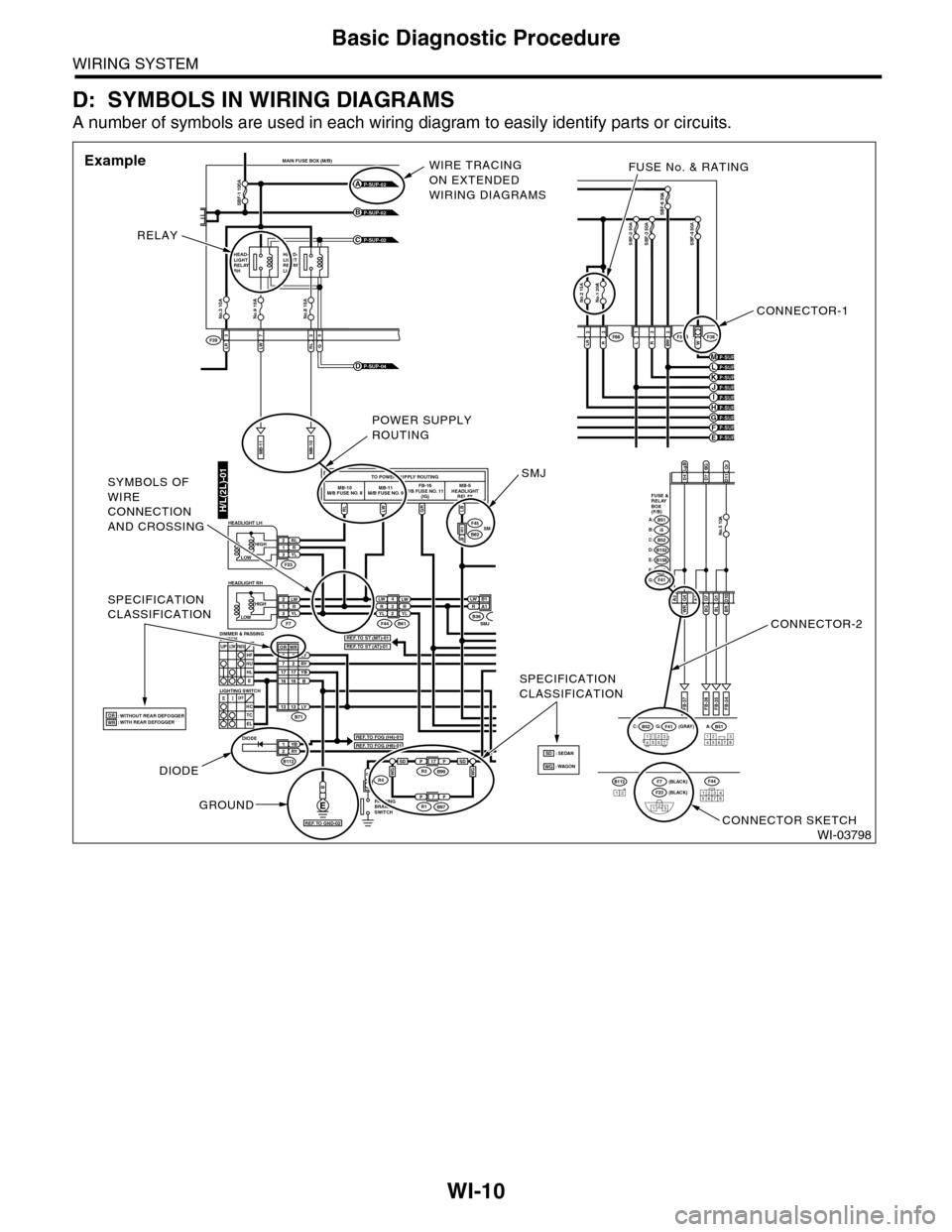
WI-10
Basic Diagnostic Procedure
WIRING SYSTEM
D: SYMBOLS IN WIRING DIAGRAMS
A number of symbols are used in each wiring diagram to easily identify parts or circuits.
WI-03798
LRLWRL3725
MAIN FUSE BOX (M/B)
MB-11MB-10
F39
P-SUP-02B
P-SUP-02A
P-SUP-02C
No.3 10ANo.9 15ANo.8 15A
SBF-1 100A
HEAD-LIGHTRELAYRH
HEAD-LIGHTRELAYLH
G
P-SUP-04D
H/L(2L)-01RLLWGRLB
TO POWER SUPPLY ROUTINGMB-10M/B FUSE NO. 8MB-11M/B FUSE NO. 9FB-16F/B FUSE NO. 11(IG)MB-5HEADLIGHTRELAY
LW 4R3YLLWRYL2
YB1RY2
LW2R1YL3
P
LW B 1RA1
F44
F45
F23
F7B61
B62
B
RL2R1YL3
B71
B112
LY8RY7YBB1716
3
1716
UPLOWPA S SHFHUHLE
SMJLB H1
B36SMJ
DIODE
: WITHOUT REAR DEFOGGER: WITH REAR DEFOGGER
PA R K I N GBRAKESWITCH
R4
OFFHCTCEL
LOWHIGH
HEADLIGHT RH
HEADLIGHT LH
LIGHTING SWITCH
DIMMER & PASSINGSWITCH
LOWHIGH
B51A:B52C:F41G: (GRAY)
(BLACK)(BLACK)
FB-37
D4D7BGD11
A2WR G4BLG1BR D10
FB-35FB-34
123456712345678
LgBOr
FUSE &RELAYBOX(F/B)
i5B:B51A:
B152D:B52C:
B158E:
F41G:F40F:
FB-36
A3BGG7
No.5 10A
P-SUP-03H
P-SUP-03F
P-SUP-04KP-SUP-04J
No.1 20ANo.2 15A
SBF-6 30A
LR2R3L1R3BW 2W
SBF-2 50ASBF-3 50ASBF-4 50A
F36F38F68
P-SUP-04E
P-SUP-04MP-SUP-04L
P-SUP-03I
P-SUP-04G
12345678
F44B11212F23
123
F7
SPECIFICATIONCLASSIFICATION
SPECIFICATIONCLASSIFICATION
2
LY1313
WROR
ORWRREF. TO FOG (H4)-01
REF. TO ST (MT)-01REF. TO ST (AT)-01
REF. TO FOG (H6)-01
REF. TO GND-02
CONNECTOR-1
FUSE No. & RATING
CONNECTOR-2
CONNECTOR SKETCH
RELAY
WIRE TRACINGON EXTENDEDWIRING DIAGRAMS
Example
DIODE
GROUND
POWER SUPPLYROUTING
SMJSYMBOLS OFWIRECONNECTIONAND CROSSING
PP17R3B99
PP7R1B97
WGWGSDSD: WAGON: SEDANSDWG
Page 2297 of 2453
WI-13
Basic Diagnostic Procedure
WIRING SYSTEM
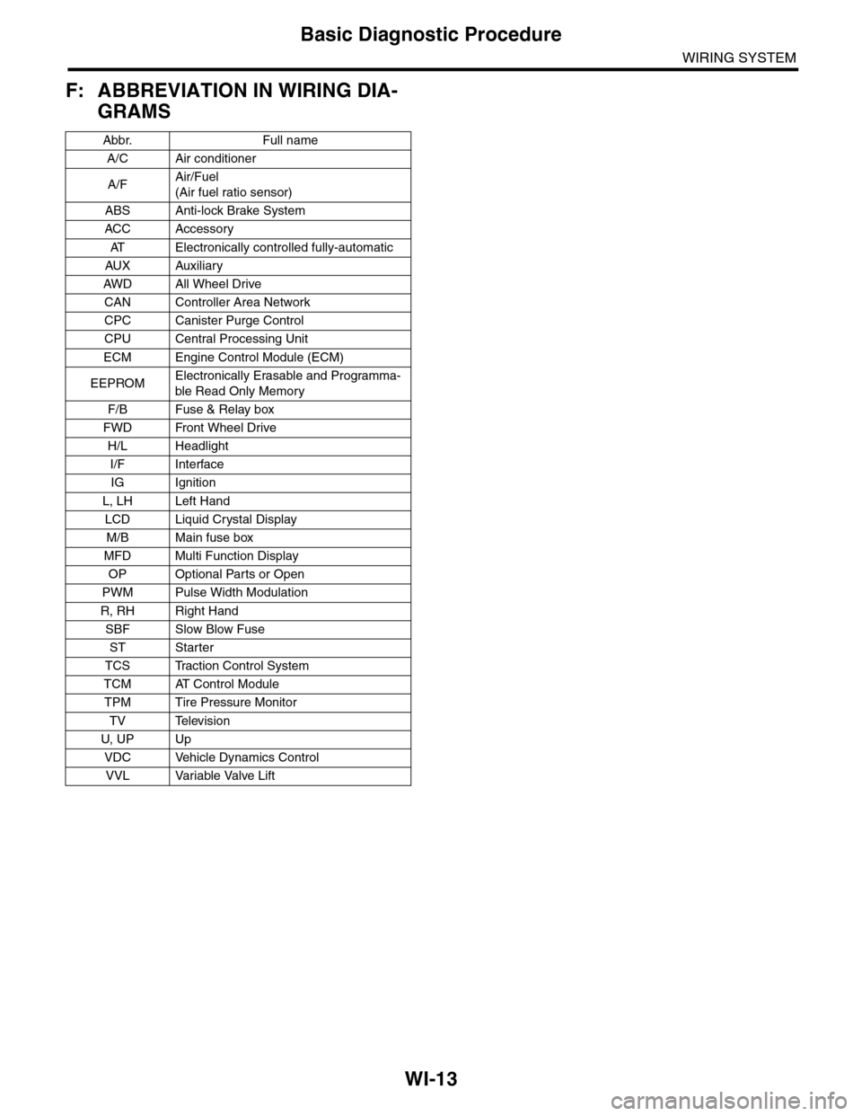
F: ABBREVIATION IN WIRING DIA-
GRAMS
Abbr. Full name
A/C Air conditioner
A/FAir/Fuel
(Air fuel ratio sensor)
ABS Anti-lock Brake System
ACC Accessor y
AT E l e c t r o n i c a l l y c o n t r o l l e d f u l l y - a u t o m a t i c
AUX Auxiliar y
AW D A ll W he e l D r i ve
CAN Controller Area Network
CPC Canister Purge Control
CPU Central Processing Unit
ECM Engine Control Module (ECM)
EEPROMElectronically Erasable and Programma-
ble Read Only Memory
F/B Fuse & Relay box
FWD Front Wheel Drive
H/L Headlight
I/F Interface
IG Ignition
L, LH Left Hand
LCD Liquid Crystal Display
M/B Main fuse box
MFD Multi Function Display
OP Optional Parts or Open
PWM Pulse Width Modulation
R, RH Right Hand
SBF Slow Blow Fuse
ST Starter
TCS Traction Control System
TCM AT Control Module
TPM Tire Pressure Monitor
TV Television
U, UP Up
VDC Vehicle Dynamics Control
VVL Variable Valve Lift
Page 2301 of 2453
WI-17
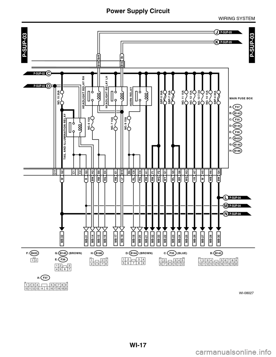
Power Supply Circuit
WIRING SYSTEM
WI-08027
P-SUP-03P-SUP-03
WB
H6
W
H5G4
MAIN FUSE BOX
P-SUP-05K
P-SUP-05J
NO. 14 15ANO. 13 7.5ANO. 12 15ANO. 11 15ANO. 15 20A
NO. 6 15A
SBF-4 30ASBF-7 30ASBF-5 30A
BWWG
H3
BR
G6H7
YRWY
G1G5F2F1
WL
BrBrR
B18B16
B145G:B186H:(BROWN)B144D:(BLUE)F35C:
123456781234567891011121234 567891011 12 13 1415 16 17 18 19 20
B:B143
NO. 7 15ANO. 9 15A
TAIL AND ILLUMINATION RELAY
F37A:
B143B:
F35C:
B144D:
F36E:
B433F:
B145G:
B186H:
RW
H1B6
RL
C8
RG
C9B15
RB
E1C1C2
R
G3H2
RB
B8
RG
E4
W
G2C11
1234567
157628349
P-SUP-02C
P-SUP-02D
MB-21MB-22MB-26MB-25MB-24MB-33MB-27MB-32MB-28MB-19MB-14MB-23MB-32
WGRW
MB-31MB-18MB-17MB-16MB-15MB-20MB-30
P-SUP-04N
P-SUP-04M
P-SUP-04L
HEADLIGHT RELAY RHHEADLIGHT RELAY LHHORN RELAY
LYBW
F36E:
A:F37
1234 5678910 11 12 13 14 15 16 17 18 19 20
(BROWN)B433
12
F:
Page 2304 of 2453
WI-20
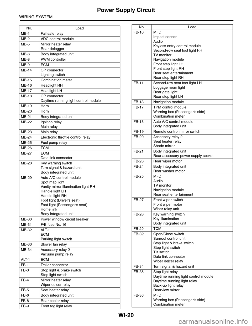
Power Supply Circuit
WIRING SYSTEM
No. Load
MB-1 Fail safe relay
MB-2 VDC control module
MB-5 Mirror heater relay
Rear defogger
MB-6 Body integrated unit
MB-8 PWM controller
MB-9 ECM
MB-14 OP connector
Lighting switch
MB-15 Combination meter
MB-16 Headlight RH
MB-17 Headlight LH
MB-18 OP connector
Daytime running light control module
MB-19 Horn
MB-20 Horn
MB-21 Body integrated unit
MB-22 Ignition relay
Main relay
MB-23 Main relay
MB-24 Electronic throttle control relay
MB-25 Fuel pump relay
MB-26 TCM
MB-27 ECM
Data link connector
MB-28 Key warning switch
Tu r n s i g n a l & h a z a r d u n i t
Body integrated unit
MB-29 Auto A/C control module
Spot map light
Va n i t y m i r r o r i l l u m i n a t i o n l i g h t R H
Handle light LH
Handle light RH
Foot light (Driver’s seat)
Foot light (Passenger’s seat)
Home link
Body integrated unit
MB-30 Power window circuit breaker
MB-31 F/B fuse No. 16
MB-32 ALT-1
ECM
Par king light switch
MB-33 Blower fan relay
MB-34 Accessory relay 2
Va c u u m p u m p r e l ay
ALT-1 ECM
FB-1 Trailer connector
FB-3 Stop light & brake switch
Stop light switch
FB-4 Mirror heater relay
Wiper deicer relay
FB-5 Seat heater relay
FB-6 Body integrated unit
FB-8 Rear cooler relay
FB-9 Front fog light relay
FB-10 MFD
Impact sensor
Audio
Keyless entr y control module
Second-row seat foot light RH
TV monitor
Navigation module
Fr o n t s te p li gh t LH
Fr o n t s te p li gh t RH
Rear seat entertainment
Rear step light RH
FB-11 Second-row seat foot light LH
Luggage room light
Rear gate light
Rear step light LH
FB-13 Navigation module
FB-17 TPM control module
War ning box (Passenger’s side)
Combination meter
FB-18 Auto A/C control module
Body integrated unit
FB-19 Remote control mirror switch
FB-20 Accessory relay 2
Seat heater relay
Shade mirror
FB-21 Body integrated unit
Rear accessory power supply socket
FB-23 Rear wiper motor
FB-24 Body integrated unit
Rear washer motor
FB-25 MFD
Audio
TV monitor
Navigation module
Rear seat entertainment
FB-27 Front wiper switch
Fr o n t wi p er mo t or
Wiper relay unit
FB-28 Key warning switch
Key illumination
Body integrated unit
FB-29 TCM
FB-32 Open/Close switch
Sunroof control unit
Stop light & brake switch
Stop light switch
Tilt switch
Data link connector
Wiper deicer relay
FB-34 Turn signal & hazard unit
FB-35 Stop light relay
Daytime running light control module
Daytime running light relay
Back-up light relay
Rearview mirror
FB-36 MFD
War ning box (Passenger’s side)
Combination meter
No. Load
Page 2370 of 2453
WI-86
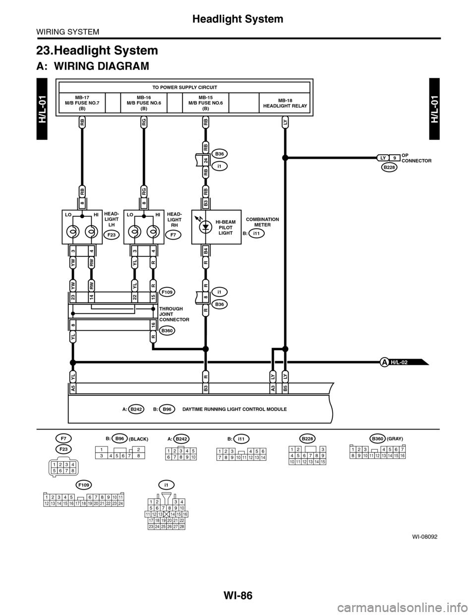
Headlight System
WIRING SYSTEM
23.Headlight System
A: WIRING DIAGRAM
WI-08092
H/L-01H/L-01
MB-17M/B FUSE NO.7(B)
RBRG
RBRG
RB
MB-16M/B FUSE NO.6(B)
MB-15M/B FUSE NO.6(B)
MB-18HEADLIGHT RELAY
TO POWER SUPPLY CIRCUIT
YL
8
R
16
15222314F109
B360
THROUGHJOINTCONNECTOR
RB
24
RB
RB
B3
i1
B36OPCONNECTORB228
LY 9
COMBINATIONMETER
R
B4
i11B:
HILO
YL
3
R
YLR
4
88
HILO
YW
3
RW
YWRW
4
F23
HEAD-LIGHTLH
F7
HEAD-LIGHTRH
(GRAY)B360B228
131415
123456789101112
F109
3412 8910 1112 13 14 15 16 17 18 19 20 21 22 23 24567
i1
56782194310
242223 252726 28
11121314151617181920 21
HI-BEAMPILOTLIGHT
R
8
R
B36
i1
12345678910111213141516
DAYTIME RUNNING LIGHT CONTROL MODULE
YL
A5
R
B3A3B5
LY
B96B:B242A:
LY
H/L-02A
12346789510
B242A:
14723568
B96B:
LY
(BLACK)i11
123 45678910 11 12 13 14
B:F7
F23
34561278
Page 2371 of 2453
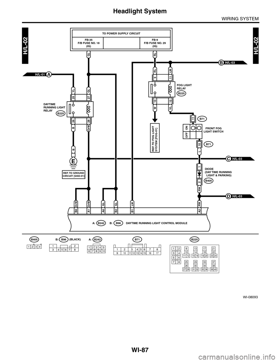
WI-87
Headlight System
WIRING SYSTEM
WI-08093
H/L-02H/L-02
FB-35F/B FUSE NO. 18(IG)
FB-9F/B FUSE NO. 29(IG)
TO POWER SUPPLY CIRCUIT
DAYTIMERUNNING LIGHTRELAYB225
FOG LIGHTRELAY
B225
DIODE (DAY TIME RUNNING LIGHT & PARKING)
FRONT FOGLIGHT SWITCH
B405
B71
B71
DAYTIME RUNNING LIGHT CONTROL MODULE
H/L-03B
H/L-03C
H/L-03D
GLRL
A1
OrW
B8
OrW
B2
GL
B1A2
LWRW
RW
L
A6
GL
B
REF. TO GROUNDCIRCUIT [GND-01]
RL
9
LW
11
1
2
11
10
ON
OFF
10
W
12
VL
REF. TO FOG LIGHTSYSTEM [FOG-01]
B242A:B71B225
1234678951023456718910 11 12 13 14 15 16 17131415 16
17
27
24
2526
20
212223
293031283235
33343738393640
8
91011 12
12
534
761918
H/L-01A
B242A:B96B:
YL
25
GL
27
26
B
28
OrW
14723568
B96B:(BLACK)B405
1234
Page 2372 of 2453
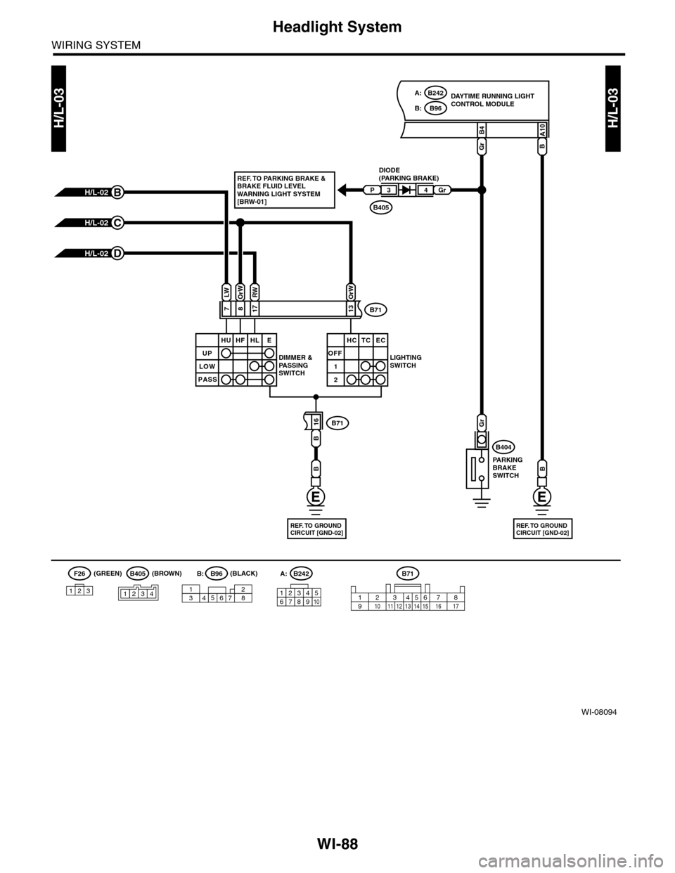
WI-88
Headlight System
WIRING SYSTEM
WI-08094
H/L-03H/L-03
DAYTIME RUNNING LIGHTCONTROL MODULE
DIODE(PARKING BRAKE)
DIMMER &PA S S I N GSWITCH
LIGHTINGSWITCH
PA R K I N GBRAKESWITCH
B405
H/L-02D
H/L-02C
H/L-02B
817
B4
16
Gr
Gr
B71
23456718910 11 12 13 14 15 16 17
A10
B
B404
B71
B71
PGr34
B
B
7
LWOrWRW
13
OrW
REF. TO GROUNDCIRCUIT [GND-02]
B
REF. TO GROUNDCIRCUIT [GND-02]
UP
HU HF HL E
LOW
PASS
OFF
1
2
HC TC EC
B405F26
123
B96B:
B242A:
B242A:
12346789510
14723568
B96B:(BLACK)(BROWN)(GREEN)
REF. TO PARKING BRAKE &BRAKE FLUID LEVELWARNING LIGHT SYSTEM[BRW-01]
1234