hood open SUBARU TRIBECA 2009 1.G Service User Guide
[x] Cancel search | Manufacturer: SUBARU, Model Year: 2009, Model line: TRIBECA, Model: SUBARU TRIBECA 2009 1.GPages: 2453, PDF Size: 46.32 MB
Page 1380 of 2453
EN(H6DO)(diag)-219
Diagnostic Procedure with Diagnostic Trouble Code (DTC)
ENGINE (DIAGNOSTICS)
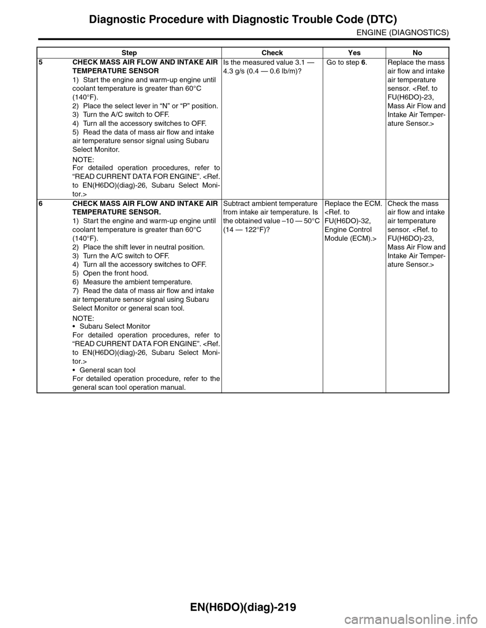
5CHECK MASS AIR FLOW AND INTAKE AIR
TEMPERATURE SENSOR
1) Start the engine and warm-up engine until
coolant temperature is greater than 60°C
(140°F).
2) Place the select lever in “N” or “P” position.
3) Turn the A/C switch to OFF.
4) Turn all the accessory switches to OFF.
5) Read the data of mass air flow and intake
air temperature sensor signal using Subaru
Select Monitor.
NOTE:
For detailed operation procedures, refer to
“READ CURRENT DATA FOR ENGINE”.
tor.>
Is the measured value 3.1 —
4.3 g/s (0.4 — 0.6 lb/m)?
Go to step 6.Replace the mass
air flow and intake
air temperature
sensor.
Mass Air Flow and
Intake Air Temper-
ature Sensor.>
6CHECK MASS AIR FLOW AND INTAKE AIR
TEMPERATURE SENSOR.
1) Start the engine and warm-up engine until
coolant temperature is greater than 60°C
(140°F).
2) Place the shift lever in neutral position.
3) Turn the A/C switch to OFF.
4) Turn all the accessory switches to OFF.
5) Open the front hood.
6) Measure the ambient temperature.
7) Read the data of mass air flow and intake
air temperature sensor signal using Subaru
Select Monitor or general scan tool.
NOTE:•Subaru Select Monitor
For detailed operation procedures, refer to
“READ CURRENT DATA FOR ENGINE”.
tor.>
•General scan tool
For detailed operation procedure, refer to the
general scan tool operation manual.
Subtract ambient temperature
from intake air temperature. Is
the obtained value –10 — 50°C
(14 — 122°F)?
Replace the ECM.
Engine Control
Module (ECM).>
Check the mass
air flow and intake
air temperature
sensor.
Mass Air Flow and
Intake Air Temper-
ature Sensor.>
Step Check Yes No
Page 1494 of 2453
EN(H6DO)(diag)-333
Diagnostic Procedure with Diagnostic Trouble Code (DTC)
ENGINE (DIAGNOSTICS)
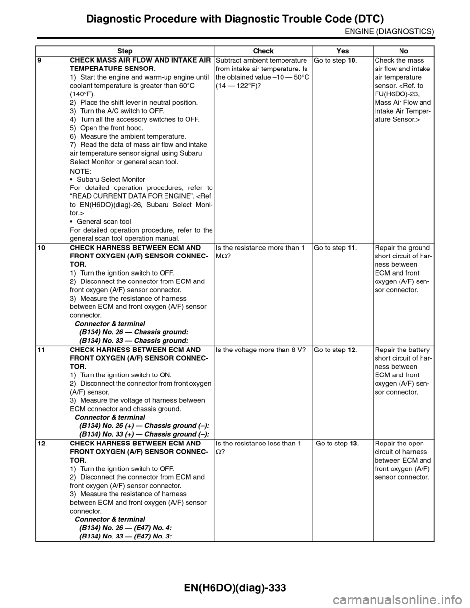
9CHECK MASS AIR FLOW AND INTAKE AIR
TEMPERATURE SENSOR.
1) Start the engine and warm-up engine until
coolant temperature is greater than 60°C
(140°F).
2) Place the shift lever in neutral position.
3) Turn the A/C switch to OFF.
4) Turn all the accessory switches to OFF.
5) Open the front hood.
6) Measure the ambient temperature.
7) Read the data of mass air flow and intake
air temperature sensor signal using Subaru
Select Monitor or general scan tool.
NOTE:•Subaru Select Monitor
For detailed operation procedures, refer to
“READ CURRENT DATA FOR ENGINE”.
tor.>
•General scan tool
For detailed operation procedure, refer to the
general scan tool operation manual.
Subtract ambient temperature
from intake air temperature. Is
the obtained value –10 — 50°C
(14 — 122°F)?
Go to step 10.Check the mass
air flow and intake
air temperature
sensor.
Mass Air Flow and
Intake Air Temper-
ature Sensor.>
10 CHECK HARNESS BETWEEN ECM AND
FRONT OXYGEN (A/F) SENSOR CONNEC-
TOR.
1) Turn the ignition switch to OFF.
2) Disconnect the connector from ECM and
front oxygen (A/F) sensor connector.
3) Measure the resistance of harness
between ECM and front oxygen (A/F) sensor
connector.
Connector & terminal
(B134) No. 26 — Chassis ground:
(B134) No. 33 — Chassis ground:
Is the resistance more than 1
MΩ?
Go to step 11.Repair the ground
short circuit of har-
ness between
ECM and front
oxygen (A/F) sen-
sor connector.
11 CHECK HARNESS BETWEEN ECM AND
FRONT OXYGEN (A/F) SENSOR CONNEC-
TOR.
1) Turn the ignition switch to ON.
2) Disconnect the connector from front oxygen
(A/F) sensor.
3) Measure the voltage of harness between
ECM connector and chassis ground.
Connector & terminal
(B134) No. 26 (+) — Chassis ground (–):
(B134) No. 33 (+) — Chassis ground (–):
Is the voltage more than 8 V? Go to step 12.Repair the battery
short circuit of har-
ness between
ECM and front
oxygen (A/F) sen-
sor connector.
12 CHECK HARNESS BETWEEN ECM AND
FRONT OXYGEN (A/F) SENSOR CONNEC-
TOR.
1) Turn the ignition switch to OFF.
2) Disconnect the connector from ECM and
front oxygen (A/F) sensor connector.
3) Measure the resistance of harness
between ECM and front oxygen (A/F) sensor
connector.
Connector & terminal
(B134) No. 26 — (E47) No. 4:
(B134) No. 33 — (E47) No. 3:
Is the resistance less than 1
Ω?
Go to step 13.Repair the open
circuit of harness
between ECM and
front oxygen (A/F)
sensor connector.
Step Check Yes No
Page 1502 of 2453
EN(H6DO)(diag)-341
Diagnostic Procedure with Diagnostic Trouble Code (DTC)
ENGINE (DIAGNOSTICS)
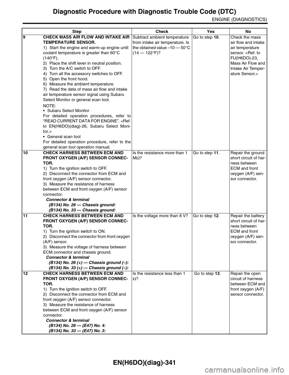
9CHECK MASS AIR FLOW AND INTAKE AIR
TEMPERATURE SENSOR.
1) Start the engine and warm-up engine until
coolant temperature is greater than 60°C
(140°F).
2) Place the shift lever in neutral position.
3) Turn the A/C switch to OFF.
4) Turn all the accessory switches to OFF.
5) Open the front hood.
6) Measure the ambient temperature.
7) Read the data of mass air flow and intake
air temperature sensor signal using Subaru
Select Monitor or general scan tool.
NOTE:•Subaru Select Monitor
For detailed operation procedures, refer to
“READ CURRENT DATA FOR ENGINE”.
tor.>
•General scan tool
For detailed operation procedure, refer to the
general scan tool operation manual.
Subtract ambient temperature
from intake air temperature. Is
the obtained value –10 — 50°C
(14 — 122°F)?
Go to step 10.Check the mass
air flow and intake
air temperature
sensor.
Mass Air Flow and
Intake Air Temper-
ature Sensor.>
10 CHECK HARNESS BETWEEN ECM AND
FRONT OXYGEN (A/F) SENSOR CONNEC-
TOR.
1) Turn the ignition switch to OFF.
2) Disconnect the connector from ECM and
front oxygen (A/F) sensor connector.
3) Measure the resistance of harness
between ECM and front oxygen (A/F) sensor
connector.
Connector & terminal
(B134) No. 26 — Chassis ground:
(B134) No. 33 — Chassis ground:
Is the resistance more than 1
MΩ?
Go to step 11.Repair the ground
short circuit of har-
ness between
ECM and front
oxygen (A/F) sen-
sor connector.
11 CHECK HARNESS BETWEEN ECM AND
FRONT OXYGEN (A/F) SENSOR CONNEC-
TOR.
1) Turn the ignition switch to ON.
2) Disconnect the connector from front oxygen
(A/F) sensor.
3) Measure the voltage of harness between
ECM connector and chassis ground.
Connector & terminal
(B134) No. 26 (+) — Chassis ground (–):
(B134) No. 33 (+) — Chassis ground (–):
Is the voltage more than 8 V? Go to step 12.Repair the battery
short circuit of har-
ness between
ECM and front
oxygen (A/F) sen-
sor connector.
12 CHECK HARNESS BETWEEN ECM AND
FRONT OXYGEN (A/F) SENSOR CONNEC-
TOR.
1) Turn the ignition switch to OFF.
2) Disconnect the connector from ECM and
front oxygen (A/F) sensor connector.
3) Measure the resistance of harness
between ECM and front oxygen (A/F) sensor
connector.
Connector & terminal
(B134) No. 26 — (E47) No. 4:
(B134) No. 33 — (E47) No. 3:
Is the resistance less than 1
Ω?
Go to step 13.Repair the open
circuit of harness
between ECM and
front oxygen (A/F)
sensor connector.
Step Check Yes No
Page 1510 of 2453
EN(H6DO)(diag)-349
Diagnostic Procedure with Diagnostic Trouble Code (DTC)
ENGINE (DIAGNOSTICS)
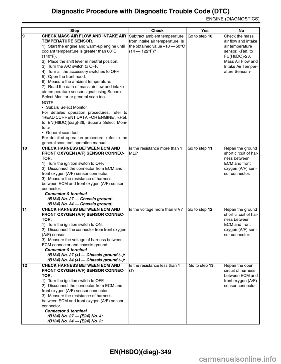
9CHECK MASS AIR FLOW AND INTAKE AIR
TEMPERATURE SENSOR.
1) Start the engine and warm-up engine until
coolant temperature is greater than 60°C
(140°F).
2) Place the shift lever in neutral position.
3) Turn the A/C switch to OFF.
4) Turn all the accessory switches to OFF.
5) Open the front hood.
6) Measure the ambient temperature.
7) Read the data of mass air flow and intake
air temperature sensor signal using Subaru
Select Monitor or general scan tool.
NOTE:•Subaru Select Monitor
For detailed operation procedures, refer to
“READ CURRENT DATA FOR ENGINE”.
tor.>
•General scan tool
For detailed operation procedure, refer to the
general scan tool operation manual.
Subtract ambient temperature
from intake air temperature. Is
the obtained value –10 — 50°C
(14 — 122°F)?
Go to step 10.Check the mass
air flow and intake
air temperature
sensor.
Mass Air Flow and
Intake Air Temper-
ature Sensor.>
10 CHECK HARNESS BETWEEN ECM AND
FRONT OXYGEN (A/F) SENSOR CONNEC-
TOR.
1) Turn the ignition switch to OFF.
2) Disconnect the connector from ECM and
front oxygen (A/F) sensor connector.
3) Measure the resistance of harness
between ECM and front oxygen (A/F) sensor
connector.
Connector & terminal
(B134) No. 27 — Chassis ground:
(B134) No. 34 — Chassis ground:
Is the resistance more than 1
MΩ?
Go to step 11.Repair the ground
short circuit of har-
ness between
ECM and front
oxygen (A/F) sen-
sor connector.
11 CHECK HARNESS BETWEEN ECM AND
FRONT OXYGEN (A/F) SENSOR CONNEC-
TOR.
1) Turn the ignition switch to ON.
2) Disconnect the connector from front oxygen
(A/F) sensor.
3) Measure the voltage of harness between
ECM connector and chassis ground.
Connector & terminal
(B134) No. 27 (+) — Chassis ground (–):
(B134) No. 34 (+) — Chassis ground (–):
Is the voltage more than 8 V? Go to step 12.Repair the ground
short circuit of har-
ness between
ECM and front
oxygen (A/F) sen-
sor connector.
12 CHECK HARNESS BETWEEN ECM AND
FRONT OXYGEN (A/F) SENSOR CONNEC-
TOR.
1) Turn the ignition switch to OFF.
2) Disconnect the connector from ECM and
front oxygen (A/F) sensor connector.
3) Measure the resistance of harness
between ECM and front oxygen (A/F) sensor
connector.
Connector & terminal
(B134) No. 27 — (E24) No. 4:
(B134) No. 34 — (E24) No. 3:
Is the resistance less than 1
Ω?
Go to step 13.Repair the open
circuit of harness
between ECM and
front oxygen (A/F)
sensor connector.
Step Check Yes No
Page 1518 of 2453
EN(H6DO)(diag)-357
Diagnostic Procedure with Diagnostic Trouble Code (DTC)
ENGINE (DIAGNOSTICS)
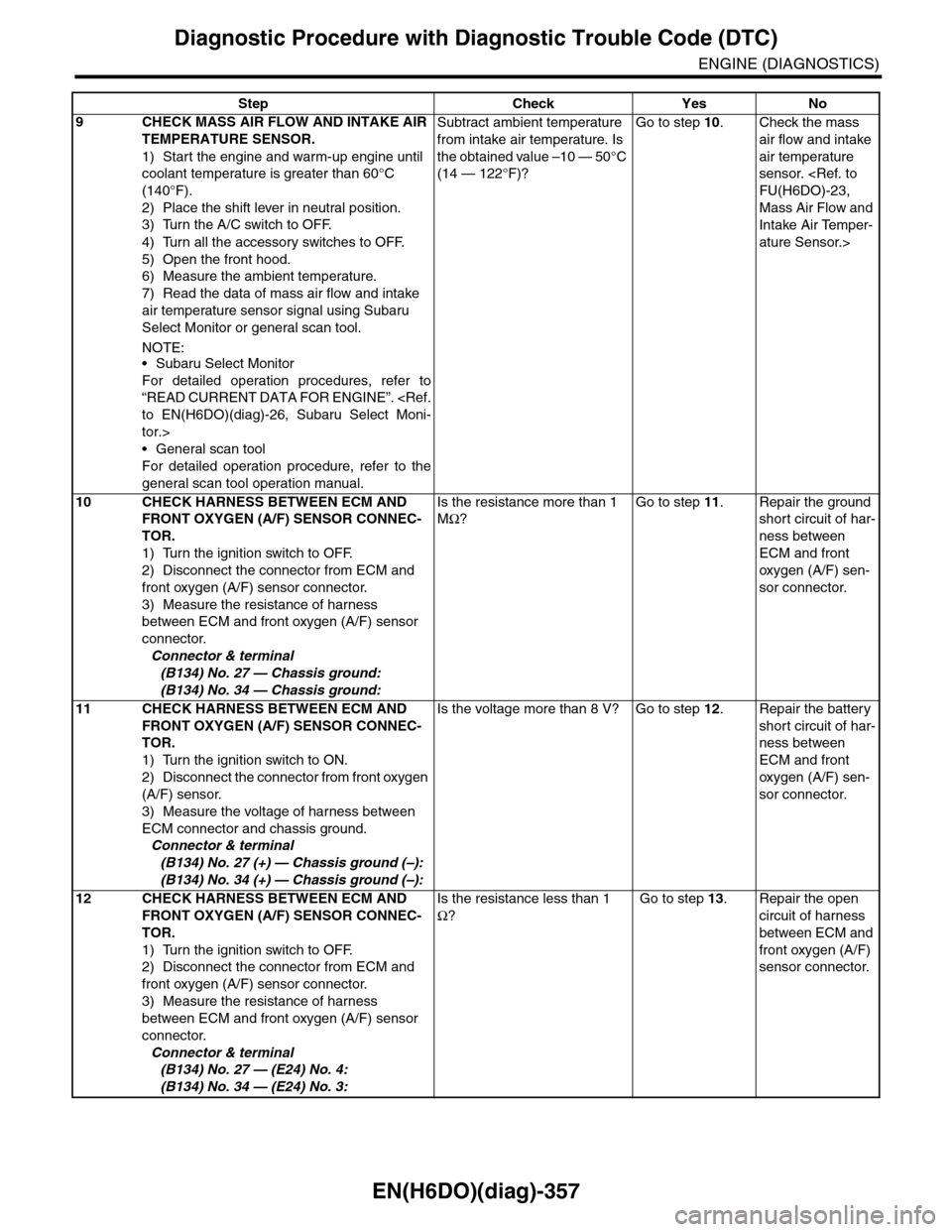
9CHECK MASS AIR FLOW AND INTAKE AIR
TEMPERATURE SENSOR.
1) Start the engine and warm-up engine until
coolant temperature is greater than 60°C
(140°F).
2) Place the shift lever in neutral position.
3) Turn the A/C switch to OFF.
4) Turn all the accessory switches to OFF.
5) Open the front hood.
6) Measure the ambient temperature.
7) Read the data of mass air flow and intake
air temperature sensor signal using Subaru
Select Monitor or general scan tool.
NOTE:•Subaru Select Monitor
For detailed operation procedures, refer to
“READ CURRENT DATA FOR ENGINE”.
tor.>
•General scan tool
For detailed operation procedure, refer to the
general scan tool operation manual.
Subtract ambient temperature
from intake air temperature. Is
the obtained value –10 — 50°C
(14 — 122°F)?
Go to step 10.Check the mass
air flow and intake
air temperature
sensor.
Mass Air Flow and
Intake Air Temper-
ature Sensor.>
10 CHECK HARNESS BETWEEN ECM AND
FRONT OXYGEN (A/F) SENSOR CONNEC-
TOR.
1) Turn the ignition switch to OFF.
2) Disconnect the connector from ECM and
front oxygen (A/F) sensor connector.
3) Measure the resistance of harness
between ECM and front oxygen (A/F) sensor
connector.
Connector & terminal
(B134) No. 27 — Chassis ground:
(B134) No. 34 — Chassis ground:
Is the resistance more than 1
MΩ?
Go to step 11.Repair the ground
short circuit of har-
ness between
ECM and front
oxygen (A/F) sen-
sor connector.
11 CHECK HARNESS BETWEEN ECM AND
FRONT OXYGEN (A/F) SENSOR CONNEC-
TOR.
1) Turn the ignition switch to ON.
2) Disconnect the connector from front oxygen
(A/F) sensor.
3) Measure the voltage of harness between
ECM connector and chassis ground.
Connector & terminal
(B134) No. 27 (+) — Chassis ground (–):
(B134) No. 34 (+) — Chassis ground (–):
Is the voltage more than 8 V? Go to step 12.Repair the battery
short circuit of har-
ness between
ECM and front
oxygen (A/F) sen-
sor connector.
12 CHECK HARNESS BETWEEN ECM AND
FRONT OXYGEN (A/F) SENSOR CONNEC-
TOR.
1) Turn the ignition switch to OFF.
2) Disconnect the connector from ECM and
front oxygen (A/F) sensor connector.
3) Measure the resistance of harness
between ECM and front oxygen (A/F) sensor
connector.
Connector & terminal
(B134) No. 27 — (E24) No. 4:
(B134) No. 34 — (E24) No. 3:
Is the resistance less than 1
Ω?
Go to step 13.Repair the open
circuit of harness
between ECM and
front oxygen (A/F)
sensor connector.
Step Check Yes No
Page 1898 of 2453

ME(H6DO)-32
Engine Assembly
MECHANICAL
10.Engine Assembly
A: REMOVAL
1) Set the vehicle on a lift.
2) Change the bolt mounting position from (A) to
(B), then completely open the front hood.
3) Remove the collector cover.
4) Collect the refrigerant from A/C system.
cedure.>
5) Release the fuel pressure.
6) Remove the battery from vehicle.
7) Remove the air intake duct, air cleaner case and
air intake chamber.
8) Remove the engine front cover.
9) Remove the radiator from the vehicle.
NOTE:
Protect the condenser so that it will not be dam-
aged.
10) Remove the fuel hose bracket.
11) Remove the V-belts.
12) Disconnect the A/C pressure hoses from A/C
compressor.
13) Remove the engine ground terminal.
14) Disconnect the following connector.
(1) Engine harness connectors
(2) Generator connector, terminal and A/C
compressor connector
(3) Power steering switch connector
ME-02652
(A)
(B)
CO-02176
ME-02653
ME-00476
ME-02654
Page 2050 of 2453
5AT-34
Automatic Transmission Assembly
AUTOMATIC TRANSMISSION
9. Automatic Transmission As-
sembly
A: REMOVAL
1) Set the vehicle on a lift.
2) Open the front hood and support with the hood
stay.
3) Disconnect the ground cable from battery.
4) Remove the collector cover.
5) Remove the air intake chamber.
6) Remove the air breather hose.
7) Remove the starter.
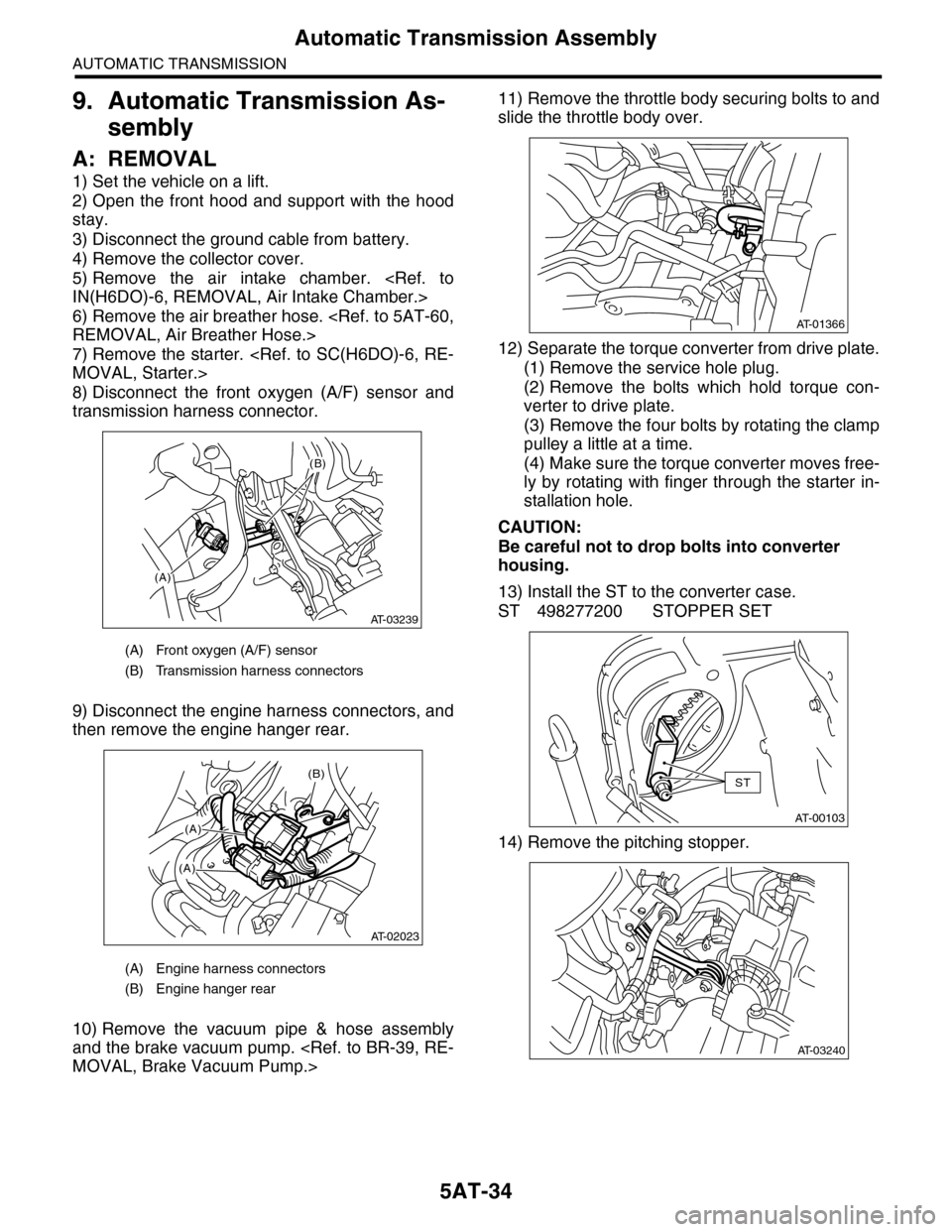
8) Disconnect the front oxygen (A/F) sensor and
transmission harness connector.
9) Disconnect the engine harness connectors, and
then remove the engine hanger rear.
10) Remove the vacuum pipe & hose assembly
and the brake vacuum pump.
11) Remove the throttle body securing bolts to and
slide the throttle body over.
12) Separate the torque converter from drive plate.
(1) Remove the service hole plug.
(2) Remove the bolts which hold torque con-
verter to drive plate.
(3) Remove the four bolts by rotating the clamp
pulley a little at a time.
(4) Make sure the torque converter moves free-
ly by rotating with finger through the starter in-
stallation hole.
CAUTION:
Be careful not to drop bolts into converter
housing.
13) Install the ST to the converter case.
ST 498277200 STOPPER SET
14) Remove the pitching stopper.
(A) Front oxygen (A/F) sensor
(B) Transmission harness connectors
(A) Engine harness connectors
(B) Engine hanger rear
(A)
(B)
AT-03239
(B)
(A)
(A)
AT-02023
AT-01366
AT-00103
ST
AT-03240