low oil pressure SUBARU TRIBECA 2009 1.G Service User Guide
[x] Cancel search | Manufacturer: SUBARU, Model Year: 2009, Model line: TRIBECA, Model: SUBARU TRIBECA 2009 1.GPages: 2453, PDF Size: 46.32 MB
Page 919 of 2453
PS-39
Pipe Assembly
POWER ASSISTED SYSTEM (POWER STEERING)
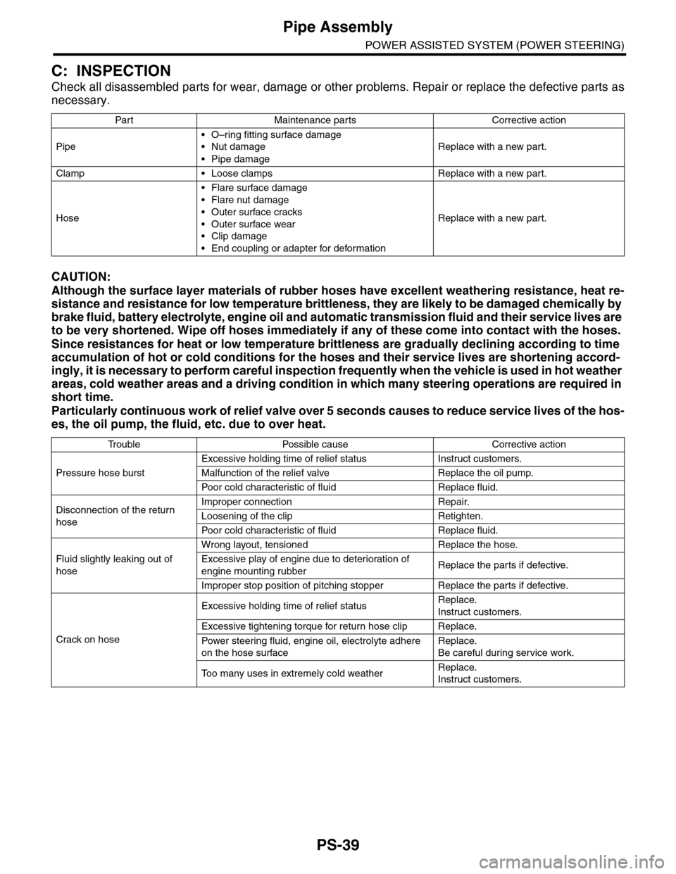
C: INSPECTION
Check all disassembled parts for wear, damage or other problems. Repair or replace the defective parts as
necessary.
CAUTION:
Although the surface layer materials of rubber hoses have excellent weathering resistance, heat re-
sistance and resistance for low temperature brittleness, they are likely to be damaged chemically by
brake fluid, battery electrolyte, engine oil and automatic transmission fluid and their service lives are
to be very shortened. Wipe off hoses immediately if any of these come into contact with the hoses.
Since resistances for heat or low temperature brittleness are gradually declining according to time
accumulation of hot or cold conditions for the hoses and their service lives are shortening accord-
ingly, it is necessary to perform careful inspection frequently when the vehicle is used in hot weather
areas, cold weather areas and a driving condition in which many steering operations are required in
short time.
Particularly continuous work of relief valve over 5 seconds causes to reduce service lives of the hos-
es, the oil pump, the fluid, etc. due to over heat.
Par t Maintenance par ts Corrective action
Pipe
•O–ring fitting surface damage
•Nut damage
•Pipe damage
Replace with a new part.
Clamp • Loose clamps Replace with a new part.
Hose
•Flare surface damage
•Flare nut damage
•Outer surface cracks
•Outer surface wear
•Clip damage
•End coupling or adapter for deformation
Replace with a new part.
Tr o u b l e P o s s i b l e c a u s e C o r r e c t i v e a c t i o n
Pressure hose burst
Excessive holding time of relief status Instruct customers.
Malfunction of the relief valve Replace the oil pump.
Poor cold character istic of fluid R eplace fluid.
Disconnection of the return
hose
Improper connection Repair.
Loosening of the clip Retighten.
Poor cold character istic of fluid R eplace fluid.
Fluid slightly leaking out of
hose
Wrong layout, tensioned Replace the hose.
Excessive play of engine due to deterioration of
engine mounting rubberReplace the parts if defective.
Improper stop position of pitching stopper Replace the parts if defective.
Crack on hose
Excessive holding time of relief statusReplace.
Instruct customers.
Excessive tightening torque for return hose clip Replace.
Power steer ing fluid, engine oil, electrolyte adhere
on the hose surface
Replace.
Be careful during service work.
To o m a n y u s e s i n e x t r e m e l y c o l d w e a t h e rReplace.
Instruct customers.
Page 922 of 2453
PS-42
Oil Pump
POWER ASSISTED SYSTEM (POWER STEERING)
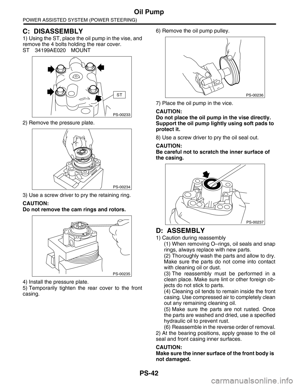
C: DISASSEMBLY
1) Using the ST, place the oil pump in the vise, and
remove the 4 bolts holding the rear cover.
ST 34199AE020 MOUNT
2) Remove the pressure plate.
3) Use a screw driver to pry the retaining ring.
CAUTION:
Do not remove the cam rings and rotors.
4) Install the pressure plate.
5) Temporarily tighten the rear cover to the front
casing.
6) Remove the oil pump pulley.
7) Place the oil pump in the vice.
CAUTION:
Do not place the oil pump in the vise directly.
Support the oil pump lightly using soft pads to
protect it.
8) Use a screw driver to pry the oil seal out.
CAUTION:
Be careful not to scratch the inner surface of
the casing.
D: ASSEMBLY
1) Caution during reassembly
(1) When removing O–rings, oil seals and snap
rings, always replace with new parts.
(2) Thoroughly wash the parts and allow to dry.
Make sure the parts do not come into contact
with cleaning oil or dust.
(3) The reassembly must be performed in a
clean place. Make sure lint or other foreign ob-
jects do not stick to parts.
(4) Cleaning oil tends to remain inside the front
casing. Use compressed air to completely clean
out any remaining cleaning oil.
(5) Make sure the parts are not rusted. Once
the parts are washed and dried, use a specified
hydraulic oil to prevent rust.
(6) Reassemble in the reverse order of removal.
2) At the bearing positions, apply grease to the oil
seal and front casing inner surfaces.
CAUTION:
Make sure the inner surface of the front body is
not damaged.
PS-00233
ST
PS-00234
PS-00235
PS-00236
PS-00237
Page 925 of 2453
PS-45
Oil Pump
POWER ASSISTED SYSTEM (POWER STEERING)
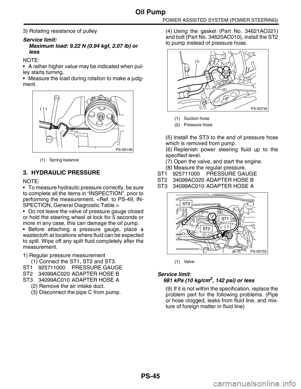
3) Rotating resistance of pulley
Service limit:
Maximum load: 9.22 N (0.94 kgf, 2.07 lb) or
less
NOTE:
•A rather higher value may be indicated when pul-
ley starts turning.
•Measure the load during rotation to make a judg-
ment.
3. HYDRAULIC PRESSURE
NOTE:
•To measure hydraulic pressure correctly, be sure
to complete all the items in “INSPECTION”, prior to
performing the measurement.
•Do not leave the valve of pressure gauge closed
or hold the steering wheel at lock for 5 seconds or
more in any case, this can damage the oil pump.
•Before attaching a pressure gauge, place a
wastecloth at locations where fluid can be expected
to spill. Wipe off any spilt fluid completely after the
measurement.
1) Regular pressure measurement
(1) Connect the ST1, ST2 and ST3.
ST1 925711000 PRESSURE GAUGE
ST2 34099AC020 ADAPTER HOSE B
ST3 34099AC010 ADAPTER HOSE A
(2) Remove the air intake duct.
(3) Disconnect the pipe C from pump.
(4) Using the gasket (Part No. 34621AC021)
and bolt (Part No. 34620AC010), install the ST2
to pump instead of pressure hose.
(5) Install the ST3 to the end of pressure hose
which is removed from pump.
(6) Replenish power steering fluid up to the
specified level.
(7) Open the valve, and start the engine.
(8) Measure the regular pressure.
ST1 925711000 PRESSURE GAUGE
ST2 34099AC020 ADAPTER HOSE B
ST3 34099AC010 ADAPTER HOSE A
Service limit:
981 kPa (10 kg/cm2, 142 psi) or less
(9) If it is not within the specification, replace the
problem part for the following problems. (Pipe
or hose clogged, leaks from fluid line, and mix-
ture of foreign matter in fluid line)
(1) Spring balance
PS-00148
(1) Suction hose
(2) Pressure hose
(1) Valve
PS-00736
(1)
(2)
PS-00152
Page 929 of 2453
PS-49
General Diagnostic Table
POWER ASSISTED SYSTEM (POWER STEERING)
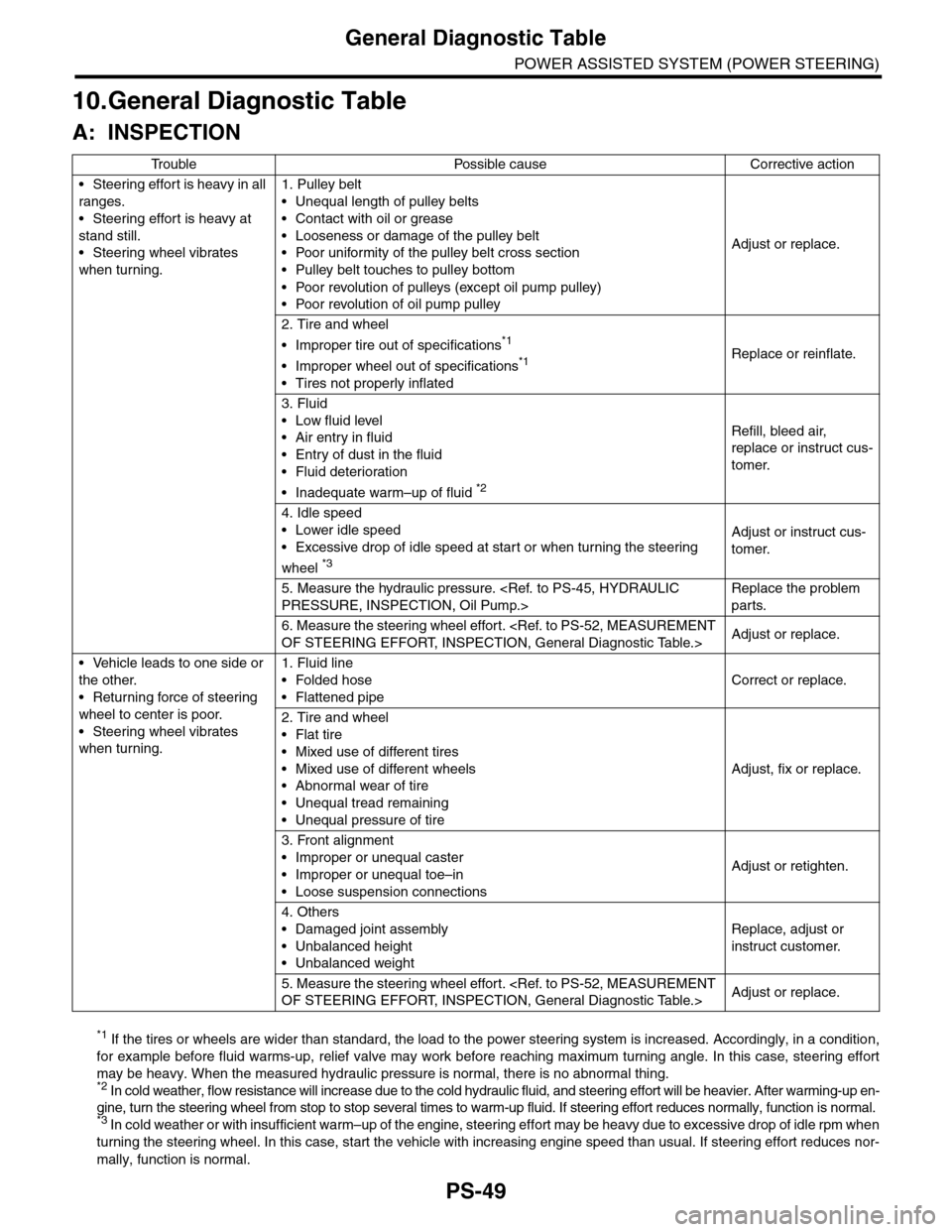
10.General Diagnostic Table
A: INSPECTION
*1 If the tires or wheels are wider than standard, the load to the power steering system is increased. Accordingly, in a condition,
for example before fluid warms-up, relief valve may work before reaching maximum turning angle. In this case, steering effort
may be heavy. When the measured hydraulic pressure is normal, there is no abnormal thing. *2 In cold weather, flow resistance will increase due to the cold hydraulic fluid, and steering effort will be heavier. After warming-up en-
gine, turn the steering wheel from stop to stop several times to warm-up fluid. If steering effort reduces normally, function is normal. *3 I n c o l d w e a t h e r o r w i t h i n s u f f i c i e n t w a r m – u p o f t h e e n g i n e , s t e e r i n g e f f o r t m a y b e h e a v y d u e t o e x c e s s i v e d r o p o f i d l e r p m w h en
turning the steering wheel. In this case, start the vehicle with increasing engine speed than usual. If steering effort reduces nor-
mally, function is normal.
Tr o u b l e P o s s i b l e c a u s e C o r r e c t i v e a c t i o n
•Steering effort is heavy in all
ranges.
•Steering effort is heavy at
stand still.
•Steering wheel vibrates
when turning.
1. Pulley belt
•Unequal length of pulley belts
•Contact with oil or grease
•Looseness or damage of the pulley belt
•Poor uniformity of the pulley belt cross section
•Pulley belt touches to pulley bottom
•Poor revolution of pulleys (except oil pump pulley)
•Poor revolution of oil pump pulley
Adjust or replace.
2. Tire and wheel
•Improper tire out of specifications*1
•Improper wheel out of specifications*1
•Tires not properly inflated
Replace or reinflate.
3. Fluid
•Low fluid level
•Air entry in fluid
•Entry of dust in the fluid
•Fluid deterioration
•Inadequate warm–up of fluid *2
Refill, bleed air,
replace or instruct cus-
tomer.
4. Idle speed
•Lower idle speed
•Excessive drop of idle speed at start or when turning the steering
wheel *3
Adjust or instruct cus-
tomer.
5. Measure the hydraulic pressure.
Replace the problem
parts.
6. Measure the steering wheel effort.
•Vehicle leads to one side or
the other.
•Returning force of steering
wheel to center is poor.
•Steering wheel vibrates
when turning.
1. Fluid line
•Folded hose
•Flattened pipe
Correct or replace.
2. Tire and wheel
•Flat tire
•Mixed use of different tires
•Mixed use of different wheels
•Abnormal wear of tire
•Unequal tread remaining
•Unequal pressure of tire
Adjust, fix or replace.
3. Front alignment
•Improper or unequal caster
•Improper or unequal toe–in
•Loose suspension connections
Adjust or retighten.
4. Others
•Damaged joint assembly
•Unbalanced height
•Unbalanced weight
Replace, adjust or
instruct customer.
5. Measure the steering wheel effort.
Page 1090 of 2453
VDC-9
VDC Control Module & Hydraulic Control Unit (VDCCM&H/U)
VEHICLE DYNAMICS CONTROL (VDC)
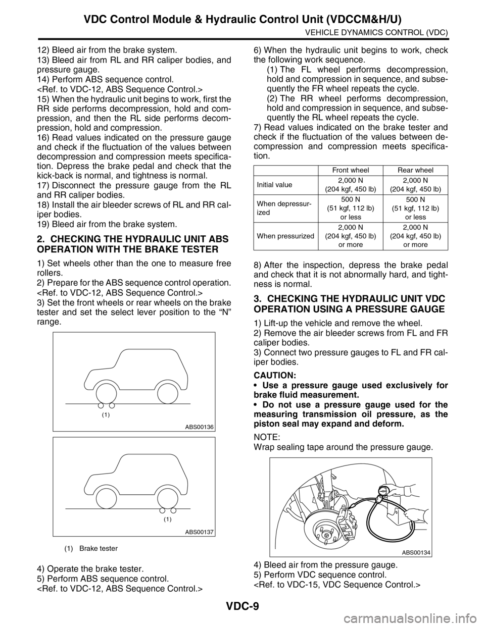
12) Bleed air from the brake system.
13) Bleed air from RL and RR caliper bodies, and
pressure gauge.
14) Perform ABS sequence control.
15) When the hydraulic unit begins to work, first the
RR side performs decompression, hold and com-
pression, and then the RL side performs decom-
pression, hold and compression.
16) Read values indicated on the pressure gauge
and check if the fluctuation of the values between
decompression and compression meets specifica-
tion. Depress the brake pedal and check that the
kick-back is normal, and tightness is normal.
17) Disconnect the pressure gauge from the RL
and RR caliper bodies.
18) Install the air bleeder screws of RL and RR cal-
iper bodies.
19) Bleed air from the brake system.
2. CHECKING THE HYDRAULIC UNIT ABS
OPERATION WITH THE BRAKE TESTER
1) Set wheels other than the one to measure free
rollers.
2) Prepare for the ABS sequence control operation.
3) Set the front wheels or rear wheels on the brake
tester and set the select lever position to the “N”
range.
4) Operate the brake tester.
5) Perform ABS sequence control.
6) When the hydraulic unit begins to work, check
the following work sequence.
(1) The FL wheel performs decompression,
hold and compression in sequence, and subse-
quently the FR wheel repeats the cycle.
(2) The RR wheel performs decompression,
hold and compression in sequence, and subse-
quently the RL wheel repeats the cycle.
7) Read values indicated on the brake tester and
check if the fluctuation of the values between de-
compression and compression meets specifica-
tion.
8) After the inspection, depress the brake pedal
and check that it is not abnormally hard, and tight-
ness is normal.
3. CHECKING THE HYDRAULIC UNIT VDC
OPERATION USING A PRESSURE GAUGE
1) Lift-up the vehicle and remove the wheel.
2) Remove the air bleeder screws from FL and FR
caliper bodies.
3) Connect two pressure gauges to FL and FR cal-
iper bodies.
CAUTION:
•Use a pressure gauge used exclusively for
brake fluid measurement.
•Do not use a pressure gauge used for the
measuring transmission oil pressure, as the
piston seal may expand and deform.
NOTE:
Wrap sealing tape around the pressure gauge.
4) Bleed air from the pressure gauge.
5) Perform VDC sequence control.
(1) Brake tester
ABS00136
(1)
ABS00137
(1)
Front wheelRear wheel
Initial value2,000 N
(204 kgf, 450 lb)
2,000 N
(204 kgf, 450 lb)
When depressur-
ized
500 N
(51 kgf, 112 lb)
or less
500 N
(51 kgf, 112 lb)
or less
When pressurized
2,000 N
(204 kgf, 450 lb)
or more
2,000 N
(204 kgf, 450 lb)
or more
ABS00134
Page 1149 of 2453
CO(H6DO)-30
Engine Cooling System Trouble in General
COOLING
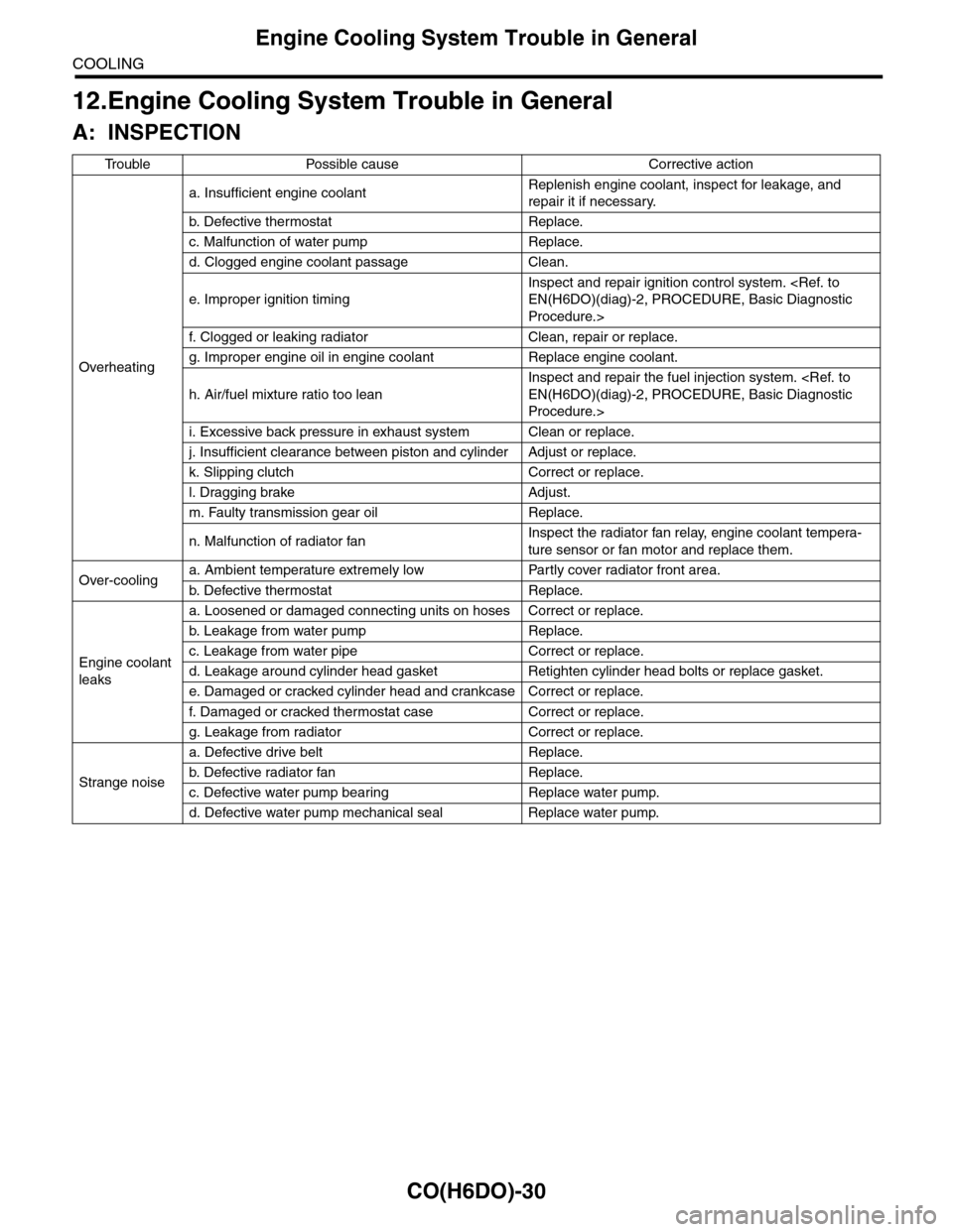
12.Engine Cooling System Trouble in General
A: INSPECTION
Tr o u b l e P o s s i b l e c a u s e C o r r e c t i v e a c t i o n
Overheating
a. Insufficient engine coolantReplenish engine coolant, inspect for leakage, and
repair it if necessary.
b. De fe c ti ve t he r mo st a t Rep la c e.
c. Malfunction of water pump Replace.
d. Clogged engine coolant passage Clean.
e. Improper ignition timing
Inspect and repair ignition control system.
Procedure.>
f. Clogged or leaking radiator Clean, repair or replace.
g. Improper engine oil in engine coolant Replace engine coolant.
h. Air/fuel mixture ratio too lean
Inspect and repair the fuel injection system.
Procedure.>
i. Excessive back pressure in exhaust system Clean or replace.
j. Insufficient clearance between piston and cylinder Adjust or replace.
k. Slipping clutch Correct or replace.
l. Dragging brake Adjust.
m. Faulty transmission gear oil Replace.
n. Malfunction of radiator fanInspect the radiator fan relay, engine coolant tempera-
ture sensor or fan motor and replace them.
Over-coolinga. Ambient temperature extremely low Partly cover radiator front area.
b. De fe c ti ve t he r mo st a t Rep la c e.
Engine coolant
leaks
a. Loosened or damaged connecting units on hoses Correct or replace.
b. L ea k ag e f r o m wat e r pu mp Rep la c e.
c. Leakage from water pipe Correct or replace.
d. Leakage around cylinder head gasket Retighten cylinder head bolts or replace gasket.
e. Damaged or cracked cylinder head and crankcase Correct or replace.
f. Damaged or cracked ther mostat case Correct or replace.
g. Leakage from radiator Correct or replace.
Strange noise
a. Defective drive belt Replace.
b. De fe c ti ve ra di a t or fan Rep la c e.
c. Defective water pump bearing Replace water pump.
d. Defective water pump mechanical seal Replace water pump.
Page 1165 of 2453
EN(H6DO)(diag)-4
Check List for Interview
ENGINE (DIAGNOSTICS)
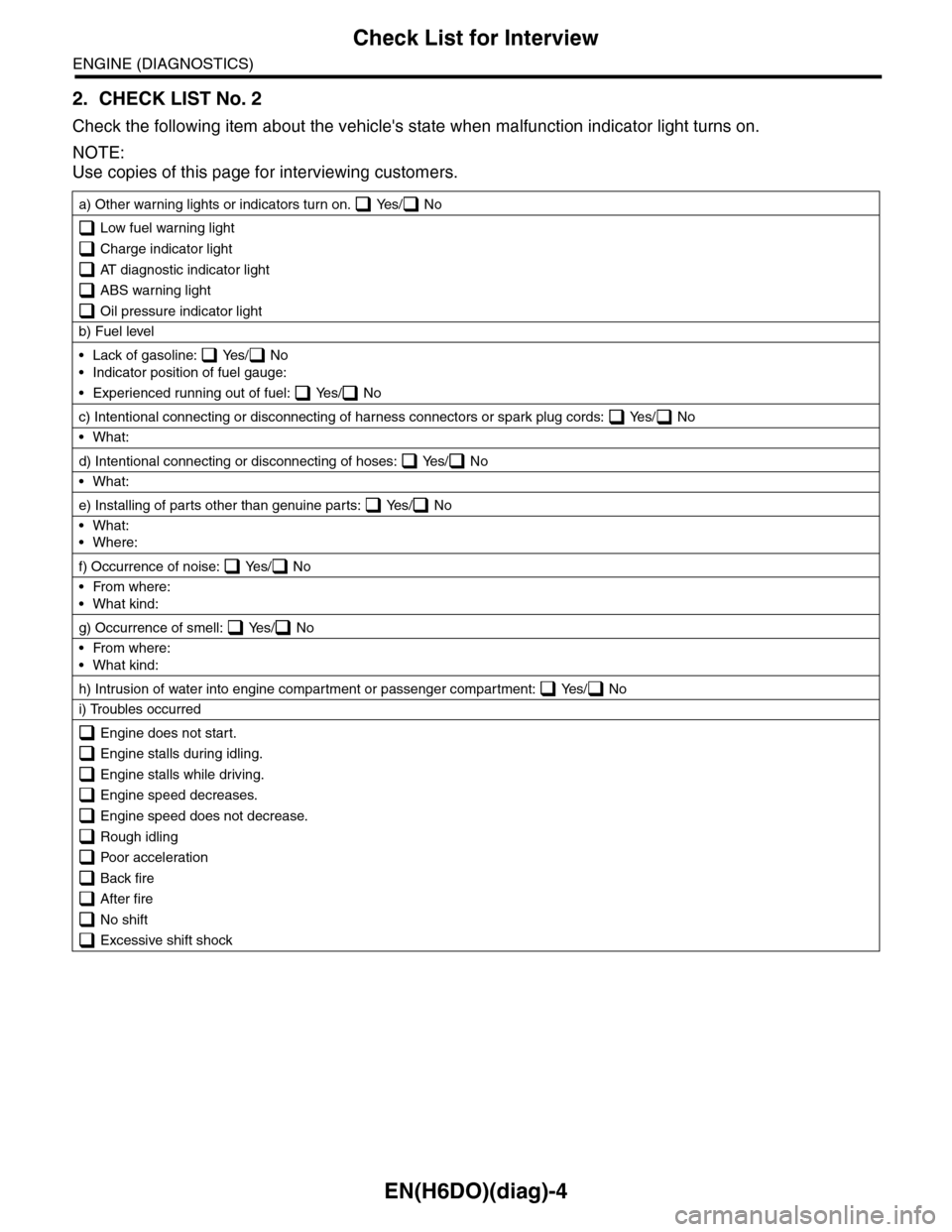
2. CHECK LIST No. 2
Check the following item about the vehicle's state when malfunction indicator light turns on.
NOTE:
Use copies of this page for interviewing customers.
a) Other warning lights or indicators turn on. Yes/ No
Low fuel warning light
Charge indicator light
AT diagnostic indicator light
ABS warning light
Oil pressure indicator light
b) Fuel level
•Lack of gasoline: Yes/ No
•Indicator position of fuel gauge:
•Experienced running out of fuel: Yes/ No
c) Intentional connecting or disconnecting of harness connectors or spark plug cords: Yes/ No
•What:
d) Intentional connecting or disconnecting of hoses: Yes/ No
•What:
e) Installing of parts other than genuine parts: Yes/ No
•What:
•Where:
f) Occurrence of noise: Yes/ No
•From where:
•What kind:
g) Occurrence of smell: Yes/ No
•From where:
•What kind:
h) Intrusion of water into engine compartment or passenger compartment: Yes/ No
i) Troubles occurred
Engine does not start.
Engine stalls during idling.
Engine stalls while driving.
Engine speed decreases.
Engine speed does not decrease.
Rough idling
Poor acceleration
Back fire
After fire
No shift
Excessive shift shock
Page 1170 of 2453
EN(H6DO)(diag)-9
Electrical Component Location
ENGINE (DIAGNOSTICS)
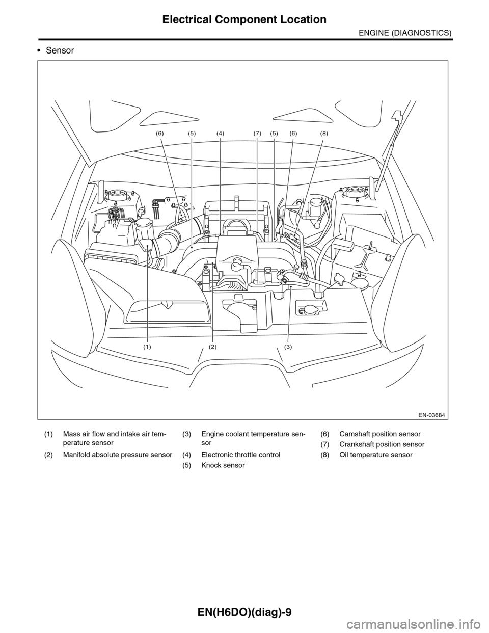
•Sensor
(1) Mass air flow and intake air tem-
perature sensor
(3) Engine coolant temperature sen-
sor
(6) Camshaft position sensor
(7) Crankshaft position sensor
(2) Manifold absolute pressure sensor (4) Electronic throttle control (8) Oil temperature sensor
(5) Knock sensor
EN-03684
(6)(6) (8)
(3)(2)
(7)
(1)
(4) (5)(5)
Page 1174 of 2453
EN(H6DO)(diag)-13
Electrical Component Location
ENGINE (DIAGNOSTICS)
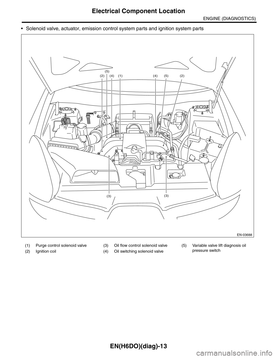
•Solenoid valve, actuator, emission control system parts and ignition system parts
(1) Purge control solenoid valve (3) Oil flow control solenoid valve (5)
Va r i a b l e va l v e l i f t d i a g n o s i s o i l
pressure switch(2) Ignition coil (4) Oil switching solenoid valve
EN-03688
(5) (2)
(3)
(2) (1)
(3)
(4) (4)(5)
Page 1179 of 2453
EN(H6DO)(diag)-18
Engine Control Module (ECM) I/O Signal
ENGINE (DIAGNOSTICS)
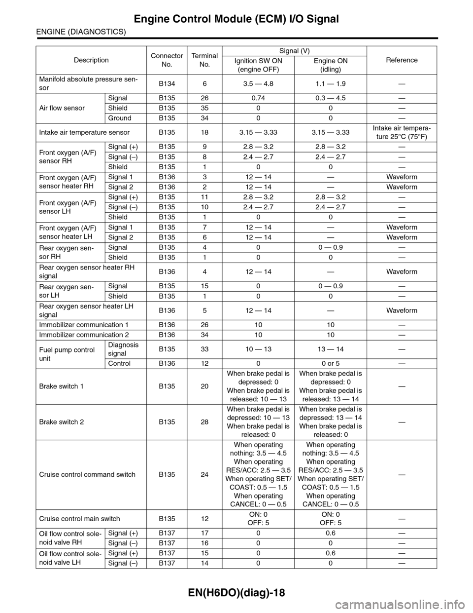
Manifold absolute pressure sen-
sorB134 6 3.5 — 4.8 1.1 — 1.9 —
Air flow sensor
Signal B135 26 0.74 0.3 — 4.5 —
Shield B135 35 0 0 —
Ground B135 34 0 0 —
Intake air temperature sensor B135 18 3.15 — 3.33 3.15 — 3.33Intake air tempera-
ture 25°C (75°F)
Fr o nt ox yg e n ( A / F)
sensor RH
Signal (+) B135 9 2.8 — 3.2 2.8 — 3.2 —
Signal (–) B135 8 2.4 — 2.7 2.4 — 2.7 —
Shield B135 1 0 0 —
Fr o nt ox yg e n ( A / F)
sensor heater RH
Signal 1 B136 3 12 — 14 — Waveform
Signal 2 B136 2 12 — 14 — Waveform
Fr o nt ox yg e n ( A / F)
sensor LH
Signal (+) B135 11 2.8 — 3.2 2.8 — 3.2 —
Signal (–) B135 10 2.4 — 2.7 2.4 — 2.7 —
Shield B135 1 0 0 —
Fr o nt ox yg e n ( A / F)
sensor heater LH
Signal 1 B135 7 12 — 14 — Waveform
Signal 2 B135 6 12 — 14 — Waveform
Rear oxygen sen-
sor RH
Signal B135 4 0 0 — 0.9 —
Shield B135 1 0 0 —
Rear oxygen sensor heater RH
signalB136 4 12 — 14 — Waveform
Rear oxygen sen-
sor LH
Signal B135 15 0 0 — 0.9 —
Shield B135 1 0 0 —
Rear oxygen sensor heater LH
signalB136 5 12 — 14 — Waveform
Immobilizer communication 1 B136 26 10 10 —
Immobilizer communication 2 B136 34 10 10 —
Fuel pump control
unit
Diagnosis
signalB135 33 10 — 13 13 — 14 —
Control B136 12 0 0 or 5 —
Brake switch 1 B135 20
When brake pedal is
depressed: 0
When brake pedal is
released: 10 — 13
When brake pedal is
depressed: 0
When brake pedal is
released: 13 — 14
—
Brake switch 2 B135 28
When brake pedal is
depressed: 10 — 13
When brake pedal is
released: 0
When brake pedal is
depressed: 13 — 14
When brake pedal is
released: 0
—
Cruise control command switch B135 24
When operating
nothing: 3.5 — 4.5
When operating
RES/ACC: 2.5 — 3.5
When operating SET/
COAST: 0.5 — 1.5
When operating
CANCEL: 0 — 0.5
When operating
nothing: 3.5 — 4.5
When operating
RES/ACC: 2.5 — 3.5
When operating SET/
COAST: 0.5 — 1.5
When operating
CANCEL: 0 — 0.5
—
Cruise control main switch B135 12ON: 0
OFF: 5
ON: 0
OFF: 5—
Oil flow control sole-
noid valve RH
Signal (+) B137 17 0 0.6 —
Signal (–) B137 16 0 0 —
Oil flow control sole-
noid valve LH
Signal (+) B137 15 0 0.6 —
Signal (–) B137 14 0 0 —
DescriptionConnector
No.
Te r m i n a l
No.
Signal (V)
ReferenceIgnition SW ON
(engine OFF)
Engine ON
(idling)