actuator SUBARU TRIBECA 2009 1.G Service Owner's Manual
[x] Cancel search | Manufacturer: SUBARU, Model Year: 2009, Model line: TRIBECA, Model: SUBARU TRIBECA 2009 1.GPages: 2453, PDF Size: 46.32 MB
Page 406 of 2453
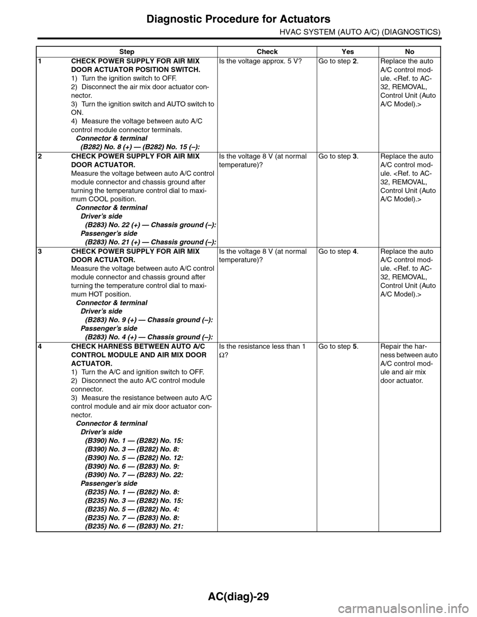
AC(diag)-29
Diagnostic Procedure for Actuators
HVAC SYSTEM (AUTO A/C) (DIAGNOSTICS)
Step Check Yes No
1CHECK POWER SUPPLY FOR AIR MIX
DOOR ACTUATOR POSITION SWITCH.
1) Turn the ignition switch to OFF.
2) Disconnect the air mix door actuator con-
nector.
3) Turn the ignition switch and AUTO switch to
ON.
4) Measure the voltage between auto A/C
control module connector terminals.
Connector & terminal
(B282) No. 8 (+) — (B282) No. 15 (–):
Is the voltage approx. 5 V? Go to step 2.Replace the auto
A/C control mod-
ule.
Control Unit (Auto
A/C Model).>
2CHECK POWER SUPPLY FOR AIR MIX
DOOR ACTUATOR.
Measure the voltage between auto A/C control
module connector and chassis ground after
turning the temperature control dial to maxi-
mum COOL position.
Connector & terminal
Driver’s side
(B283) No. 22 (+) — Chassis ground (–):
Passenger’s side
(B283) No. 21 (+) — Chassis ground (–):
Is the voltage 8 V (at normal
temperature)?
Go to step 3.Replace the auto
A/C control mod-
ule.
Control Unit (Auto
A/C Model).>
3CHECK POWER SUPPLY FOR AIR MIX
DOOR ACTUATOR.
Measure the voltage between auto A/C control
module connector and chassis ground after
turning the temperature control dial to maxi-
mum HOT position.
Connector & terminal
Driver’s side
(B283) No. 9 (+) — Chassis ground (–):
Passenger’s side
(B283) No. 4 (+) — Chassis ground (–):
Is the voltage 8 V (at normal
temperature)?
Go to step 4.Replace the auto
A/C control mod-
ule.
Control Unit (Auto
A/C Model).>
4CHECK HARNESS BETWEEN AUTO A/C
CONTROL MODULE AND AIR MIX DOOR
ACTUATOR.
1) Turn the A/C and ignition switch to OFF.
2) Disconnect the auto A/C control module
connector.
3) Measure the resistance between auto A/C
control module and air mix door actuator con-
nector.
Connector & terminal
Driver’s side
(B390) No. 1 — (B282) No. 15:
(B390) No. 3 — (B282) No. 8:
(B390) No. 5 — (B282) No. 12:
(B390) No. 6 — (B283) No. 9:
(B390) No. 7 — (B283) No. 22:
Passenger’s side
(B235) No. 1 — (B282) No. 8:
(B235) No. 3 — (B282) No. 15:
(B235) No. 5 — (B282) No. 4:
(B235) No. 7 — (B283) No. 8:
(B235) No. 6 — (B283) No. 21:
Is the resistance less than 1
Ω?
Go to step 5.Repair the har-
ness between auto
A/C control mod-
ule and air mix
door actuator.
Page 407 of 2453
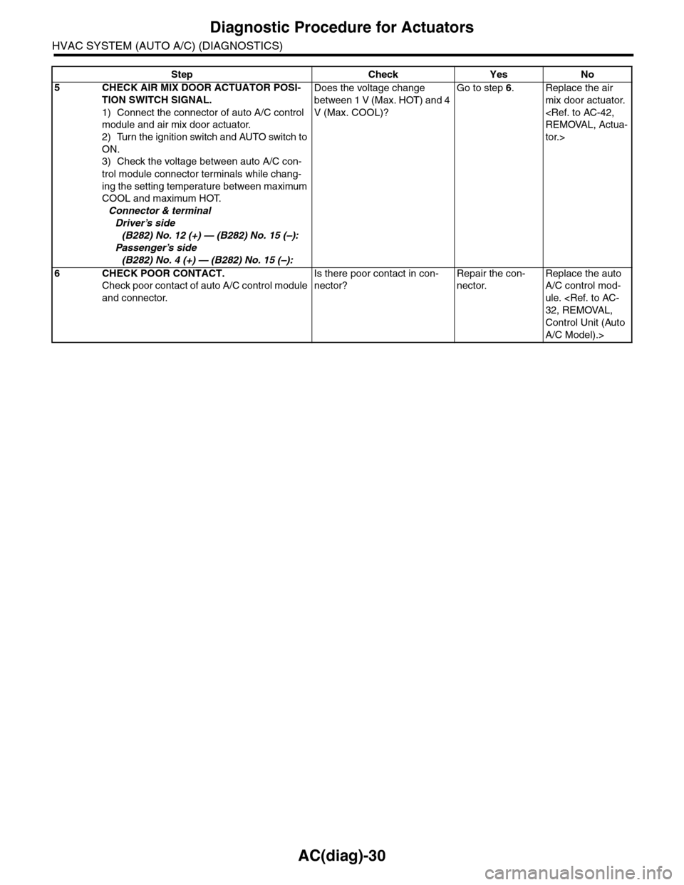
AC(diag)-30
Diagnostic Procedure for Actuators
HVAC SYSTEM (AUTO A/C) (DIAGNOSTICS)
5CHECK AIR MIX DOOR ACTUATOR POSI-
TION SWITCH SIGNAL.
1) Connect the connector of auto A/C control
module and air mix door actuator.
2) Turn the ignition switch and AUTO switch to
ON.
3) Check the voltage between auto A/C con-
trol module connector terminals while chang-
ing the setting temperature between maximum
COOL and maximum HOT.
Connector & terminal
Driver’s side
(B282) No. 12 (+) — (B282) No. 15 (–):
Passenger’s side
(B282) No. 4 (+) — (B282) No. 15 (–):
Does the voltage change
between 1 V (Max. HOT) and 4
V (Max. COOL)?
Go to step 6.Replace the air
mix door actuator.
tor.>
6CHECK POOR CONTACT.
Check poor contact of auto A/C control module
and connector.
Is there poor contact in con-
nector?
Repair the con-
nector.
Replace the auto
A/C control mod-
ule.
Control Unit (Auto
A/C Model).>
Step Check Yes No
Page 416 of 2453
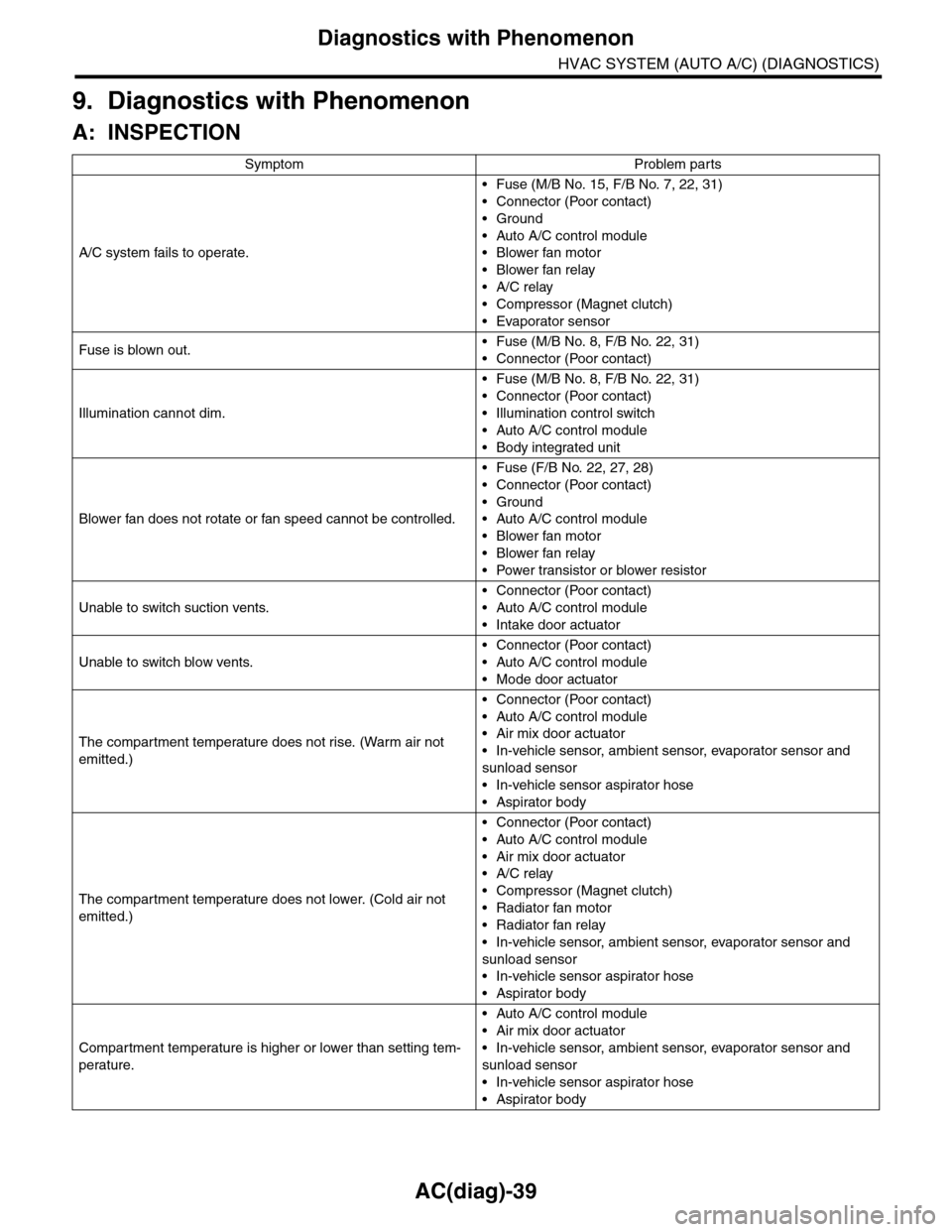
AC(diag)-39
Diagnostics with Phenomenon
HVAC SYSTEM (AUTO A/C) (DIAGNOSTICS)
9. Diagnostics with Phenomenon
A: INSPECTION
Symptom Problem parts
A/C system fails to operate.
•Fuse (M/B No. 15, F/B No. 7, 22, 31)
•Connector (Poor contact)
•Ground
•Auto A/C control module
•Blower fan motor
•Blower fan relay
•A/C relay
•Compressor (Magnet clutch)
•Evaporator sensor
Fuse is blown out.•Fuse (M/B No. 8, F/B No. 22, 31)
•Connector (Poor contact)
Illumination cannot dim.
•Fuse (M/B No. 8, F/B No. 22, 31)
•Connector (Poor contact)
•Illumination control switch
•Auto A/C control module
•Body integrated unit
Blower fan does not rotate or fan speed cannot be controlled.
•Fuse (F/B No. 22, 27, 28)
•Connector (Poor contact)
•Ground
•Auto A/C control module
•Blower fan motor
•Blower fan relay
•Power transistor or blower resistor
Unable to switch suction vents.
•Connector (Poor contact)
•Auto A/C control module
•Intake door actuator
Unable to switch blow vents.
•Connector (Poor contact)
•Auto A/C control module
•Mode door actuator
The compar tment temperature does not rise. (Warm air not
emitted.)
•Connector (Poor contact)
•Auto A/C control module
•Air mix door actuator
•In-vehicle sensor, ambient sensor, evaporator sensor and
sunload sensor
•In-vehicle sensor aspirator hose
•Aspirator body
The compar tment temperature does not lower. (Cold air not
emitted.)
•Connector (Poor contact)
•Auto A/C control module
•Air mix door actuator
•A/C relay
•Compressor (Magnet clutch)
•Radiator fan motor
•Radiator fan relay
•In-vehicle sensor, ambient sensor, evaporator sensor and
sunload sensor
•In-vehicle sensor aspirator hose
•Aspirator body
Compartment temperature is higher or lower than setting tem-
perature.
•Auto A/C control module
•Air mix door actuator
•In-vehicle sensor, ambient sensor, evaporator sensor and
sunload sensor
•In-vehicle sensor aspirator hose
•Aspirator body
Page 417 of 2453
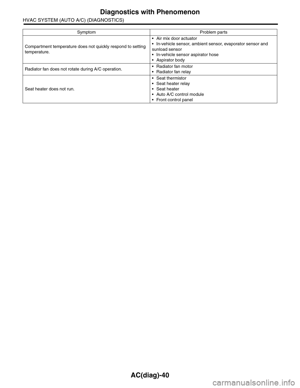
AC(diag)-40
Diagnostics with Phenomenon
HVAC SYSTEM (AUTO A/C) (DIAGNOSTICS)
Compartment temperature does not quickly respond to setting
temperature.
•Air mix door actuator
•In-vehicle sensor, ambient sensor, evaporator sensor and
sunload sensor
•In-vehicle sensor aspirator hose
•Aspirator body
Radiator fan does not rotate during A/C operation.•Radiator fan motor
•Radiator fan relay
Seat heater does not run.
•Seat thermistor
•Seat heater relay
•Seat heater
•Auto A/C control module
•Front control panel
Symptom Problem parts
Page 471 of 2453
LAN(diag)-15
Subaru Select Monitor
LAN SYSTEM (DIAGNOSTICS)
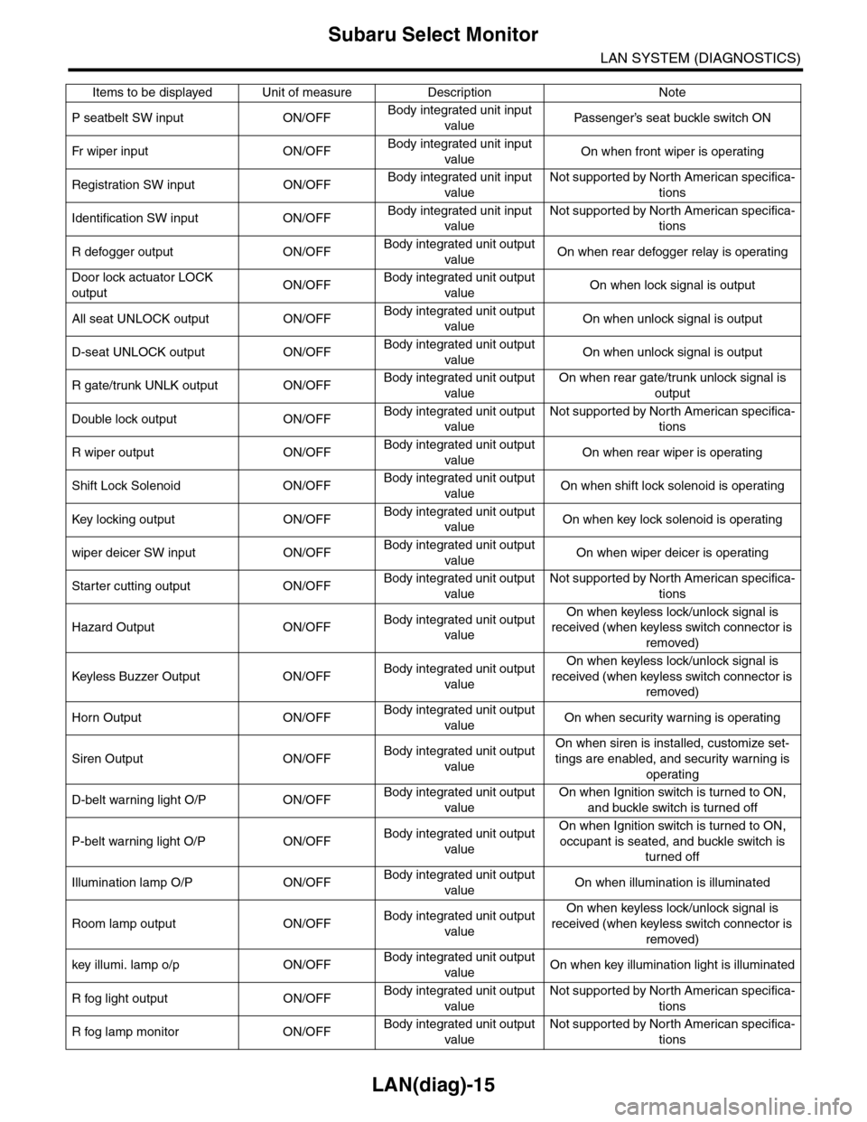
P seatbelt SW input ON/OFFBody integrated unit input
valuePa s se ng e r ’s se at bu ckl e sw it c h ON
Fr wi pe r in p ut O N/O FFBody integrated unit input
valueOn when front wiper is operating
Registration SW input ON/OFFBody integrated unit input
value
Not supported by North American specifica-
tions
Identification SW input ON/OFFBody integrated unit input
value
Not supported by North American specifica-
tions
R defogger output ON/OFFBody integrated unit output
valueOn when rear defogger relay is operating
Door lock actuator LOCK
outputON/OFFBody integrated unit output
valueOn when lock signal is output
All seat UNLOCK output ON/OFFBody integrated unit output
valueOn when unlock signal is output
D-seat UNLOCK output ON/OFFBody integrated unit output
valueOn when unlock signal is output
R gate/trunk UNLK output ON/OFFBody integrated unit output
value
On when rear gate/trunk unlock signal is
output
Double lock output ON/OFFBody integrated unit output
value
Not supported by North American specifica-
tions
R wiper output ON/OFFBody integrated unit output
valueOn when rear wiper is operating
Shift Lock Solenoid ON/OFFBody integrated unit output
valueOn when shift lock solenoid is operating
Key locking output ON/OFFBody integrated unit output
valueOn when key lock solenoid is operating
wiper deicer SW input ON/OFFBody integrated unit output
valueOn when wiper deicer is operating
Starter cutting output ON/OFFBody integrated unit output
value
Not supported by North American specifica-
tions
Hazard Output ON/OFFBody integrated unit output
value
On when keyless lock/unlock signal is
received (when keyless switch connector is
removed)
Keyless Buzzer Output ON/OFFBody integrated unit output
value
On when keyless lock/unlock signal is
received (when keyless switch connector is
removed)
Horn Output ON/OFFBody integrated unit output
valueOn when security warning is operating
Siren Output ON/OFFBody integrated unit output
value
On when siren is installed, customize set-
tings are enabled, and security warning is
operating
D-belt warning light O/P ON/OFFBody integrated unit output
value
On when Ignition switch is turned to ON,
and buckle switch is turned off
P-belt warning light O/P ON/OFFBody integrated unit output
value
On when Ignition switch is turned to ON,
occupant is seated, and buckle switch is
turned off
Illumination lamp O/P ON/OFFBody integrated unit output
valueOn when illumination is illuminated
Room lamp output ON/OFFBody integrated unit output
value
On when keyless lock/unlock signal is
received (when keyless switch connector is
removed)
key illumi. lamp o/p ON/OFFBody integrated unit output
valueOn when key illumination light is illuminated
R fog light output ON/OFFBody integrated unit output
value
Not supported by North American specifica-
tions
R fog lamp monitor ON/OFFBody integrated unit output
value
Not supported by North American specifica-
tions
Items to be displayed Unit of measure Description Note
Page 480 of 2453
LAN(diag)-24
Subaru Select Monitor
LAN SYSTEM (DIAGNOSTICS)
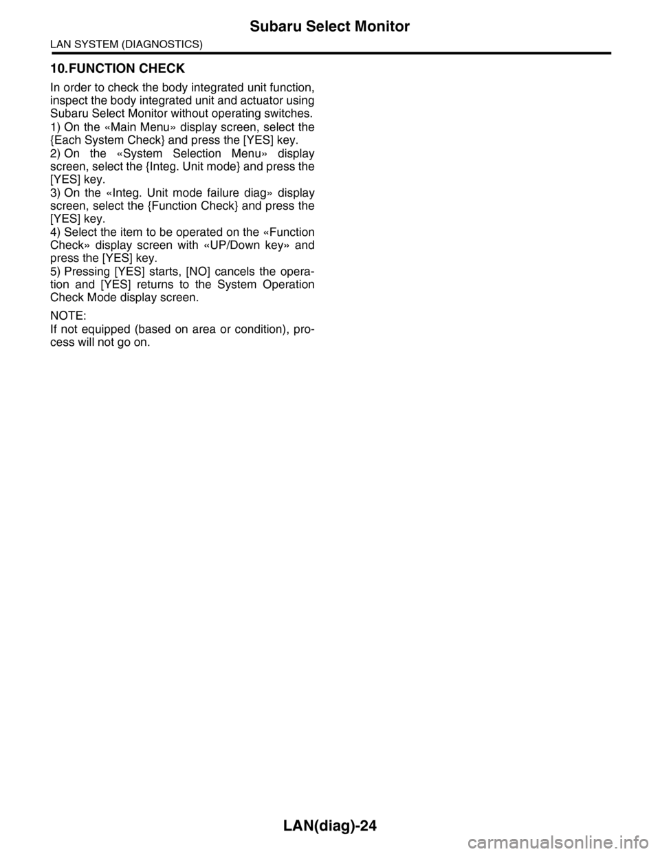
10.FUNCTION CHECK
In order to check the body integrated unit function,
inspect the body integrated unit and actuator using
Subaru Select Monitor without operating switches.
1) On the «Main Menu» display screen, select the
{Each System Check} and press the [YES] key.
2) On the «System Selection Menu» display
screen, select the {Integ. Unit mode} and press the
[YES] key.
3) On the «Integ. Unit mode failure diag» display
screen, select the {Function Check} and press the
[YES] key.
4) Select the item to be operated on the «Function
Check» display screen with «UP/Down key» and
press the [YES] key.
5) Pressing [YES] starts, [NO] cancels the opera-
tion and [YES] returns to the System Operation
Check Mode display screen.
NOTE:
If not equipped (based on area or condition), pro-
cess will not go on.
Page 532 of 2453
LAN(diag)-76
General Diagnostic Table
LAN SYSTEM (DIAGNOSTICS)
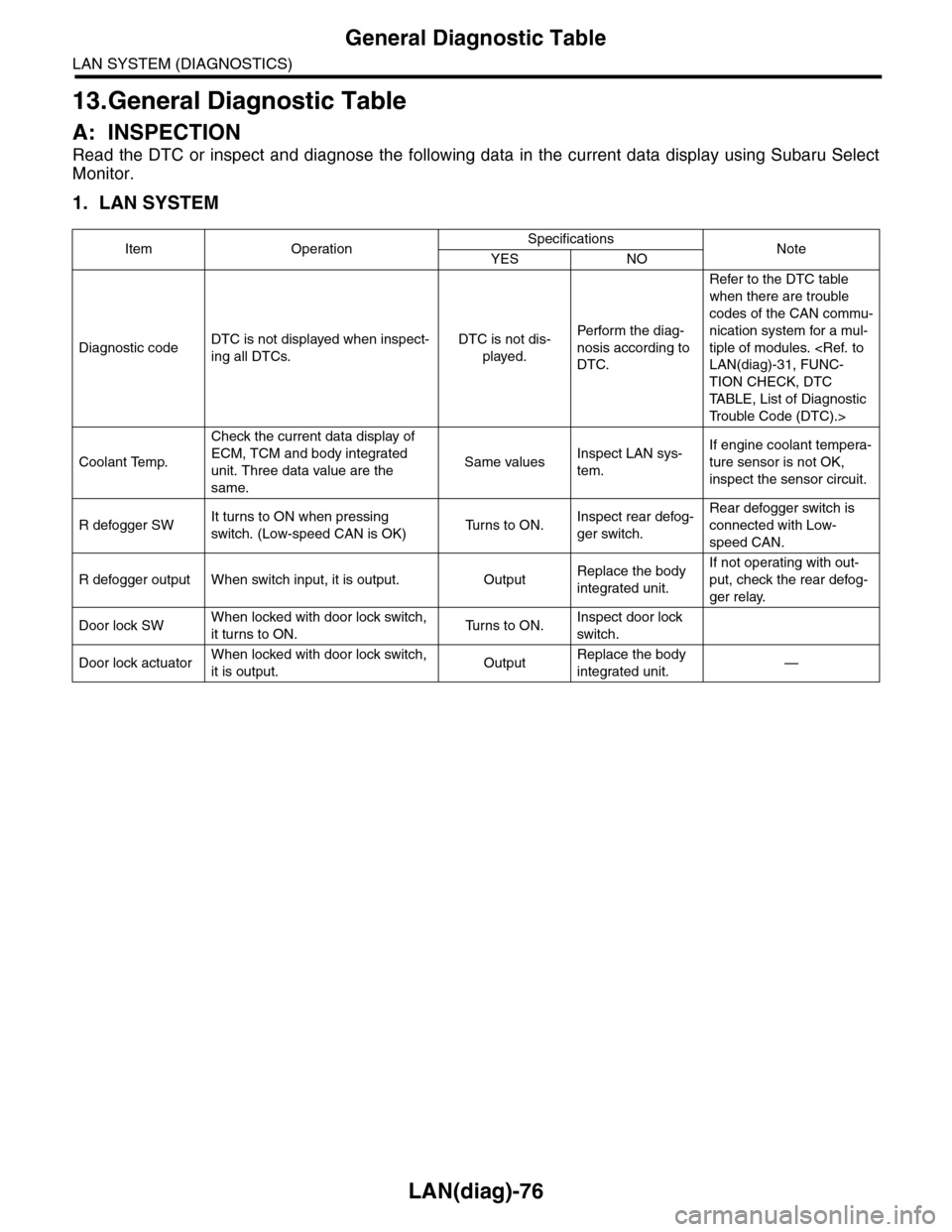
13.General Diagnostic Table
A: INSPECTION
Read the DTC or inspect and diagnose the following data in the current data display using Subaru Select
Monitor.
1. LAN SYSTEM
Item OperationSpecificationsNoteYES NO
Diagnostic codeDTC is not displayed when inspect-
ing all DTCs.
DTC is not dis-
played.
Perfor m the diag-
nosis according to
DTC.
Refer to the DTC table
when there are trouble
codes of the CAN commu-
nication system for a mul-
tiple of modules.
TION CHECK, DTC
TA B L E , L i s t o f D i a g n o s t i c
Tr o u b l e C o d e ( D T C ) . >
Coolant Temp.
Check the current data display of
ECM, TCM and body integrated
unit. Three data value are the
same.
Same valuesInspect LAN sys-
tem.
If engine coolant tempera-
ture sensor is not OK,
inspect the sensor circuit.
R defogger SWIt turns to ON when pressing
switch. (Low-speed CAN is OK)Tu r n s t o O N .Inspect rear defog-
ger switch.
Rear defogger switch is
connected with Low-
speed CAN.
R defogger output When switch input, it is output. OutputReplace the body
integrated unit.
If not operating with out-
put, check the rear defog-
ger relay.
Door lock SWWhen locked with door lock switch,
it turns to ON.Tu r n s t o O N .Inspect door lock
switch.
Door lock actuatorWhen locked with door lock switch,
it is output.OutputReplace the body
integrated unit.—
Page 533 of 2453
LAN(diag)-77
General Diagnostic Table
LAN SYSTEM (DIAGNOSTICS)
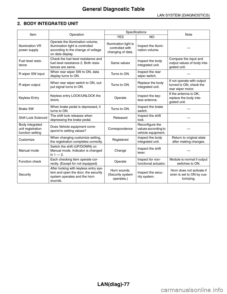
2. BODY INTEGRATED UNIT
Item OperationSpecificationsNoteYES NO
Illumination VR
power supply
Operate the illumination volume,
illumination light is controlled
according to the change of voltage
on data display.
Illumination light is
controlled with
changing of data.
Inspect the illumi-
nation volume.—
Fuel level resis-
tance
Check the fuel level resistance and
fuel level resistance 2. Both resis-
tances are same.
Same valuesInspect the body
integrated unit.
Compare the input and
output values of body inte-
grated unit.
R wiper SW inputWhen rear wiper SW to ON, data
display turns to ON.Tu r n s t o O N .Inspect the rear
wiper switch.—
R wiper outputWhen rear wiper switch to ON, out-
put signal turns to ON.Tu r n s t o O N .Replace the body
integrated unit.
If not operate with output
turned to ON, check the
rear wiper motor.
Keyless Entr yKeyless entr y LOCK/UNLOCK the
doors.OperateInspect the key-
less antenna.
If the antenna is OK,
replace the body inte-
grated unit.
Brake SWWhen brake pedal is depressed, it
turns to ON.Tu r n s t o O N .Inspect the brake
switch.—
Shift Lock SolenoidThe shift lock releases when
depressing the brake pedal.ReleasedInspect the shift
lock.—
Body integrated
unit registration
function setting
Does Vehicle equipment corre-
spond to setting values?Correspondence
Reconfigure the
values according to
vehicle equipment.
—
CustomizeWhen changing customize setting,
the registration completes correctly.RegisteredInspect the body
integrated unit.
Return to original state
after making changes.
Manual mode
Switch the shift (UP/DOWN) on
Manual mode. Indicator is changed
in 1 — 2.
ChangeInspect the shift
lever.—
Function checkEach checking item operate cor-
rectly. (Except for not equipped)OperateInspect for non-
functional actuator.
Module is normal if output
switches to ON.
Security
After locking with keyless entry sys-
tem and open the door, the security
system operates and the horn
sounds.
Horn sounds.
(Security system
operates.)
Inspect the secu-
rity system.
Horn does not activate if
siren is set to ON by cus-
tomizing.
Page 631 of 2453
SL-2
General Description
SECURITY AND LOCKS
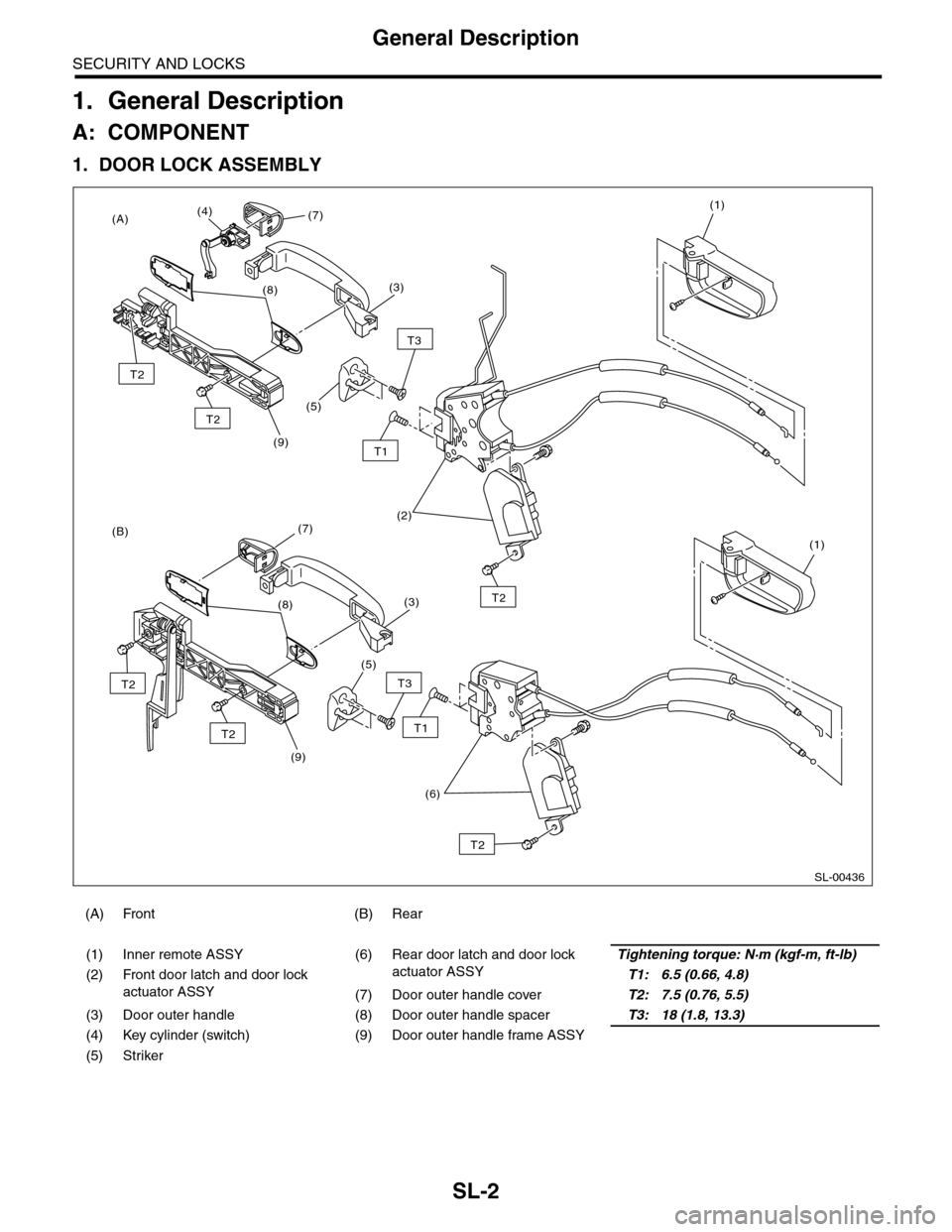
1. General Description
A: COMPONENT
1. DOOR LOCK ASSEMBLY
(A) Front (B) Rear
(1) Inner remote ASSY (6) Rear door latch and door lock
actuator ASSY
Tightening torque: N·m (kgf-m, ft-lb)
(2) Front door latch and door lock
actuator ASSY
T1: 6.5 (0.66, 4.8)
(7) Door outer handle coverT2: 7.5 (0.76, 5.5)
(3) Door outer handle (8) Door outer handle spacerT3: 18 (1.8, 13.3)
(4) Key cylinder (switch) (9) Door outer handle frame ASSY
(5) Striker
SL-00436
(9)
T1
(B)
(A)
T3
(5)
(9)
(2)
(1)
(1)
T3
(5)
(6)
T2
T1
(3)
(7)(4)
(8)
T2
(3)
(7)
T2
T2
(8)T2
T2
Page 632 of 2453
SL-3
General Description
SECURITY AND LOCKS
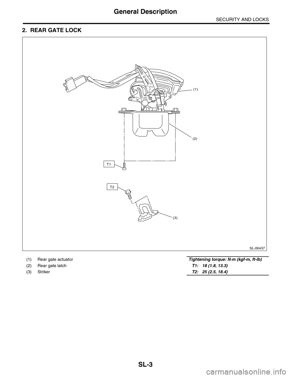
2. REAR GATE LOCK
(1) Rear gate actuator Tightening torque: N·m (kgf-m, ft-lb)
(2) Rear gate latch T1: 18 (1.8, 13.3)
(3) Striker T2: 25 (2.5, 18.4)
SL-00437
T2
(1)
(2)
(3)
T1