SUBARU TRIBECA 2009 1.G Service Workshop Manual
Manufacturer: SUBARU, Model Year: 2009, Model line: TRIBECA, Model: SUBARU TRIBECA 2009 1.GPages: 2453, PDF Size: 46.32 MB
Page 351 of 2453
AC-25
Compressor Oil
HVAC SYSTEM (HEATER, VENTILATOR AND A/C)
6. Compressor Oil
A: PROCEDURE
NOTE:
Before making repairs, perform the oil return oper-
ation to return the compressor oil in circulation with
the refrigerant to the compressor.
1) Increase the engine to 1,500 rpm.
2) Turn on the A/C switch.
3) Turn the temperature control switch to MAX
COOL.
4) Put in RECIRC position.
5) Turn the blower control switch to HI. (For models
with rear coolers, also turn the rear cooler fan
switch to HI)
6) Leave in this condition for 10 minutes.
B: REPLACEMENT
NOTE:
•If a component has been replaced, add an ap-
propriate amount of compressor oil (same as the
amount of remaining oil in removed component).
•When replacing the compressor, the new com-
pressor will already have the specified amount of
oil in it. Install the new compressor after removing
the same amount of oil that is remaining in the com-
pressor removed.
Page 352 of 2453
AC-26
Blower Motor Unit Assembly
HVAC SYSTEM (HEATER, VENTILATOR AND A/C)
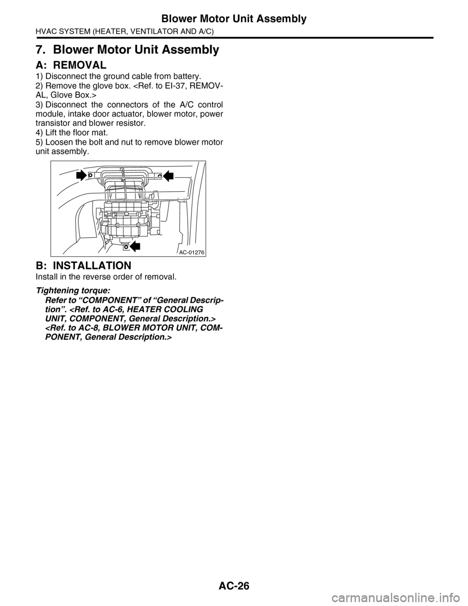
7. Blower Motor Unit Assembly
A: REMOVAL
1) Disconnect the ground cable from battery.
2) Remove the glove box.
3) Disconnect the connectors of the A/C control
module, intake door actuator, blower motor, power
transistor and blower resistor.
4) Lift the floor mat.
5) Loosen the bolt and nut to remove blower motor
unit assembly.
B: INSTALLATION
Install in the reverse order of removal.
Tightening torque:
Refer to “COMPONENT” of “General Descrip-
tion”.
AC-01276
Page 353 of 2453
AC-27
Blower Motor
HVAC SYSTEM (HEATER, VENTILATOR AND A/C)
8. Blower Motor
A: REMOVAL
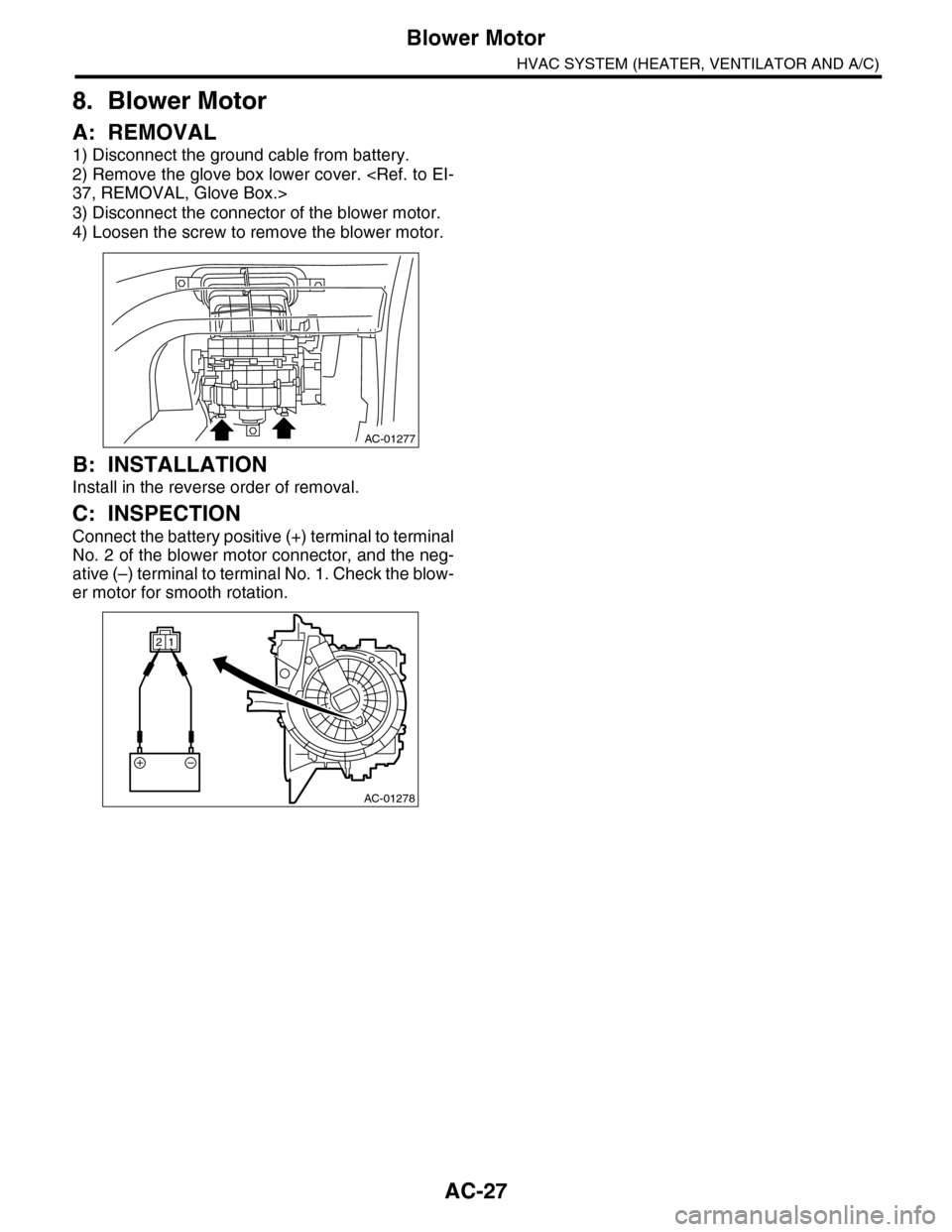
1) Disconnect the ground cable from battery.
2) Remove the glove box lower cover.
3) Disconnect the connector of the blower motor.
4) Loosen the screw to remove the blower motor.
B: INSTALLATION
Install in the reverse order of removal.
C: INSPECTION
Connect the battery positive (+) terminal to terminal
No. 2 of the blower motor connector, and the neg-
ative (–) terminal to terminal No. 1. Check the blow-
er motor for smooth rotation.
AC-01277
AC-01278
12
Page 354 of 2453
AC-28
Power Transistor (Auto A/C Model)
HVAC SYSTEM (HEATER, VENTILATOR AND A/C)
9. Power Transistor (Auto A/C
Model)
A: REMOVAL
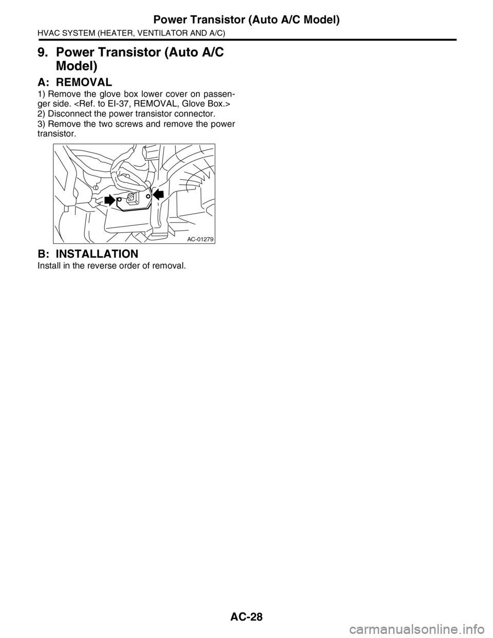
1) Remove the glove box lower cover on passen-
ger side.
2) Disconnect the power transistor connector.
3) Remove the two screws and remove the power
transistor.
B: INSTALLATION
Install in the reverse order of removal.
AC-01279
Page 355 of 2453
AC-29
Blower Resistor (Dual A/C Model)
HVAC SYSTEM (HEATER, VENTILATOR AND A/C)
10.Blower Resistor (Dual A/C
Model)
A: REMOVAL
1) Remove the quarter trim.
2) Disconnect the blower resistor connector.
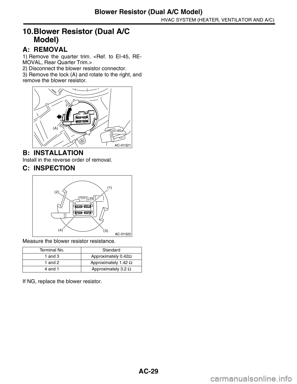
3) Remove the lock (A) and rotate to the right, and
remove the blower resistor.
B: INSTALLATION
Install in the reverse order of removal.
C: INSPECTION
Measure the blower resistor resistance.
If NG, replace the blower resistor.
Te r m i n a l N o . S t a n d a r d
1 and 3 Approximately 0.42Ω
1 and 2 Approximately 1.42 Ω
4 and 1 Approximately 3.2 Ω
AC-01321
(A)
AC-01322(4)(3)
(1)(2)
Page 356 of 2453
AC-30
Heater Core
HVAC SYSTEM (HEATER, VENTILATOR AND A/C)
11.Heater Core
A: REMOVAL
1) Disconnect the ground cable from battery.
2) Draw out the refrigerant with the refrigerant re-
covery unit
3) Remove the heater and cooling unit.
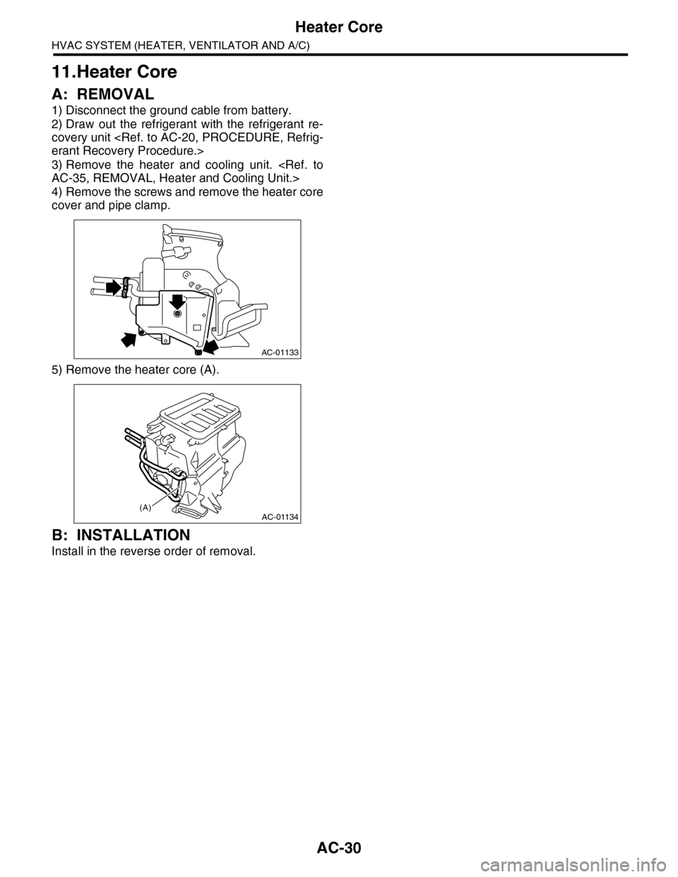
4) Remove the screws and remove the heater core
cover and pipe clamp.
5) Remove the heater core (A).
B: INSTALLATION
Install in the reverse order of removal.
AC-01133
AC-01134(A)
Page 357 of 2453
AC-31
Control Panel
HVAC SYSTEM (HEATER, VENTILATOR AND A/C)
12.Control Panel
A: REMOVAL
1. FRONT
1) Disconnect the ground cable from battery.
2) Remove the front console panel.
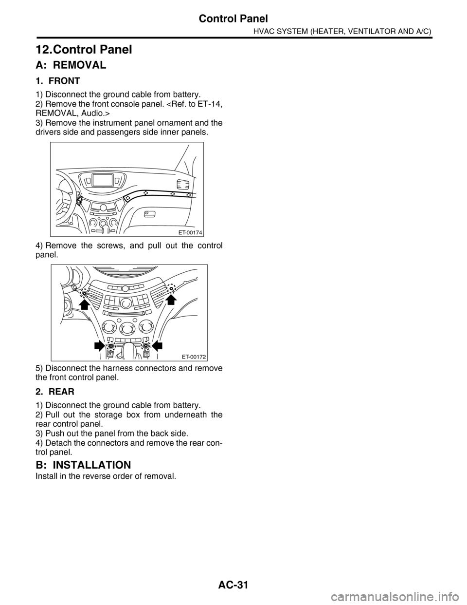
3) Remove the instrument panel ornament and the
drivers side and passengers side inner panels.
4) Remove the screws, and pull out the control
panel.
5) Disconnect the harness connectors and remove
the front control panel.
2. REAR
1) Disconnect the ground cable from battery.
2) Pull out the storage box from underneath the
rear control panel.
3) Push out the panel from the back side.
4) Detach the connectors and remove the rear con-
trol panel.
B: INSTALLATION
Install in the reverse order of removal.
ET-00174
ET-00172
Page 358 of 2453
AC-32
Control Unit (Auto A/C Model)
HVAC SYSTEM (HEATER, VENTILATOR AND A/C)
13.Control Unit (Auto A/C Model)
A: REMOVAL
1) Disconnect the ground cable from battery.
2) Remove the glove box.
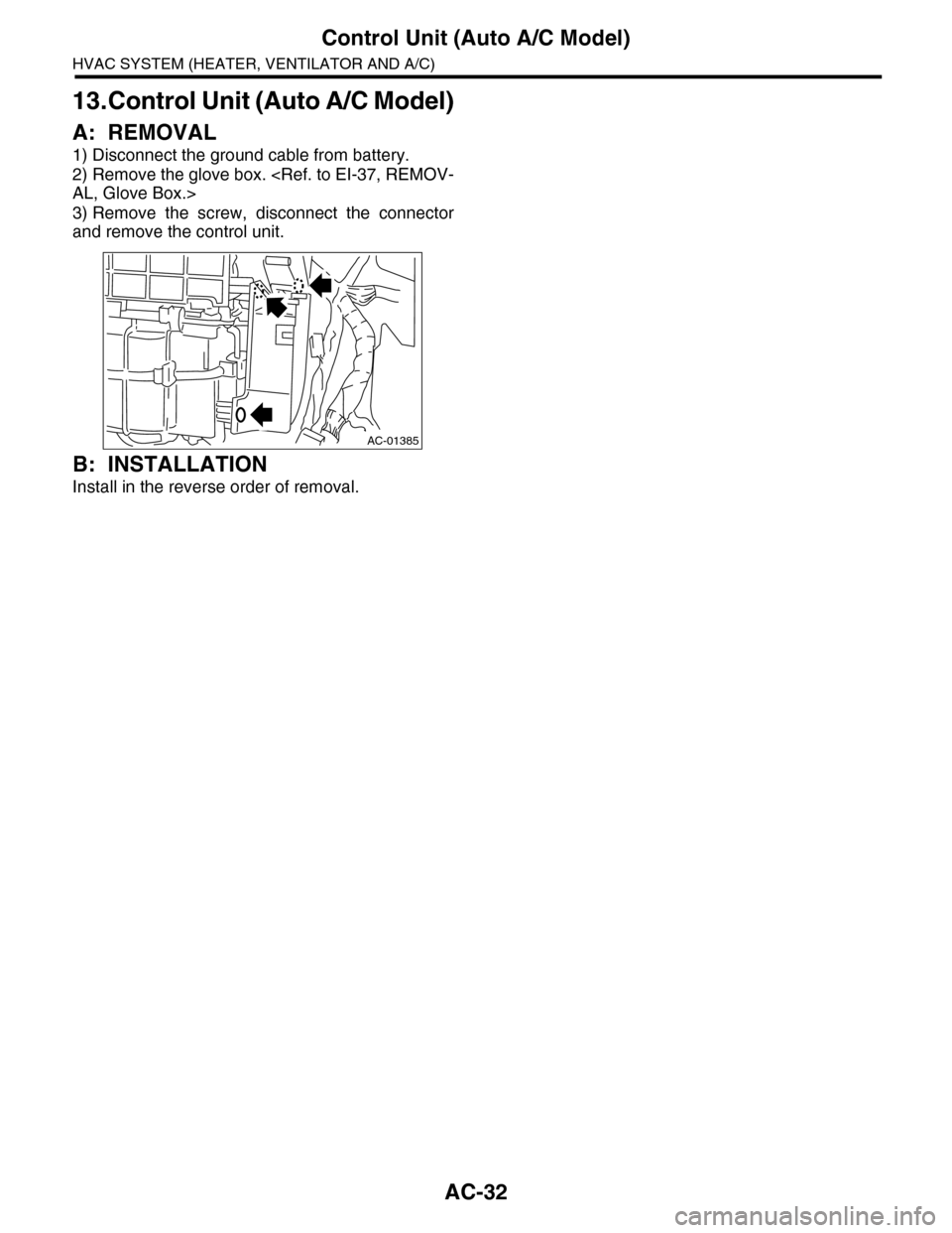
3) Remove the screw, disconnect the connector
and remove the control unit.
B: INSTALLATION
Install in the reverse order of removal.
AC-01385
Page 359 of 2453
AC-33
Compressor
HVAC SYSTEM (HEATER, VENTILATOR AND A/C)
14.Compressor
A: INSPECTION
1. MAGNETIC CLUTCH CLEARANCE
Check the clearance of the entire circumference
around the drive plate and pulley.
Standard:
0.45±0.15 mm (0.0177±0.0059 in)
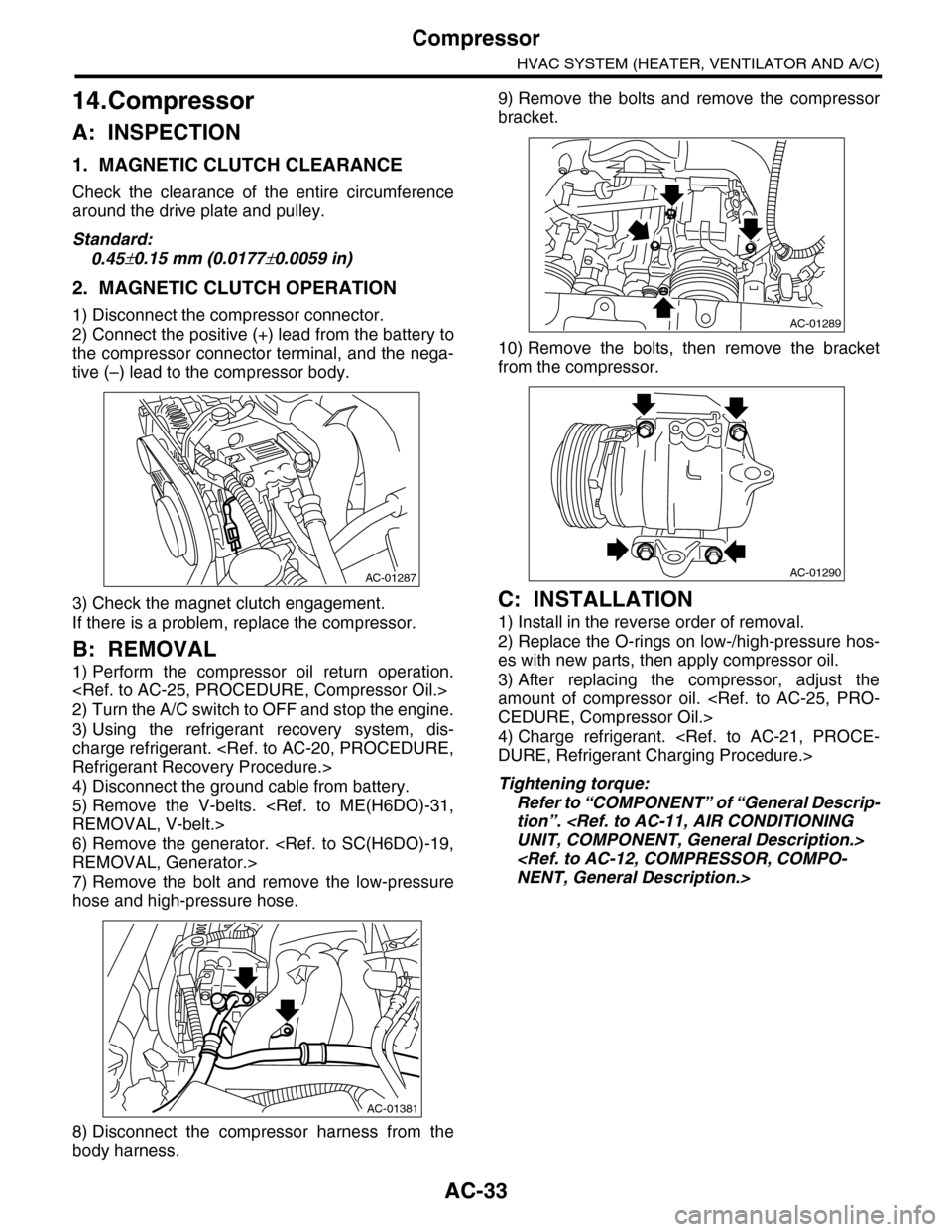
2. MAGNETIC CLUTCH OPERATION
1) Disconnect the compressor connector.
2) Connect the positive (+) lead from the battery to
the compressor connector terminal, and the nega-
tive (–) lead to the compressor body.
3) Check the magnet clutch engagement.
If there is a problem, replace the compressor.
B: REMOVAL
1) Perform the compressor oil return operation.
2) Turn the A/C switch to OFF and stop the engine.
3) Using the refrigerant recovery system, dis-
charge refrigerant.
4) Disconnect the ground cable from battery.
5) Remove the V-belts.
6) Remove the generator.
7) Remove the bolt and remove the low-pressure
hose and high-pressure hose.
8) Disconnect the compressor harness from the
body harness.
9) Remove the bolts and remove the compressor
bracket.
10) Remove the bolts, then remove the bracket
from the compressor.
C: INSTALLATION
1) Install in the reverse order of removal.
2) Replace the O-rings on low-/high-pressure hos-
es with new parts, then apply compressor oil.
3) After replacing the compressor, adjust the
amount of compressor oil.
4) Charge refrigerant.
Tightening torque:
Refer to “COMPONENT” of “General Descrip-
tion”.
AC-01287
AC-01381
AC-01289
AC-01290
Page 360 of 2453
AC-34
Condenser
HVAC SYSTEM (HEATER, VENTILATOR AND A/C)
15.Condenser
A: REMOVAL
1) Using the refrigerant recovery system, dis-
charge refrigerant.
2) Disconnect the ground cable from battery.
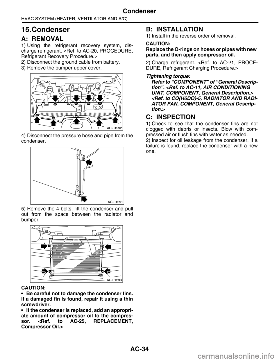
3) Remove the bumper upper cover.
4) Disconnect the pressure hose and pipe from the
condenser.
5) Remove the 4 bolts, lift the condenser and pull
out from the space between the radiator and
bumper.
CAUTION:
•Be careful not to damage the condenser fins.
If a damaged fin is found, repair it using a thin
screwdriver.
•If the condenser is replaced, add an appropri-
ate amount of compressor oil to the compres-
sor.
B: INSTALLATION
1) Install in the reverse order of removal.
CAUTION:
Replace the O-rings on hoses or pipes with new
parts, and then apply compressor oil.
2) Charge refrigerant.
Tightening torque:
Refer to “COMPONENT” of “General Descrip-
tion”.
tion.>
C: INSPECTION
1) Check to see that the condenser fins are not
clogged with debris or insects. Blow with com-
pressed air or flush fins with water as needed.
2) Inspect for oil leakage from the condenser. If a
failure is found, replace the condenser with a new
one.
AC-01292
AC-01291
AC-01293