engine SUBARU TRIBECA 2009 1.G Service Owner's Guide
[x] Cancel search | Manufacturer: SUBARU, Model Year: 2009, Model line: TRIBECA, Model: SUBARU TRIBECA 2009 1.GPages: 2453, PDF Size: 46.32 MB
Page 380 of 2453
AC(diag)-3
General Description
HVAC SYSTEM (AUTO A/C) (DIAGNOSTICS)
2. General Description
A: CAUTION
1) Never connect the battery in reverse polarity.
•Auto A/C control module may be destroyed in-
stantly.
2) Do not disconnect the battery terminals while the
engine is running.
•A large counter electromotive force will be gener-
ated in the generator, and this voltage may damage
electronic parts such as auto A/C control module
etc.
3) Before disconnecting the connectors of each
sensor and the auto A/C control module, be sure to
turn the ignition switch to OFF.
•Auto A/C control module may be damaged.
4) Every A/C-related part is a precision part. Do not
drop them.
5) Airbag system wiring harness is routed near the
A/C control panel and junction box.
CAUTION:
•For airbag system, yellow-colored wiring har-
ness and connectors are all used. Do not use
the electrical test equipment on these circuits.
•Be careful not to damage the airbag system
wiring harness when servicing the A/C control
panel and junction box.
B: INSPECTION
Before performing the diagnosis, check the follow-
ing items which might affect A/C system problems.
1. BATTERY
1) Measure the battery voltage and specific gravity
of electrolyte.
Standard voltage: 12 V
Specific gravity: 1.260 or more
2) Check the condition of the fuses for A/C system
power supply and other fuses.
3) Check the condition of harness and harness
connector connections.
2. ASPIRATOR HOSE
1) Turn the ignition switch to ON, and press the A/
C switch.
2) Turn the temperature control dial to maximum
hot position.
3) Turn the air flow control dial to “DEF” position.
4) Turn the fan speed control dial to 4th position.
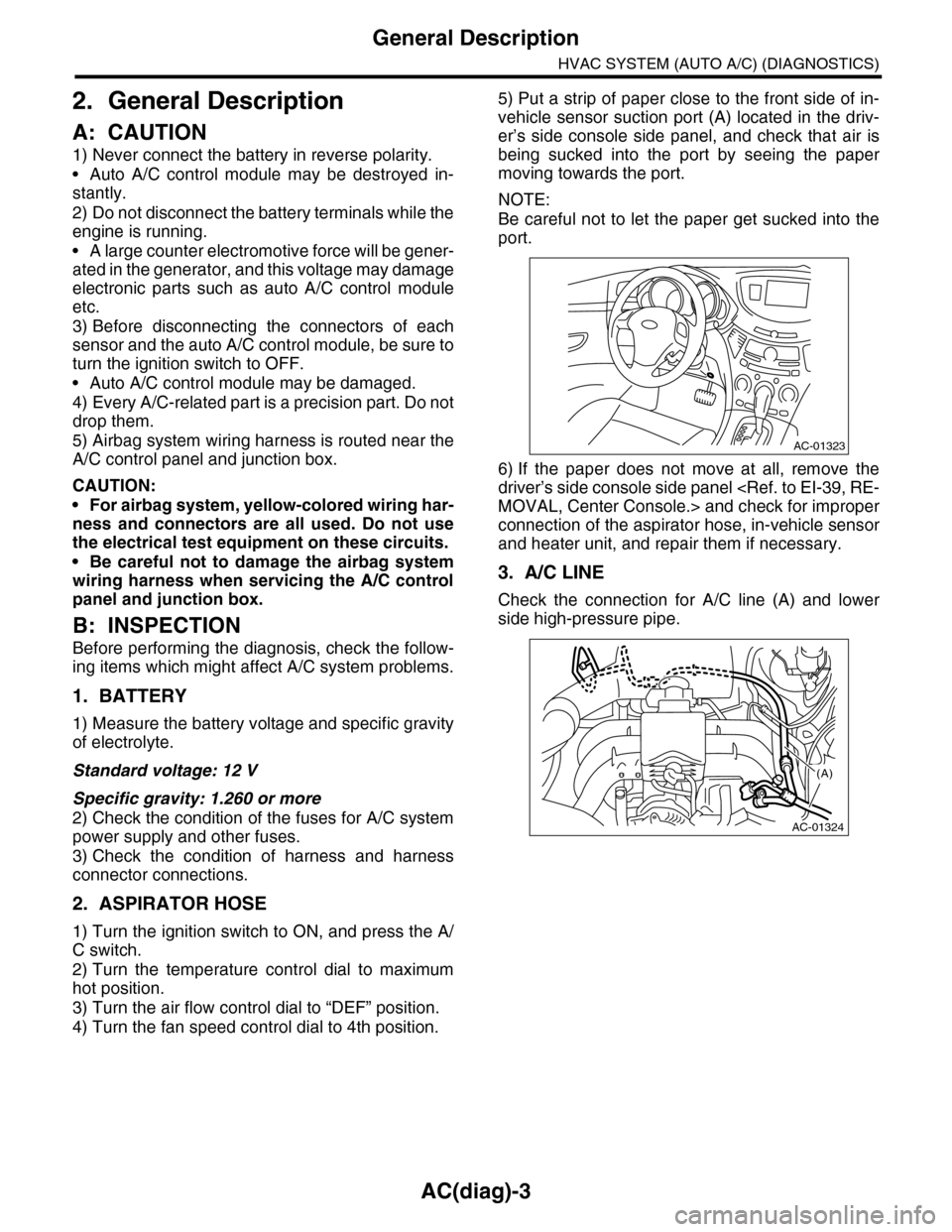
5) Put a strip of paper close to the front side of in-
vehicle sensor suction port (A) located in the driv-
er’s side console side panel, and check that air is
being sucked into the port by seeing the paper
moving towards the port.
NOTE:
Be careful not to let the paper get sucked into the
port.
6) If the paper does not move at all, remove the
driver’s side console side panel
connection of the aspirator hose, in-vehicle sensor
and heater unit, and repair them if necessary.
3. A/C LINE
Check the connection for A/C line (A) and lower
side high-pressure pipe.
AC-01323
AC-01324
(A)
Page 381 of 2453
AC(diag)-4
General Description
HVAC SYSTEM (AUTO A/C) (DIAGNOSTICS)
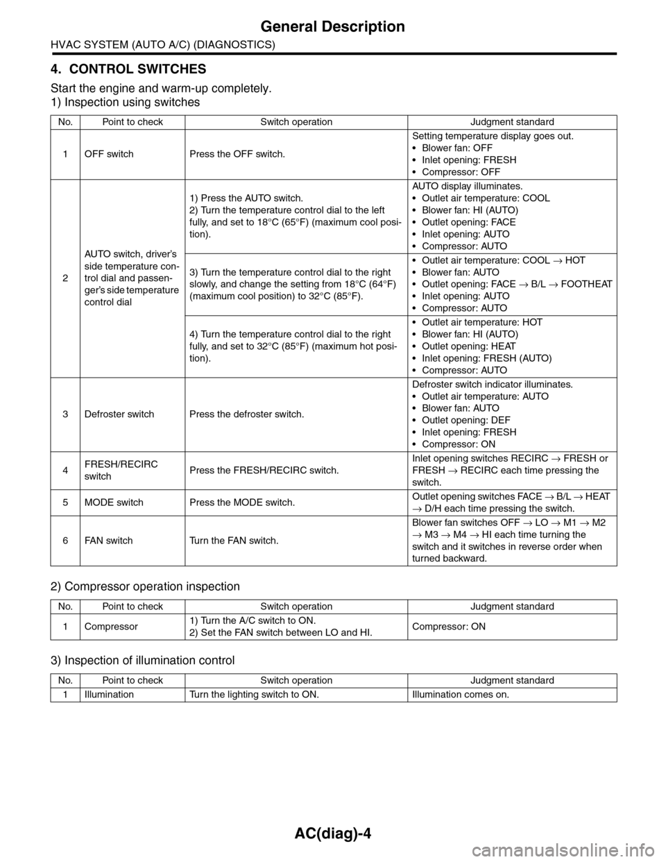
4. CONTROL SWITCHES
Start the engine and warm-up completely.
1) Inspection using switches
2) Compressor operation inspection
3) Inspection of illumination control
No. Point to check Switch operation Judgment standard
1OFF switch Press the OFF switch.
Setting temperature display goes out.
•Blower fan: OFF
•Inlet opening: FRESH
•Compressor: OFF
2
AU TO sw it c h, d r iver ’s
side temperature con-
trol dial and passen-
ger’s side temperature
control dial
1) Press the AUTO switch.
2) Turn the temperature control dial to the left
fully, and set to 18°C (65°F) (maximum cool posi-
tion).
AU TO di sp l ay i l lu mi n at e s.
•Outlet air temperature: COOL
•Blower fan: HI (AUTO)
•Outlet opening: FACE
•Inlet opening: AUTO
•Compressor: AUTO
3) Turn the temperature control dial to the right
slowly, and change the setting from 18°C (64°F)
(maximum cool position) to 32°C (85°F).
•Outlet air temperature: COOL → HOT
•Blower fan: AUTO
•Outlet opening: FACE → B/L → FOOTHEAT
•Inlet opening: AUTO
•Compressor: AUTO
4) Turn the temperature control dial to the right
fully, and set to 32°C (85°F) (maximum hot posi-
tion).
•Outlet air temperature: HOT
•Blower fan: HI (AUTO)
•Outlet opening: HEAT
•Inlet opening: FRESH (AUTO)
•Compressor: AUTO
3Defroster switch Press the defroster switch.
Defroster switch indicator illuminates.
•Outlet air temperature: AUTO
•Blower fan: AUTO
•Outlet opening: DEF
•Inlet opening: FRESH
•Compressor: ON
4FRESH/RECIRC
switchPress the FRESH/RECIRC switch.
Inlet opening switches RECIRC → FRESH or
FRESH → RECIRC each time pressing the
switch.
5MODE switch Press the MODE switch.Outlet opening switches FACE → B / L → HEAT
→ D/H each time pressing the switch.
6FAN switch Turn the FAN switch.
Blower fan switches OFF → LO → M1 → M2
→ M3 → M4 → HI each time turning the
switch and it switches in reverse order when
turned backward.
No. Point to check Switch operation Judgment standard
1Compressor1) Turn the A/C switch to ON.
2) Set the FAN switch between LO and HI.Compressor: ON
No. Point to check Switch operation Judgment standard
1Illumination Turn the lighting switch to ON. Illumination comes on.
Page 383 of 2453
AC(diag)-6
Electrical Component Location
HVAC SYSTEM (AUTO A/C) (DIAGNOSTICS)
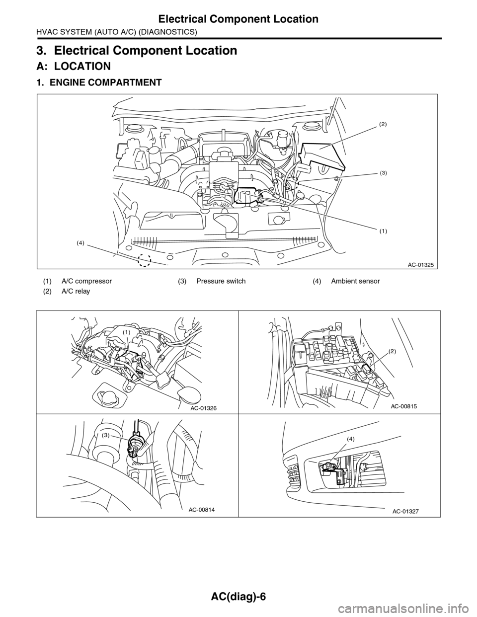
3. Electrical Component Location
A: LOCATION
1. ENGINE COMPARTMENT
(1) A/C compressor (3) Pressure switch (4) Ambient sensor
(2) A/C relay
AC-01325
(4)
(2)
(3)
(1)
AC-01326
(1)
AC-00815
(2)
AC-00814
(3)
AC-01327
(4)
Page 390 of 2453
AC(diag)-13
Diagnostic Chart for Self-diagnosis
HVAC SYSTEM (AUTO A/C) (DIAGNOSTICS)
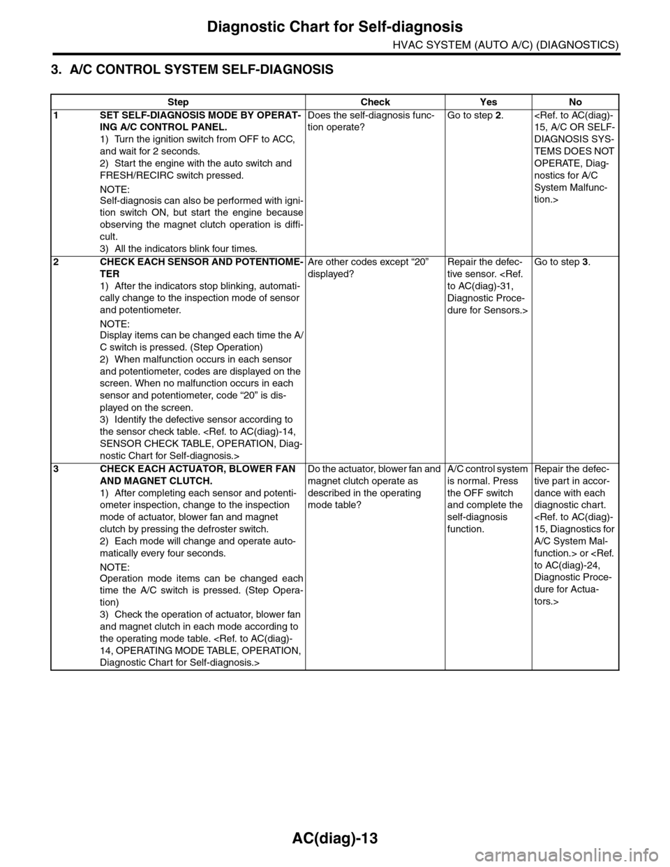
3. A/C CONTROL SYSTEM SELF-DIAGNOSIS
Step Check Yes No
1SET SELF-DIAGNOSIS MODE BY OPERAT-
ING A/C CONTROL PANEL.
1) Turn the ignition switch from OFF to ACC,
and wait for 2 seconds.
2) Start the engine with the auto switch and
FRESH/RECIRC switch pressed.
NOTE:
Self-diagnosis can also be performed with igni-
tion switch ON, but start the engine because
observing the magnet clutch operation is diffi-
cult.
3) All the indicators blink four times.
Does the self-diagnosis func-
tion operate?
Go to step 2.
DIAGNOSIS SYS-
TEMS DOES NOT
OPERATE, Diag-
nostics for A/C
System Malfunc-
tion.>
2CHECK EACH SENSOR AND POTENTIOME-
TER
1) After the indicators stop blinking, automati-
cally change to the inspection mode of sensor
and potentiometer.
NOTE:
Display items can be changed each time the A/
C switch is pressed. (Step Operation)
2) When malfunction occurs in each sensor
and potentiometer, codes are displayed on the
screen. When no malfunction occurs in each
sensor and potentiometer, code “20” is dis-
played on the screen.
3) Identify the defective sensor according to
the sensor check table.
nostic Chart for Self-diagnosis.>
Are other codes except “20”
displayed?
Repair the defec-
tive sensor.
Diagnostic Proce-
dure for Sensors.>
Go to step 3.
3CHECK EACH ACTUATOR, BLOWER FAN
AND MAGNET CLUTCH.
1) After completing each sensor and potenti-
ometer inspection, change to the inspection
mode of actuator, blower fan and magnet
clutch by pressing the defroster switch.
2) Each mode will change and operate auto-
matically every four seconds.
NOTE:
Operation mode items can be changed each
time the A/C switch is pressed. (Step Opera-
tion)
3) Check the operation of actuator, blower fan
and magnet clutch in each mode according to
the operating mode table.
Diagnostic Chart for Self-diagnosis.>
Do the actuator, blower fan and
magnet clutch operate as
described in the operating
mode table?
A/C control system
is normal. Press
the OFF switch
and complete the
self-diagnosis
function.
Repair the defec-
tive par t in accor-
dance with each
diagnostic chart.
A/C System Mal-
function.> or
Diagnostic Proce-
dure for Actua-
tors.>
Page 391 of 2453
AC(diag)-14
Diagnostic Chart for Self-diagnosis
HVAC SYSTEM (AUTO A/C) (DIAGNOSTICS)
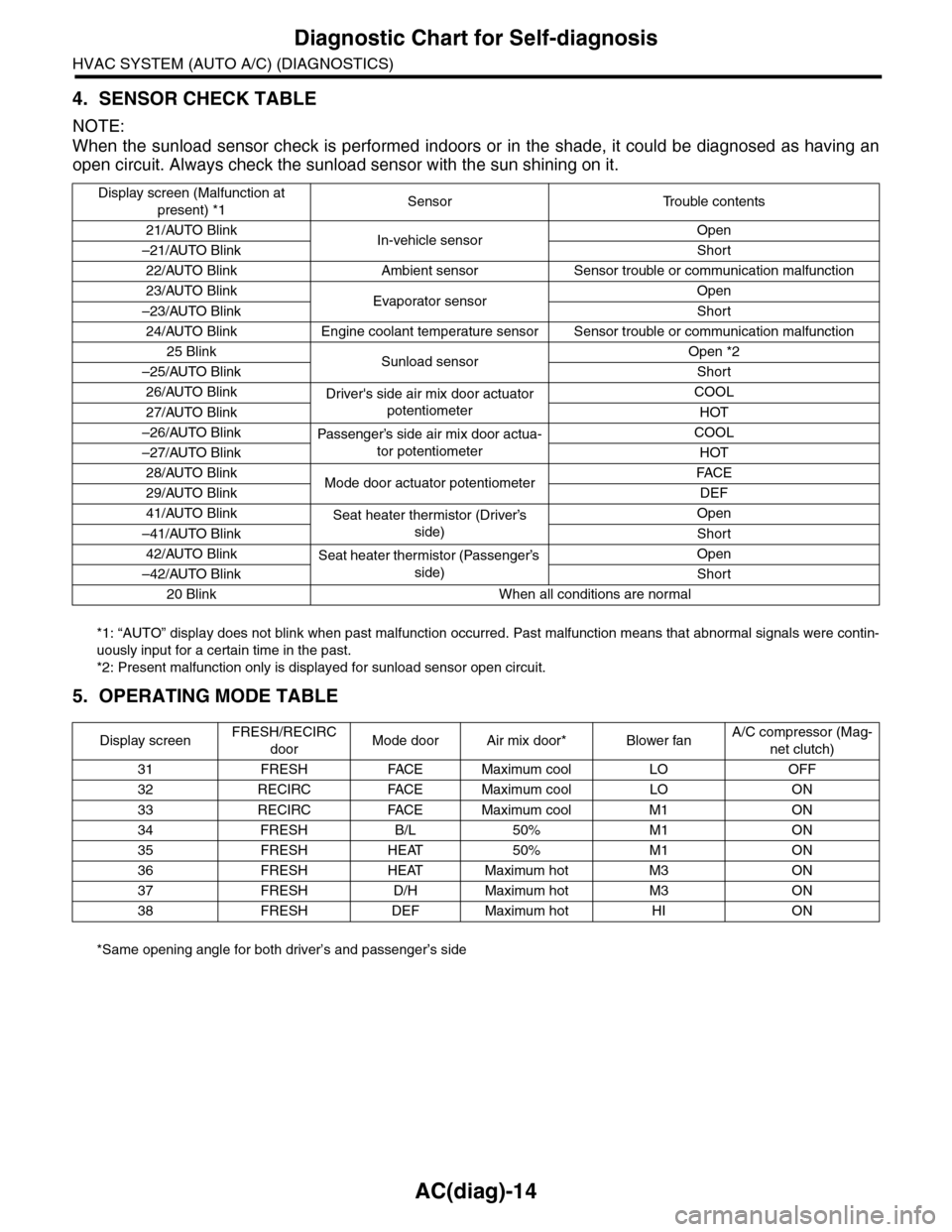
4. SENSOR CHECK TABLE
NOTE:
When the sunload sensor check is performed indoors or in the shade, it could be diagnosed as having an
open circuit. Always check the sunload sensor with the sun shining on it.
*1: “AUTO” display does not blink when past malfunction occurred. Past malfunction means that abnormal signals were contin-
uously input for a certain time in the past.
*2: Present malfunction only is displayed for sunload sensor open circuit.
5. OPERATING MODE TABLE
*Same opening angle for both driver’s and passenger’s side
Display screen (Malfunction at
present) *1Sensor Trouble contents
21/AUTO BlinkIn-vehicle sensorOpen
–21/AUTO BlinkShort
22/AUTO Blink Ambient sensor Sensor trouble or communication malfunction
23/AUTO BlinkEvaporator sensorOpen
–23/AUTO BlinkShort
24/AUTO Blink Engine coolant temperature sensor Sensor trouble or communication malfunction
25 BlinkSunload sensorOpen *2
–25/AUTO BlinkShort
26/AUTO BlinkDriver's side air mix door actuator
potentiometer
COOL
27/AUTO BlinkHOT
–26/AUTO BlinkPassenger’s side air mix door actua-
tor potentiometer
COOL
–27/AUTO BlinkHOT
28/AUTO BlinkMode door actuator potentiometerFA C E
29/AUTO BlinkDEF
41/AUTO BlinkSeat heater thermistor (Driver’s
side)
Open
–41/AUTO BlinkShort
42/AUTO BlinkSeat heater thermistor (Passenger’s
side)
Open
–42/AUTO BlinkShort
20 Blink When all conditions are normal
Display screenFRESH/RECIRC
doorMode door Air mix door* Blower fanA/C compressor (Mag-
net clutch)
31 FRESH FACE Maximum cool LO OFF
32 RECIRC FACE Maximum cool LO ON
33 RECIRC FACE Maximum cool M1 ON
34 FRESH B/L 50% M1 ON
35 FRESH HEAT 50% M1 ON
36 FRESH HEAT Maximum hot M3 ON
37 FRESH D/H Maximum hot M3 ON
38 FRESH DEF Maximum hot HI ON
Page 399 of 2453
AC(diag)-22
Diagnostics for A/C System Malfunction
HVAC SYSTEM (AUTO A/C) (DIAGNOSTICS)
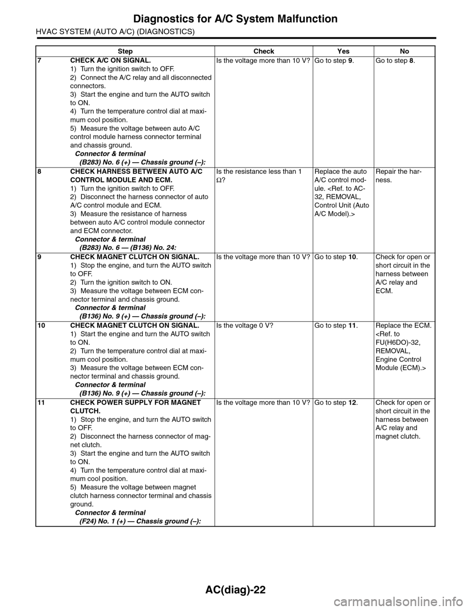
7CHECK A/C ON SIGNAL.
1) Turn the ignition switch to OFF.
2) Connect the A/C relay and all disconnected
connectors.
3) Start the engine and turn the AUTO switch
to ON.
4) Turn the temperature control dial at maxi-
mum cool position.
5) Measure the voltage between auto A/C
control module harness connector terminal
and chassis ground.
Connector & terminal
(B283) No. 6 (+) — Chassis ground (–):
Is the voltage more than 10 V? Go to step 9.Go to step 8.
8CHECK HARNESS BETWEEN AUTO A/C
CONTROL MODULE AND ECM.
1) Turn the ignition switch to OFF.
2) Disconnect the harness connector of auto
A/C control module and ECM.
3) Measure the resistance of harness
between auto A/C control module connector
and ECM connector.
Connector & terminal
(B283) No. 6 — (B136) No. 24:
Is the resistance less than 1
Ω?
Replace the auto
A/C control mod-
ule.
Control Unit (Auto
A/C Model).>
Repair the har-
ness.
9CHECK MAGNET CLUTCH ON SIGNAL.
1) Stop the engine, and turn the AUTO switch
to OFF.
2) Turn the ignition switch to ON.
3) Measure the voltage between ECM con-
nector terminal and chassis ground.
Connector & terminal
(B136) No. 9 (+) — Chassis ground (–):
Is the voltage more than 10 V? Go to step 10.Check for open or
short circuit in the
harness between
A/C relay and
ECM.
10 CHECK MAGNET CLUTCH ON SIGNAL.
1) Start the engine and turn the AUTO switch
to ON.
2) Turn the temperature control dial at maxi-
mum cool position.
3) Measure the voltage between ECM con-
nector terminal and chassis ground.
Connector & terminal
(B136) No. 9 (+) — Chassis ground (–):
Is the voltage 0 V? Go to step 11.Replace the ECM.
REMOVAL,
Engine Control
Module (ECM).>
11 CHECK POWER SUPPLY FOR MAGNET
CLUTCH.
1) Stop the engine, and turn the AUTO switch
to OFF.
2) Disconnect the harness connector of mag-
net clutch.
3) Start the engine and turn the AUTO switch
to ON.
4) Turn the temperature control dial at maxi-
mum cool position.
5) Measure the voltage between magnet
clutch harness connector terminal and chassis
ground.
Connector & terminal
(F24) No. 1 (+) — Chassis ground (–):
Is the voltage more than 10 V? Go to step 12.Check for open or
short circuit in the
harness between
A/C relay and
magnet clutch.
Step Check Yes No
Page 400 of 2453
AC(diag)-23
Diagnostics for A/C System Malfunction
HVAC SYSTEM (AUTO A/C) (DIAGNOSTICS)
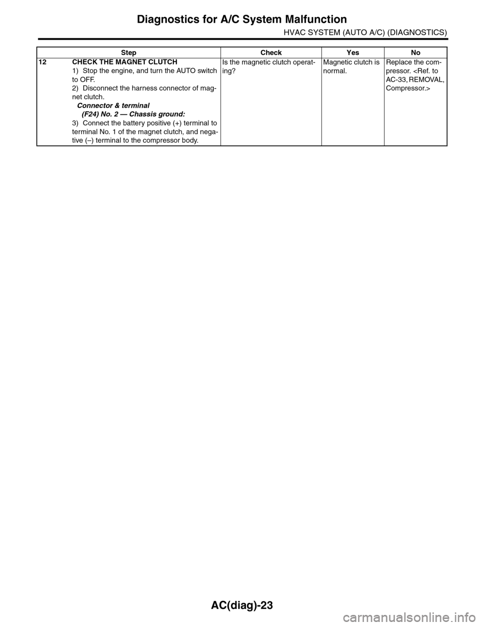
12 CHECK THE MAGNET CLUTCH
1) Stop the engine, and turn the AUTO switch
to OFF.
2) Disconnect the harness connector of mag-
net clutch.
Connector & terminal
(F24) No. 2 — Chassis ground:
3) Connect the battery positive (+) terminal to
terminal No. 1 of the magnet clutch, and nega-
tive (–) terminal to the compressor body.
Is the magnetic clutch operat-
ing?
Magnetic clutch is
normal.
Replace the com-
pressor.
Compressor.>
Step Check Yes No
Page 418 of 2453
IM (diag)-2
Basic Diagnostic Procedure
IMMOBILIZER (DIAGNOSTICS)
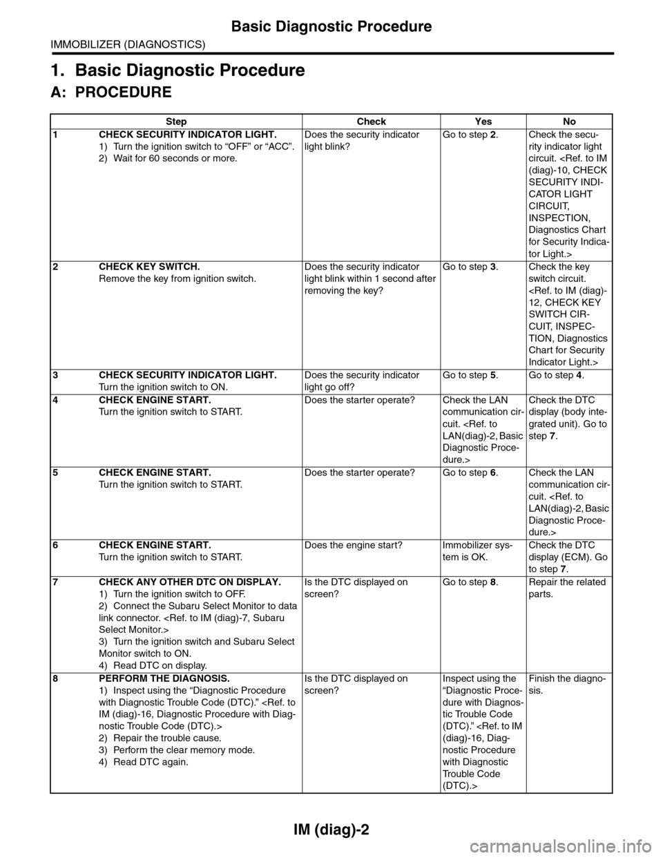
1. Basic Diagnostic Procedure
A: PROCEDURE
Step Check Yes No
1CHECK SECURITY INDICATOR LIGHT.
1) Turn the ignition switch to “OFF” or “ACC”.
2) Wait for 60 seconds or more.
Does the security indicator
light blink?
Go to step 2.Check the secu-
rity indicator light
circuit.
SECURITY INDI-
CATOR LIGHT
CIRCUIT,
INSPECTION,
Diagnostics Chart
for Secur ity Indica-
tor Light.>
2CHECK KEY SWITCH.
Remove the key from ignition switch.
Does the security indicator
light blink within 1 second after
removing the key?
Go to step 3.Check the key
switch circuit.
SWITCH CIR-
CUIT, INSPEC-
TION, Diagnostics
Chart for Security
Indicator Light.>
3CHECK SECURITY INDICATOR LIGHT.
Tu r n t h e i g n i t i o n s w i t c h t o O N .
Does the security indicator
light go off?
Go to step 5.Go to step 4.
4CHECK ENGINE START.
Tu r n t h e i g n i t i o n s w i t c h t o S TA R T.
Does the starter operate? Check the LAN
communication cir-
cuit.
Diagnostic Proce-
dure.>
Check the DTC
display (body inte-
grated unit). Go to
step 7.
5CHECK ENGINE START.
Tu r n t h e i g n i t i o n s w i t c h t o S TA R T.
Does the starter operate? Go to step 6.Check the LAN
communication cir-
cuit.
Diagnostic Proce-
dure.>
6CHECK ENGINE START.
Tu r n t h e i g n i t i o n s w i t c h t o S TA R T.
Does the engine start? Immobilizer sys-
tem is OK.
Check the DTC
display (ECM). Go
to step 7.
7CHECK ANY OTHER DTC ON DISPLAY.
1) Turn the ignition switch to OFF.
2) Connect the Subaru Select Monitor to data
link connector.
3) Turn the ignition switch and Subaru Select
Monitor switch to ON.
4) Read DTC on display.
Is the DTC displayed on
screen?
Go to step 8.Repair the related
parts.
8PERFORM THE DIAGNOSIS.
1) Inspect using the “Diagnostic Procedure
with Diagnostic Trouble Code (DTC).”
nostic Trouble Code (DTC).>
2) Repair the trouble cause.
3) Perform the clear memory mode.
4) Read DTC again.
Is the DTC displayed on
screen?
Inspect using the
“Diagnostic Proce-
dure with Diagnos-
tic Trouble Code
(DTC).”
nostic Procedure
with Diagnostic
Tr o u b l e C o d e
(DTC).>
Finish the diagno-
sis.
Page 419 of 2453
IM (diag)-3
General Description
IMMOBILIZER (DIAGNOSTICS)
2. General Description
A: CAUTION
CAUTION:
•The airbag system wiring harnesses and con-
nectors are yellow. Do not use electrical test
equipment on these circuits.
•Be careful not to damage the airbag system
wiring harness.
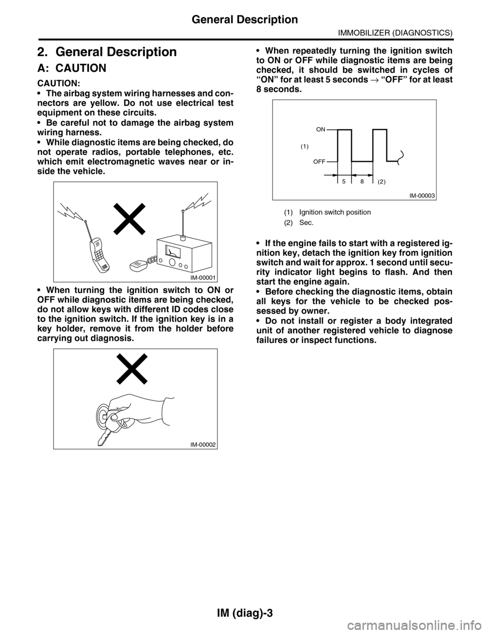
•While diagnostic items are being checked, do
not operate radios, portable telephones, etc.
which emit electromagnetic waves near or in-
side the vehicle.
•When turning the ignition switch to ON or
OFF while diagnostic items are being checked,
do not allow keys with different ID codes close
to the ignition switch. If the ignition key is in a
key holder, remove it from the holder before
carrying out diagnosis.
•When repeatedly turning the ignition switch
to ON or OFF while diagnostic items are being
checked, it should be switched in cycles of
“ON” for at least 5 seconds → “O F F ” fo r a t le a s t
8 seconds.
•If the engine fails to start with a registered ig-
nition key, detach the ignition key from ignition
switch and wait for approx. 1 second until secu-
rity indicator light begins to flash. And then
start the engine again.
•Before checking the diagnostic items, obtain
all keys for the vehicle to be checked pos-
sessed by owner.
•Do not install or register a body integrated
unit of another registered vehicle to diagnose
failures or inspect functions.
IM-00001
IM-00002
(1) Ignition switch position
(2) Sec.
IM-00003
ON
OFF
58(2)
(1)
Page 423 of 2453
IM (diag)-7
Subaru Select Monitor
IMMOBILIZER (DIAGNOSTICS)
5. Subaru Select Monitor
A: OPERATION
1. HOW TO USE SUBARU SELECT MONI-
TOR
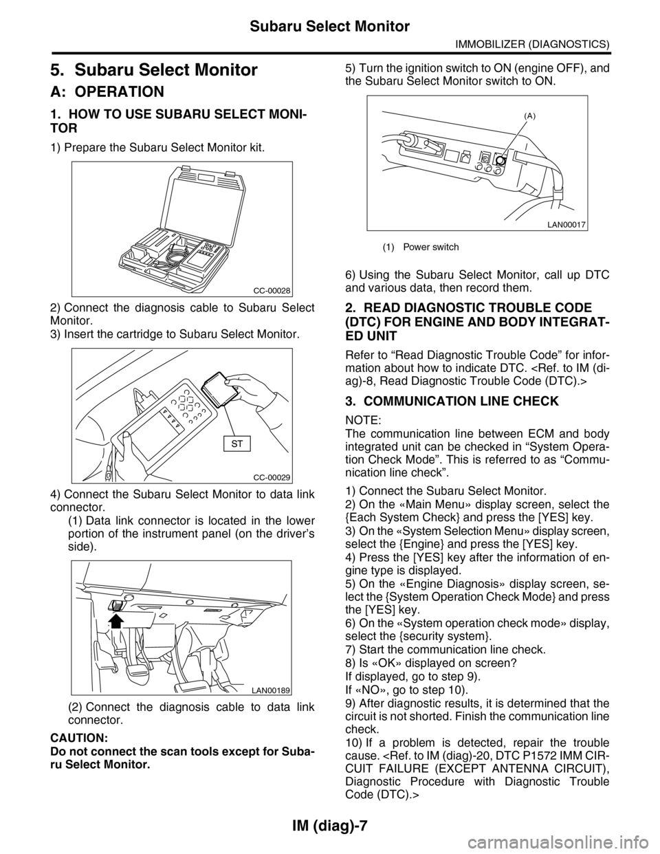
1) Prepare the Subaru Select Monitor kit.
2) Connect the diagnosis cable to Subaru Select
Monitor.
3) Insert the cartridge to Subaru Select Monitor.
4) Connect the Subaru Select Monitor to data link
connector.
(1) Data link connector is located in the lower
portion of the instrument panel (on the driver’s
side).
(2) Connect the diagnosis cable to data link
connector.
CAUTION:
Do not connect the scan tools except for Suba-
ru Select Monitor.
5) Turn the ignition switch to ON (engine OFF), and
the Subaru Select Monitor switch to ON.
6) Using the Subaru Select Monitor, call up DTC
and various data, then record them.
2. READ DIAGNOSTIC TROUBLE CODE
(DTC) FOR ENGINE AND BODY INTEGRAT-
ED UNIT
Refer to “Read Diagnostic Trouble Code” for infor-
mation about how to indicate DTC.
3. COMMUNICATION LINE CHECK
NOTE:
The communication line between ECM and body
integrated unit can be checked in “System Opera-
tion Check Mode”. This is referred to as “Commu-
nication line check”.
1) Connect the Subaru Select Monitor.
2) On the «Main Menu» display screen, select the
{Each System Check} and press the [YES] key.
3) On the «System Selection Menu» display screen,
select the {Engine} and press the [YES] key.
4) Press the [YES] key after the information of en-
gine type is displayed.
5) On the «Engine Diagnosis» display screen, se-
lect the {System Operation Check Mode} and press
the [YES] key.
6) On the «System operation check mode» display,
select the {security system}.
7) Start the communication line check.
8) Is «OK» displayed on screen?
If displayed, go to step 9).
If «NO», go to step 10).
9) After diagnostic results, it is determined that the
circuit is not shorted. Finish the communication line
check.
10) If a problem is detected, repair the trouble
cause.
Diagnostic Procedure with Diagnostic Trouble
Code (DTC).>
CC-00028
CC-00029
LAN00189
(1) Power switch
LAN00017
(A)