SUBARU TRIBECA 2009 1.G Service Workshop Manual
Manufacturer: SUBARU, Model Year: 2009, Model line: TRIBECA, Model: SUBARU TRIBECA 2009 1.GPages: 2453, PDF Size: 46.32 MB
Page 561 of 2453
LI-28
High-mounted Stop Light
LIGHTING SYSTEM
26.High-mounted Stop Light
A: REMOVAL
1) Disconnect the ground cable from battery.
2) Detach the roof spoiler.
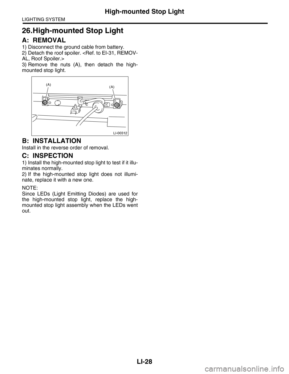
3) Remove the nuts (A), then detach the high-
mounted stop light.
B: INSTALLATION
Install in the reverse order of removal.
C: INSPECTION
1) Install the high-mounted stop light to test if it illu-
minates normally.
2) If the high-mounted stop light does not illumi-
nate, replace it with a new one.
NOTE:
Since LEDs (Light Emitting Diodes) are used for
the high-mounted stop light, replace the high-
mounted stop light assembly when the LEDs went
out.
LI-00312
(A)(A)
Page 562 of 2453
LI-29
Spot Map Light
LIGHTING SYSTEM
27.Spot Map Light
A: REMOVAL
1) Disconnect the ground cable from battery.
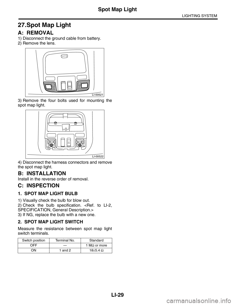
2) Remove the lens.
3) Remove the four bolts used for mounting the
spot map light.
4) Disconnect the harness connectors and remove
the spot map light.
B: INSTALLATION
Install in the reverse order of removal.
C: INSPECTION
1. SPOT MAP LIGHT BULB
1) Visually check the bulb for blow out.
2) Check the bulb specification.
3) If NG, replace the bulb with a new one.
2. SPOT MAP LIGHT SWITCH
Measure the resistance between spot map light
switch terminals.
Switch position Terminal No. Standard
OFF — 1 MΩ or more
ON 1 and 2 18±5.4 Ω
LI-00521
LI-00522
Page 563 of 2453
LI-30
Room Light
LIGHTING SYSTEM
28.Room Light
A: REMOVAL
1. MODEL WITHOUT REAR ENTERTAIN-
MENT SYSTEM
1) Disconnect the ground cable from battery.
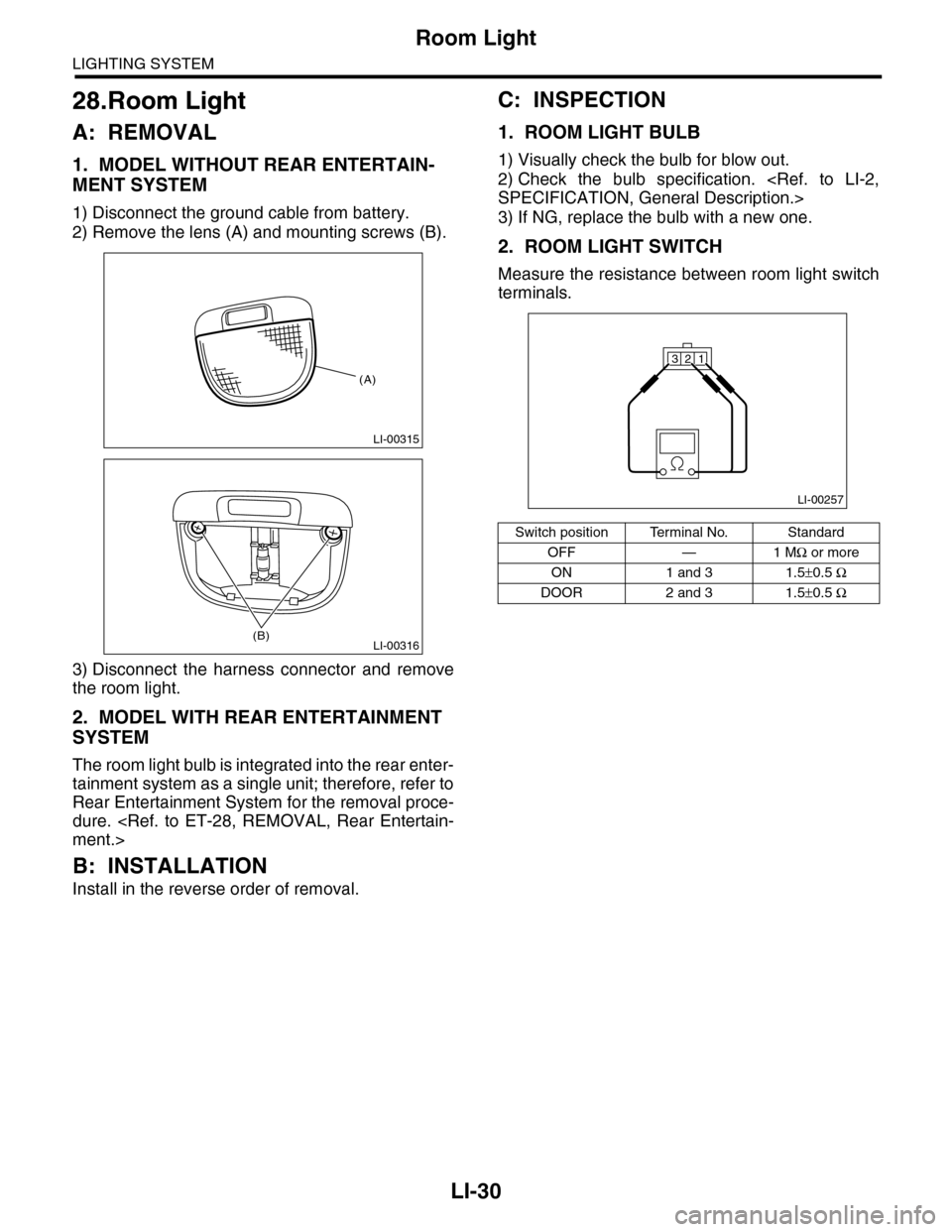
2) Remove the lens (A) and mounting screws (B).
3) Disconnect the harness connector and remove
the room light.
2. MODEL WITH REAR ENTERTAINMENT
SYSTEM
The room light bulb is integrated into the rear enter-
tainment system as a single unit; therefore, refer to
Rear Entertainment System for the removal proce-
dure.
B: INSTALLATION
Install in the reverse order of removal.
C: INSPECTION
1. ROOM LIGHT BULB
1) Visually check the bulb for blow out.
2) Check the bulb specification.
3) If NG, replace the bulb with a new one.
2. ROOM LIGHT SWITCH
Measure the resistance between room light switch
terminals.
LI-00315
(A)
LI-00316(B)
Switch position Terminal No. Standard
OFF — 1 MΩ or more
ON 1 and 3 1.5±0.5 Ω
DOOR 2 and 3 1.5±0.5 Ω
LI-00257
321
Page 564 of 2453
LI-31
Luggage Room Light
LIGHTING SYSTEM
29.Luggage Room Light
A: REMOVAL
1) Disconnect the ground cable from battery.
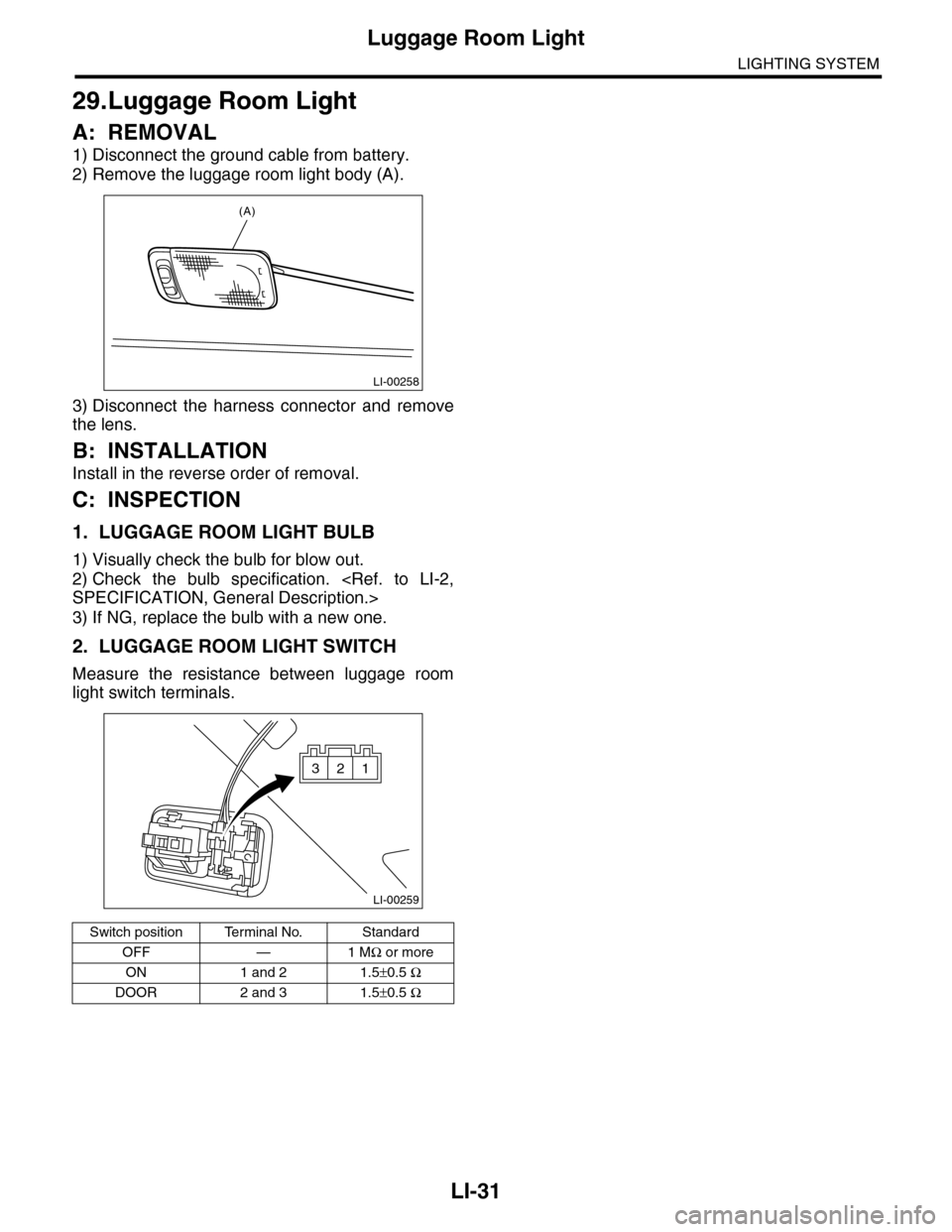
2) Remove the luggage room light body (A).
3) Disconnect the harness connector and remove
the lens.
B: INSTALLATION
Install in the reverse order of removal.
C: INSPECTION
1. LUGGAGE ROOM LIGHT BULB
1) Visually check the bulb for blow out.
2) Check the bulb specification.
3) If NG, replace the bulb with a new one.
2. LUGGAGE ROOM LIGHT SWITCH
Measure the resistance between luggage room
light switch terminals.
Switch position Terminal No. Standard
OFF — 1 MΩ or more
ON 1 and 2 1.5±0.5 Ω
DOOR 2 and 3 1.5±0.5 Ω
LI-00258
(A)
LI-00259
321
Page 565 of 2453
LI-32
Rear Gate Light
LIGHTING SYSTEM
30.Rear Gate Light
A: REMOVAL
1) Disconnect the ground cable from battery.
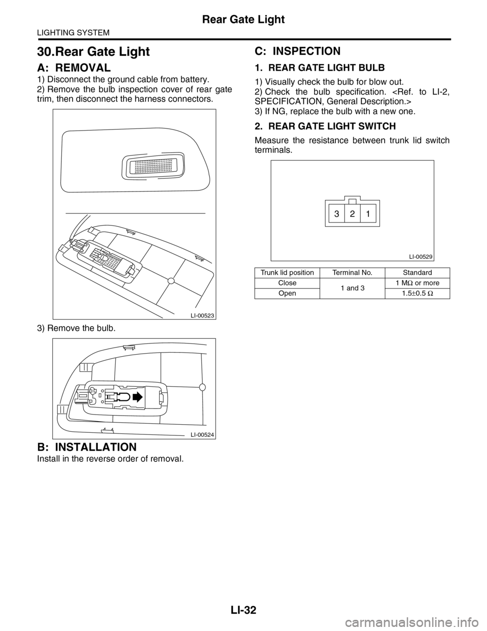
2) Remove the bulb inspection cover of rear gate
trim, then disconnect the harness connectors.
3) Remove the bulb.
B: INSTALLATION
Install in the reverse order of removal.
C: INSPECTION
1. REAR GATE LIGHT BULB
1) Visually check the bulb for blow out.
2) Check the bulb specification.
3) If NG, replace the bulb with a new one.
2. REAR GATE LIGHT SWITCH
Measure the resistance between trunk lid switch
terminals.
LI-00523
LI-00524
Tr u n k l i d p o s i t i o n Te r m i n a l N o . S t a n d a r d
Close1 and 31 MΩ or more
Open 1.5±0.5 Ω
LI-00529
321
Page 566 of 2453
LI-33
Glove Box Light
LIGHTING SYSTEM
31.Glove Box Light
A: REMOVAL
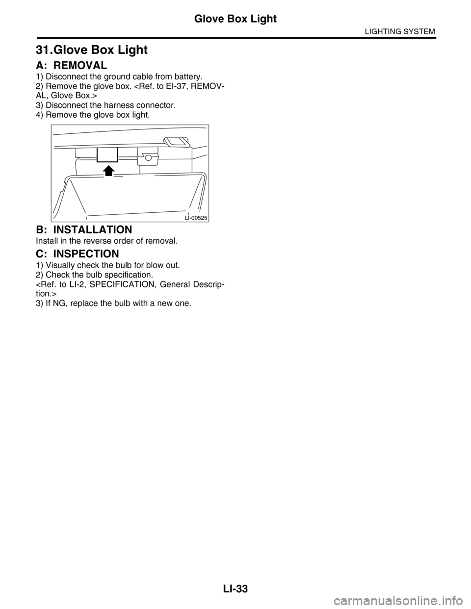
1) Disconnect the ground cable from battery.
2) Remove the glove box.
3) Disconnect the harness connector.
4) Remove the glove box light.
B: INSTALLATION
Install in the reverse order of removal.
C: INSPECTION
1) Visually check the bulb for blow out.
2) Check the bulb specification.
3) If NG, replace the bulb with a new one.
LI-00525
Page 567 of 2453
LI-34
Door Step Light
LIGHTING SYSTEM
32.Door Step Light
A: REMOVAL
1) Disconnect the ground cable from battery.
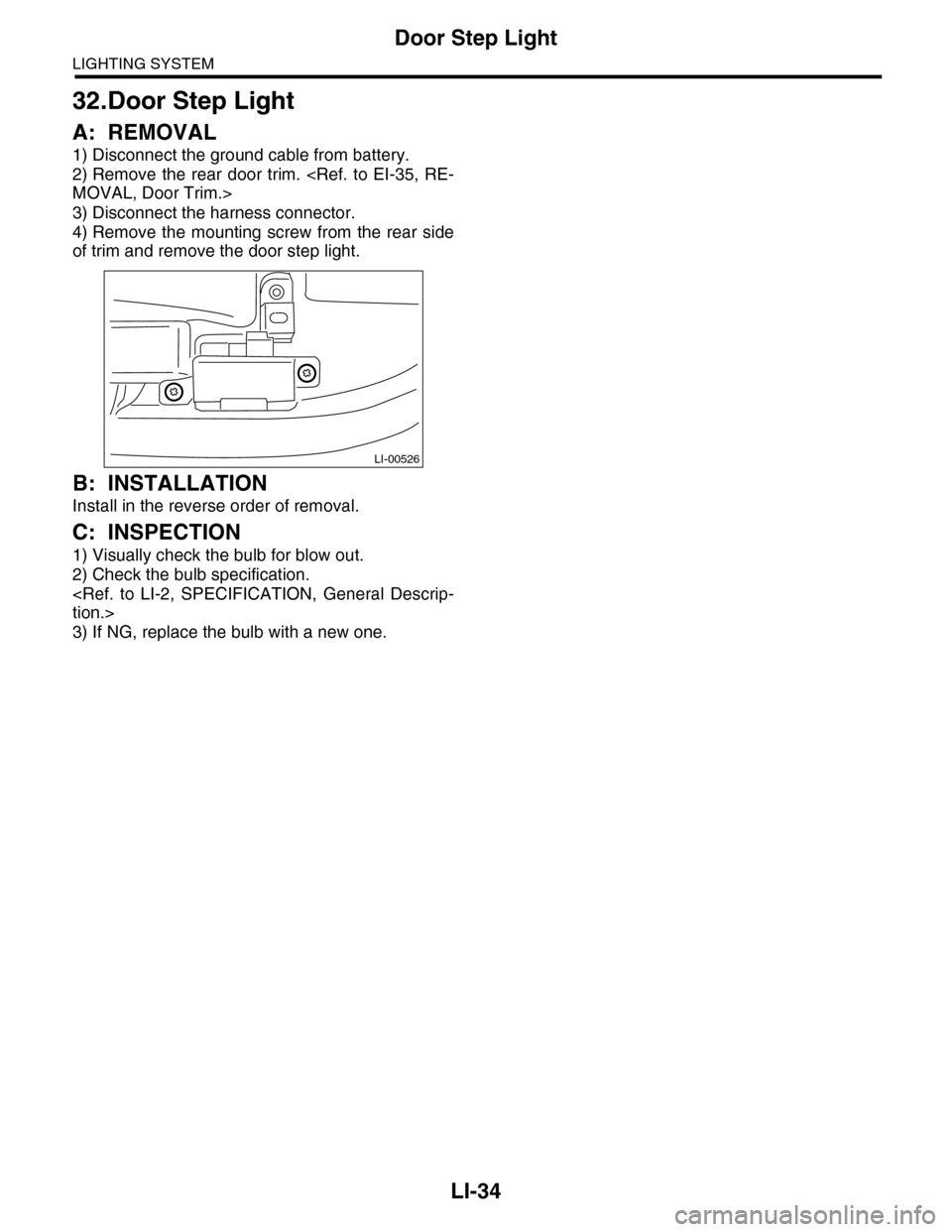
2) Remove the rear door trim.
3) Disconnect the harness connector.
4) Remove the mounting screw from the rear side
of trim and remove the door step light.
B: INSTALLATION
Install in the reverse order of removal.
C: INSPECTION
1) Visually check the bulb for blow out.
2) Check the bulb specification.
3) If NG, replace the bulb with a new one.
LI-00526
Page 568 of 2453
LI-35
Ignition Switch Illumination
LIGHTING SYSTEM
33.Ignition Switch Illumination
A: REMOVAL
1) Disconnect the ground cable from battery.
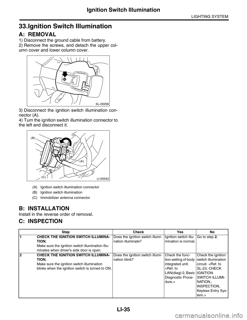
2) Remove the screws, and detach the upper col-
umn cover and lower column cover.
3) Disconnect the ignition switch illumination con-
nector (A).
4) Turn the ignition switch illumination connector to
the left and disconnect it.
B: INSTALLATION
Install in the reverse order of removal.
C: INSPECTION
(A) Ignition switch illumination connector
(B) Ignition switch illumination
(C) Immobilizer antenna connector
SL-00258
LI-00343(C)
(B)
(A)
Step Check Yes No
1CHECK THE IGNITION SWITCH ILLUMINA-
TION.
Make sure the ignition switch illumination illu-
minates when driver’s side door is open.
Does the ignition switch illumi-
nation illuminate?
Ignition switch illu-
mination is normal.
Go to step 2.
2CHECK THE IGNITION SWITCH ILLUMINA-
TION.
Make sure the ignition switch illumination
blinks when the ignition switch is turned to ON.
Does the ignition switch illumi-
nation blink?
Check the func-
tion setting of body
integrated unit.
Diagnostic Proce-
dure.>
Check the ignition
switch illumination
circuit.
IGNITION
SWITCH ILLUMI-
NATION.,
INSPECTION,
Keyless Entr y Sys-
tem.>
Page 569 of 2453

LI-36
Ignition Switch Illumination
LIGHTING SYSTEM
Page 570 of 2453
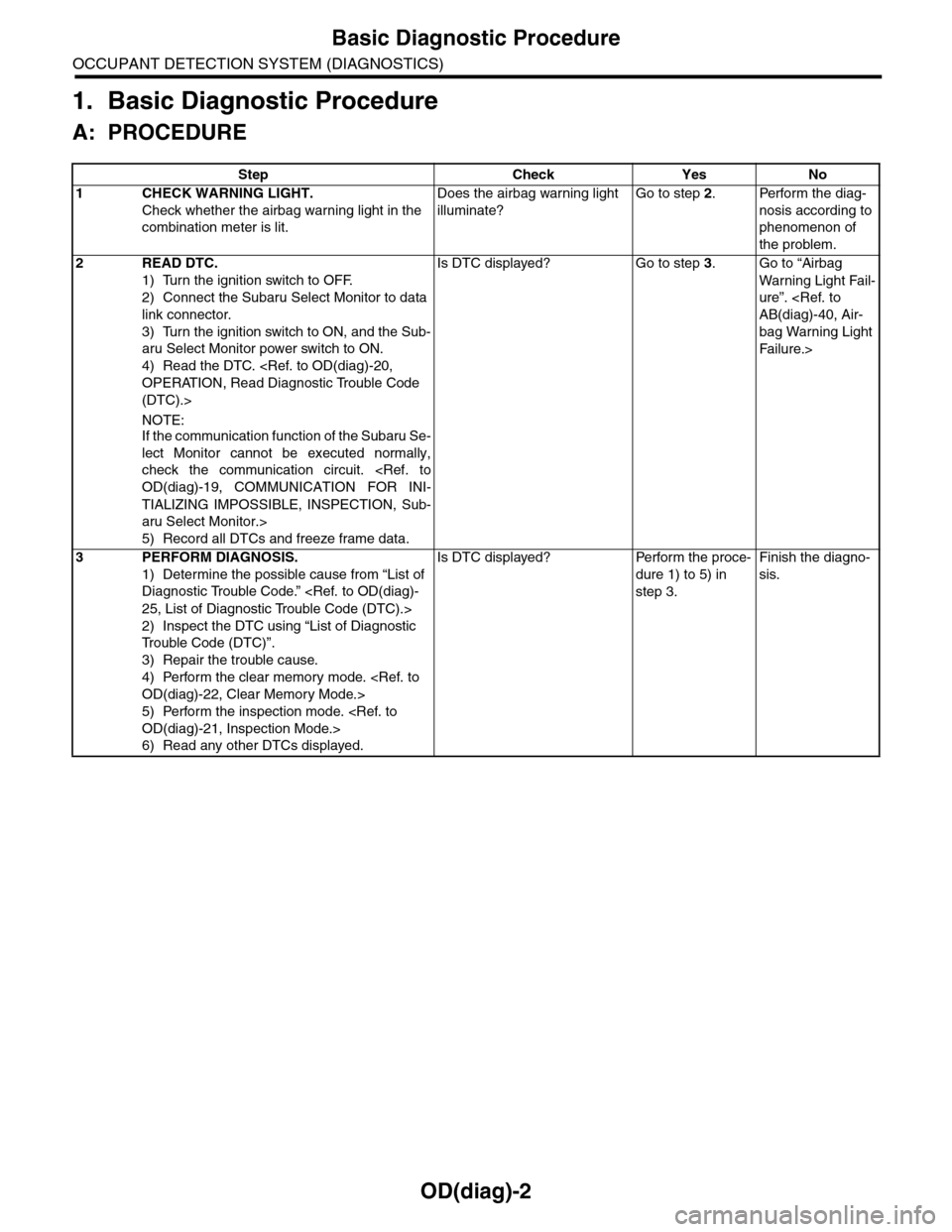
OD(diag)-2
Basic Diagnostic Procedure
OCCUPANT DETECTION SYSTEM (DIAGNOSTICS)
1. Basic Diagnostic Procedure
A: PROCEDURE
Step Check Yes No
1CHECK WARNING LIGHT.
Check whether the airbag warning light in the
combination meter is lit.
Does the airbag warning light
illuminate?
Go to step 2.Perform the diag-
nosis according to
phenomenon of
the problem.
2READ DTC.
1) Turn the ignition switch to OFF.
2) Connect the Subaru Select Monitor to data
link connector.
3) Turn the ignition switch to ON, and the Sub-
aru Select Monitor power switch to ON.
4) Read the DTC.
(DTC).>
NOTE:If the communication function of the Subaru Se-
lect Monitor cannot be executed normally,
check the communication circuit.
TIALIZING IMPOSSIBLE, INSPECTION, Sub-
aru Select Monitor.>
5) Record all DTCs and freeze frame data.
Is DTC displayed? Go to step 3.Go to “Airbag
Wa r ni n g L ig h t Fa i l-
ure”.
bag Warning Light
Fai lu r e.>
3PERFORM DIAGNOSIS.
1) Determine the possible cause from “List of
Diagnostic Trouble Code.”
2) Inspect the DTC using “List of Diagnostic
Tr o u b l e C o d e ( D T C ) ” .
3) Repair the trouble cause.
4) Perform the clear memory mode.
5) Perform the inspection mode.
6) Read any other DTCs displayed.
Is DTC displayed? Perform the proce-
dure 1) to 5) in
step 3.
Finish the diagno-
sis.