sensor SUBARU TRIBECA 2009 1.G Service Workshop Manual
[x] Cancel search | Manufacturer: SUBARU, Model Year: 2009, Model line: TRIBECA, Model: SUBARU TRIBECA 2009 1.GPages: 2453, PDF Size: 46.32 MB
Page 1683 of 2453
GD(H6DO)-71
Diagnostic Trouble Code (DTC) Detecting Criteria
GENERAL DESCRIPTION
AO:DTC P0137 O2 SENSOR CIRCUIT LOW VOLTAGE (BANK 1 SENSOR 2)
1. OUTLINE OF DIAGNOSIS
Detect continuity NG of the oxygen sensor. Judge as NG when the O2 voltage is not within the range of pos-
sible values considering driving condition.
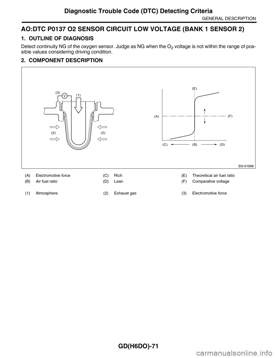
2. COMPONENT DESCRIPTION
(A) Electromotive force (C) Rich (E) Theoretical air fuel ratio
(B) Air fuel ratio (D) Lean (F) Comparative voltage
(1) Atmosphere (2) Exhaust gas (3) Electromotive force
EN-01696
(3)V(1)
(2) (2)
(E)
(F)
(C) (B) (D)
(A)
Page 1684 of 2453
GD(H6DO)-72
Diagnostic Trouble Code (DTC) Detecting Criteria
GENERAL DESCRIPTION
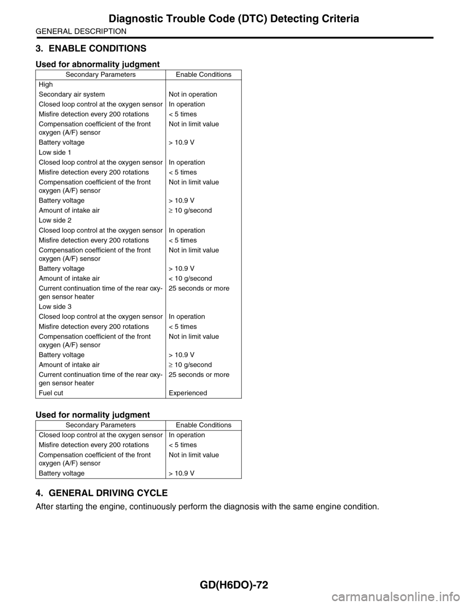
3. ENABLE CONDITIONS
4. GENERAL DRIVING CYCLE
After starting the engine, continuously perform the diagnosis with the same engine condition.
Used for abnormality judgment
Secondary Parameters Enable Conditions
High
Secondary air system Not in operation
Closed loop control at the oxygen sensor In operation
Misfire detection every 200 rotations < 5 times
Compensation coefficient of the front
oxygen (A/F) sensor
Not in limit value
Battery voltage > 10.9 V
Low side 1
Closed loop control at the oxygen sensor In operation
Misfire detection every 200 rotations < 5 times
Compensation coefficient of the front
oxygen (A/F) sensor
Not in limit value
Battery voltage > 10.9 V
Amount of intake air≥ 10 g/second
Low side 2
Closed loop control at the oxygen sensor In operation
Misfire detection every 200 rotations < 5 times
Compensation coefficient of the front
oxygen (A/F) sensor
Not in limit value
Battery voltage > 10.9 V
Amount of intake air < 10 g/second
Current continuation time of the rear oxy-
gen sensor heater
25 seconds or more
Low side 3
Closed loop control at the oxygen sensor In operation
Misfire detection every 200 rotations < 5 times
Compensation coefficient of the front
oxygen (A/F) sensor
Not in limit value
Battery voltage > 10.9 V
Amount of intake air≥ 10 g/second
Current continuation time of the rear oxy-
gen sensor heater
25 seconds or more
Fuel cut Experienced
Used for normality judgment
Secondary Parameters Enable Conditions
Closed loop control at the oxygen sensor In operation
Misfire detection every 200 rotations < 5 times
Compensation coefficient of the front
oxygen (A/F) sensor
Not in limit value
Battery voltage > 10.9 V
Page 1686 of 2453
GD(H6DO)-74
Diagnostic Trouble Code (DTC) Detecting Criteria
GENERAL DESCRIPTION
AP:DTC P0138 O2 SENSOR CIRCUIT HIGH VOLTAGE (BANK 1 SENSOR 2)
1. OUTLINE OF DIAGNOSIS
NOTE:
For the diagnostic procedure, refer to DTC P0137.
Page 1687 of 2453
GD(H6DO)-75
Diagnostic Trouble Code (DTC) Detecting Criteria
GENERAL DESCRIPTION
AQ:DTC P0139 O2 SENSOR CIRCUIT SLOW RESPONSE (BANK 1 SENSOR 2)
1. OUTLINE OF DIAGNOSIS
Detect the slow response of the oxygen sensor.
Judge as NG if either the rich to lean response diagnosis or lean to rich response diagnosis is NG, and Judge
as OK if both are OK.
[Rich → Lean diagnosis response]
1. Measure the response time for oxygen sensor output changes when the A/F ratio changes to rich to lean.
If the measured response time is larger than the threshold value, it is NG. If it is smaller, it is OK.
2. Judge as NG when the oxygen sensor voltage is large (rich) when recovering from a deceleration fuel cut.
[Lean → Rich diagnosis response]
1. Measure the response time for oxygen sensor output changes when the A/F ratio changes to lean to rich.
If the measured response time is larger than the threshold value, it is NG.
2. Judge as NG when the oxygen sensor voltage remains small when recovering from a deceleration fuel cut.
Diagnostic method
Measure the response time of the output change of the oxygen sensor when the A/F ratio changes to rich to
lean. And Judge as NG when the measured response time is larger than the threshold value.
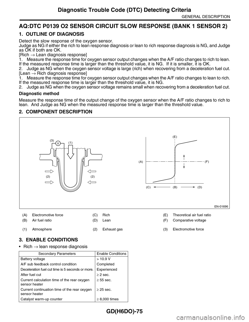
2. COMPONENT DESCRIPTION
3. ENABLE CONDITIONS
•Rich → lean response diagnosis
(A) Electromotive force (C) Rich (E) Theoretical air fuel ratio
(B) Air fuel ratio (D) Lean (F) Comparative voltage
(1) Atmosphere (2) Exhaust gas (3) Electromotive force
Secondary Parameters Enable Conditions
Battery voltage > 10.9 V
A/F sub feedback control condition Completed
Deceleration fuel cut time is 5 seconds or more. Experienced
After fuel cut≥ 2 sec.
Current calculation time of the rear oxygen
sensor heater
≥ 55 sec.
Current continuation time of the rear oxygen
sensor heater
≥ 25 sec.
Catalyst warm-up counter≥ 8,000 times
EN-01696
(3)V(1)
(2) (2)
(E)
(F)
(C) (B) (D)
(A)
Page 1688 of 2453
GD(H6DO)-76
Diagnostic Trouble Code (DTC) Detecting Criteria
GENERAL DESCRIPTION
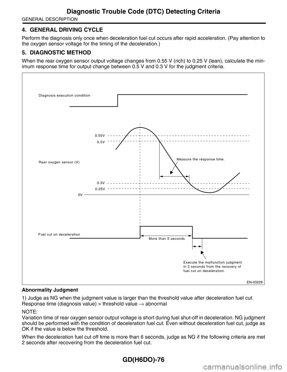
4. GENERAL DRIVING CYCLE
Perform the diagnosis only once when deceleration fuel cut occurs after rapid acceleration. (Pay attention to
the oxygen sensor voltage for the timing of the deceleration.)
5. DIAGNOSTIC METHOD
When the rear oxygen sensor output voltage changes from 0.55 V (rich) to 0.25 V (lean), calculate the min-
imum response time for output change between 0.5 V and 0.3 V for the judgment criteria.
Abnormality Judgment
1) Judge as NG when the judgment value is larger than the threshold value after deceleration fuel cut.
Response time (diagnosis value) > threshold value → abnormal
NOTE:
Variation time of rear oxygen sensor output voltage is short during fuel shut-off in deceleration. NG judgment
should be performed with the condition of deceleration fuel cut. Even without deceleration fuel cut, judge as
OK if the value is below the threshold.
When the deceleration fuel cut off time is more than 6 seconds, judge as NG if the following criteria are met
2 seconds after recovering from the deceleration fuel cut.
0.55V
0.5V
0.3V
0.25V
0V
Diagnosis execution condition
Rear oxygen sensor (V)Measure the response time.
Fuel cut on decelerationMore than 5 seconds
Execute the malfunction judgment in 2 seconds from the recovery of fuel cut on deceleration.
EN-03228
Page 1689 of 2453

GD(H6DO)-77
Diagnostic Trouble Code (DTC) Detecting Criteria
GENERAL DESCRIPTION
2) Judge as NG when the oxygen sensor voltage at recovery from a deceleration fuel cut, is large.
If the fuel cut time in a deceleration fuel cut is long (more than 6 s), and even after recovering from a decel-
eration fuel cut, the oxygen sensor voltage is high (0.55 V or more), judge as NG.
Time Needed for Diagnosis: 1 time
Malfunction Indicator Light Illumination: Illuminates when malfunctions occur in 2 continuous driving cy-
cles.
Normality Judgment
1) Regardless of a deceleration fuel cut, if the response time (diagnosis value) when the oxygen sensor volt-
age has changed from rich to lean is shorter than the threshold value (judgment value), judge as a normal
condition.
Response time (diagnosis value) ≤ threshold value → normal
2) Do not judge as a normal condition.
Judge as OK when the criteria below are met.
6. DTC CLEAR CONDITION
•When the OK idling cycle is completed 40 times in a row
•When “Clear Memory” is performed
7. MALFUNCTION INDICATOR LIGHT CLEAR CONDITIONS
•When the OK driving cycle is completed 3 times in a row
•When “Clear Memory” is performed
8. FAIL SAFE
Sub feedback control: Not allowed
9. ECM OPERATION AT DTC SETTING
•Memorize the freeze frame data. (For test mode $02)
•Memorize the diagnostic value and trouble standard value. (For test mode $06)
10.ENABLE CONDITIONS
•Lean → rich response diagnosis
11.GENERAL DRIVING CYCLE
Perform the diagnosis only once when deceleration fuel cut occurs after rapid acceleration. (Pay attention to
the oxygen sensor voltage for the timing of the deceleration.)
Judgment Value
Malfunction Criteria Threshold Value
Shortest time change from rich (500 mV
O2 output) to lean (300 mV) if voltage
reduces from 550 mV to 250 mV.
> 0.327 sec.
or
Longest time over 550 mV > 2 sec.
Judgment Value
Malfunction Criteria Threshold Value
Shortest time change from rich (500 mV
O2 output) to lean (300 mV) if voltage
reduces from 550 mV to 250 mV.
≤ 0.327 sec.
Secondary Parameters Enable Conditions
Battery voltage > 10.9 V
A/F main feedback control condition Complete
5 seconds or more deceleration fuel cut. Experienced
After fuel cut≥ 2 sec.
Page 1690 of 2453
GD(H6DO)-78
Diagnostic Trouble Code (DTC) Detecting Criteria
GENERAL DESCRIPTION
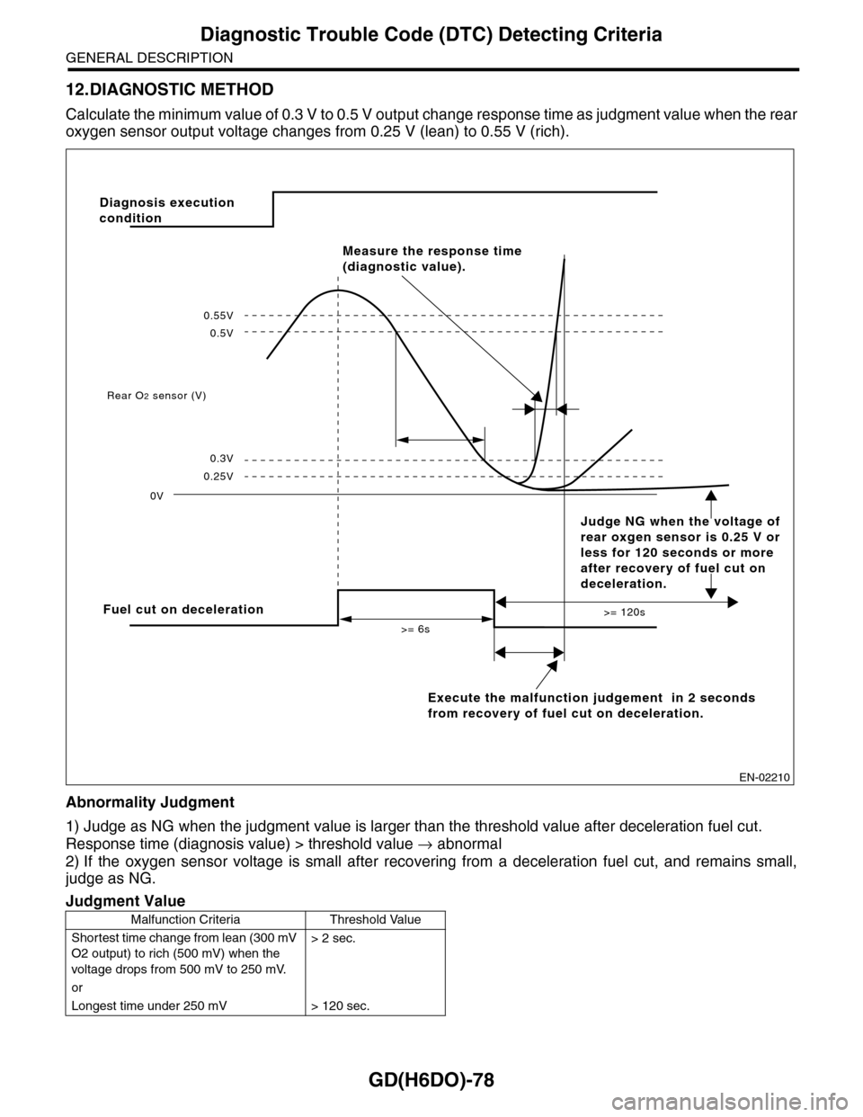
12.DIAGNOSTIC METHOD
Calculate the minimum value of 0.3 V to 0.5 V output ch a n g e r e s p on s e t im e a s ju d g m e n t v a lu e w h en th e re a r
oxygen sensor output voltage changes from 0.25 V (lean) to 0.55 V (rich).
Abnormality Judgment
1) Judge as NG when the judgment value is larger than the threshold value after deceleration fuel cut.
Response time (diagnosis value) > threshold value → abnormal
2) If the oxygen sensor voltage is small after recovering from a deceleration fuel cut, and remains small,
judge as NG.
Judgment Value
Malfunction Criteria Threshold Value
Shortest time change from lean (300 mV
O2 output) to rich (500 mV) when the
voltage drops from 500 mV to 250 mV.
> 2 sec.
or
Longest time under 250 mV > 120 sec.
EN-02210
Fuel cut on deceleration
Execute the malfunction judgement in 2 seconds
from recovery of fuel cut on deceleration.
Rear O2 sensor (V)
0V
>= 6s
>= 120s
0.25V
0.3V
0.5V
0.55V
Measure the response time
(diagnostic value).
Diagnosis execution
condition
Judge NG when the voltage of
rear oxgen sensor is 0.25 V or
less for 120 seconds or more
after recovery of fuel cut on
deceleration.
Page 1691 of 2453
GD(H6DO)-79
Diagnostic Trouble Code (DTC) Detecting Criteria
GENERAL DESCRIPTION
Time Needed for Diagnosis: 1 time
Malfunction Indicator Light Illumination: Illuminates when malfunctions occur in 2 continuous driving cy-
cles.
Normality Judgment
1) Regardless of a deceleration fuel cut, if the response time (diagnosis value) when the oxygen sensor volt-
age has changed from rich to lean is shorter than the threshold value (judgment value), judge as a normal
condition.
Response time (diagnosis value) ≤ threshold value → normal
2) Do not judge as a normal condition.
Judge as OK when the criteria below are met.
13.DTC CLEAR CONDITION
•When the OK idling cycle is completed 40 times in a row
•When “Clear Memory” is performed
14.MALFUNCTION INDICATOR LIGHT CLEAR CONDITIONS
•When the OK driving cycle is completed 3 times in a row
•When “Clear Memory” is performed
15.FAIL SAFE
Sub feedback control: Not allowed
16.ECM OPERATION AT DTC SETTING
•Memorize the freeze frame data. (For test mode $02)
•Memorize the diagnostic value and trouble standard value. (For test mode $06)
Judgment Value
Malfunction Criteria Threshold Value
Shortest time change from lean (300 mV
O2 output) to rich (500 mV) when volt-
age drops from 550 mV to 250 mV.
≤ 2 sec.
Page 1692 of 2453
GD(H6DO)-80
Diagnostic Trouble Code (DTC) Detecting Criteria
GENERAL DESCRIPTION
AR:DTC P0140 O2 SENSOR CIRCUIT NO ACTIVITY DETECTED (BANK 1 SEN-
SOR 2)
1. OUTLINE OF DIAGNOSIS
Detect the rear oxygen sensor open or short circuit. Judge as NG when the rear oxygen sensor voltage can
be determined to be abnormal considering conditions such as intake air amount, engine coolant tempera-
ture, main feedback control and deceleration fuel cut.
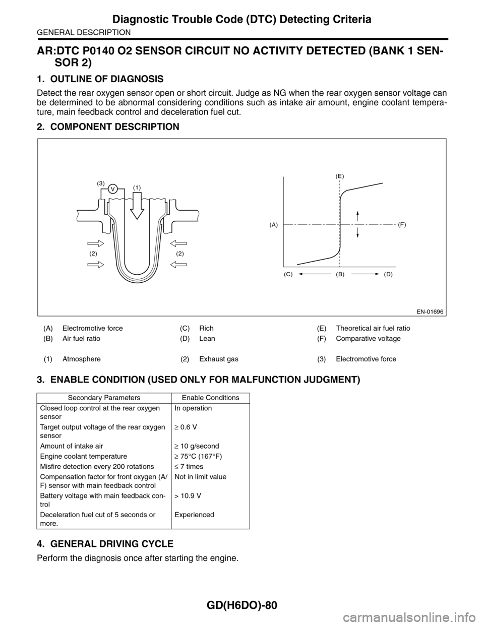
2. COMPONENT DESCRIPTION
3. ENABLE CONDITION (USED ONLY FOR MALFUNCTION JUDGMENT)
4. GENERAL DRIVING CYCLE
Perform the diagnosis once after starting the engine.
(A) Electromotive force (C) Rich (E) Theoretical air fuel ratio
(B) Air fuel ratio (D) Lean (F) Comparative voltage
(1) Atmosphere (2) Exhaust gas (3) Electromotive force
Secondary Parameters Enable Conditions
Closed loop control at the rear oxygen
sensor
In operation
Ta r g e t o u t p u t v o l t a g e o f t h e r e a r o x y g e n
sensor
≥ 0.6 V
Amount of intake air≥ 10 g/second
Engine coolant temperature≥ 75°C (167°F)
Misfire detection every 200 rotations≤ 7 times
Compensation factor for front oxygen (A/
F) sensor with main feedback control
Not in limit value
Battery voltage with main feedback con-
trol
> 10.9 V
Deceleration fuel cut of 5 seconds or
more.
Experienced
EN-01696
(3)V(1)
(2) (2)
(E)
(F)
(C) (B) (D)
(A)
Page 1693 of 2453
GD(H6DO)-81
Diagnostic Trouble Code (DTC) Detecting Criteria
GENERAL DESCRIPTION
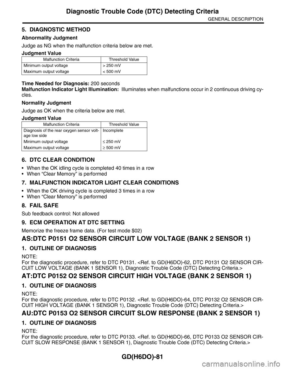
5. DIAGNOSTIC METHOD
Abnormality Judgment
Judge as NG when the malfunction criteria below are met.
Time Needed for Diagnosis: 200 seconds
Malfunction Indicator Light Illumination: Illuminates when malfunctions occur in 2 continuous driving cy-
cles.
Normality Judgment
Judge as OK when the criteria below are met.
6. DTC CLEAR CONDITION
•When the OK idling cycle is completed 40 times in a row
•When “Clear Memory” is performed
7. MALFUNCTION INDICATOR LIGHT CLEAR CONDITIONS
•When the OK driving cycle is completed 3 times in a row
•When “Clear Memory” is performed
8. FAIL SAFE
Sub feedback control: Not allowed
9. ECM OPERATION AT DTC SETTING
Memorize the freeze frame data. (For test mode $02)
AS:DTC P0151 O2 SENSOR CIRCUIT LOW VOLTAGE (BANK 2 SENSOR 1)
1. OUTLINE OF DIAGNOSIS
NOTE:
For the diagnostic procedure, refer to DTC P0131.
AT:DTC P0152 O2 SENSOR CIRCUIT HIGH VOLTAGE (BANK 2 SENSOR 1)
1. OUTLINE OF DIAGNOSIS
NOTE:
For the diagnostic procedure, refer to DTC P0132.
AU:DTC P0153 O2 SENSOR CIRCUIT SLOW RESPONSE (BANK 2 SENSOR 1)
1. OUTLINE OF DIAGNOSIS
NOTE:
For the diagnostic procedure, refer to DTC P0133.
Judgment Value
Malfunction Criteria Threshold Value
Minimum output voltage > 250 mV
Maximum output voltage < 500 mV
Judgment Value
Malfunction Criteria Threshold Value
Diagnosis of the rear oxygen sensor volt-
age low side
Incomplete
Minimum output voltage≤ 250 mV
Maximum output voltage≥ 500 mV