sensor SUBARU TRIBECA 2009 1.G Service Workshop Manual
[x] Cancel search | Manufacturer: SUBARU, Model Year: 2009, Model line: TRIBECA, Model: SUBARU TRIBECA 2009 1.GPages: 2453, PDF Size: 46.32 MB
Page 1669 of 2453
GD(H6DO)-57
Diagnostic Trouble Code (DTC) Detecting Criteria
GENERAL DESCRIPTION
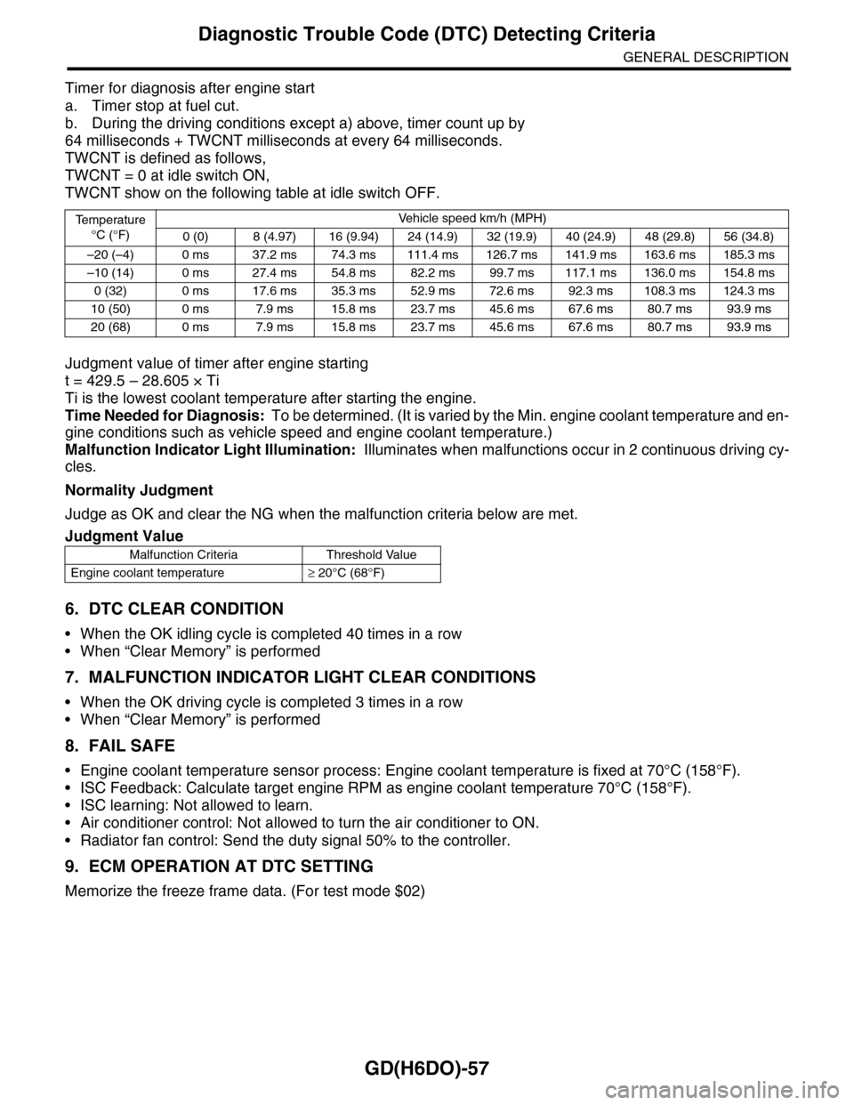
Timer for diagnosis after engine start
a. Timer stop at fuel cut.
b. During the driving conditions except a) above, timer count up by
64 milliseconds + TWCNT milliseconds at every 64 milliseconds.
TWCNT is defined as follows,
TWCNT = 0 at idle switch ON,
TWCNT show on the following table at idle switch OFF.
Judgment value of timer after engine starting
t = 429.5 – 28.605 × Ti
Ti is the lowest coolant temperature after starting the engine.
Time Needed for Diagnosis: To be determined. (It is varied by the Min. engine coolant temperature and en-
gine conditions such as vehicle speed and engine coolant temperature.)
Malfunction Indicator Light Illumination: Illuminates when malfunctions occur in 2 continuous driving cy-
cles.
Normality Judgment
Judge as OK and clear the NG when the malfunction criteria below are met.
6. DTC CLEAR CONDITION
•When the OK idling cycle is completed 40 times in a row
•When “Clear Memory” is performed
7. MALFUNCTION INDICATOR LIGHT CLEAR CONDITIONS
•When the OK driving cycle is completed 3 times in a row
•When “Clear Memory” is performed
8. FAIL SAFE
•Engine coolant temperature sensor process: Engine coolant temperature is fixed at 70°C (158°F).
•ISC Feedback: Calculate target engine RPM as engine coolant temperature 70°C (158°F).
•ISC learning: Not allowed to learn.
•Air conditioner control: Not allowed to turn the air conditioner to ON.
•Radiator fan control: Send the duty signal 50% to the controller.
9. ECM OPERATION AT DTC SETTING
Memorize the freeze frame data. (For test mode $02)
Te m p e r a t u r e
°C (°F)
Ve h i c l e s p e e d k m / h ( M P H )
0 (0) 8 (4.97) 16 (9.94) 24 (14.9) 32 (19.9) 40 (24.9) 48 (29.8) 56 (34.8)
–20 (–4) 0 ms 37.2 ms 74.3 ms 111.4 ms 126.7 ms 141.9 ms 163.6 ms 185.3 ms
–10 (14) 0 ms 27.4 ms 54.8 ms 82.2 ms 99.7 ms 117.1 ms 136.0 ms 154.8 ms
0 (32) 0 ms 17.6 ms 35.3 ms 52.9 ms 72.6 ms 92.3 ms 108.3 ms 124.3 ms
10 (50) 0 ms 7.9 ms 15.8 ms 23.7 ms 45.6 ms 67.6 ms 80.7 ms 93.9 ms
20 (68) 0 ms 7.9 ms 15.8 ms 23.7 ms 45.6 ms 67.6 ms 80.7 ms 93.9 ms
Judgment Value
Malfunction Criteria Threshold Value
Engine coolant temperature≥ 20°C (68°F)
Page 1670 of 2453
GD(H6DO)-58
Diagnostic Trouble Code (DTC) Detecting Criteria
GENERAL DESCRIPTION
AI: DTC P0126 INSUFFICIENT COOLANT TEMPERATURE FOR STABLE OPER-
ATION
1. OUTLINE OF DIAGNOSIS
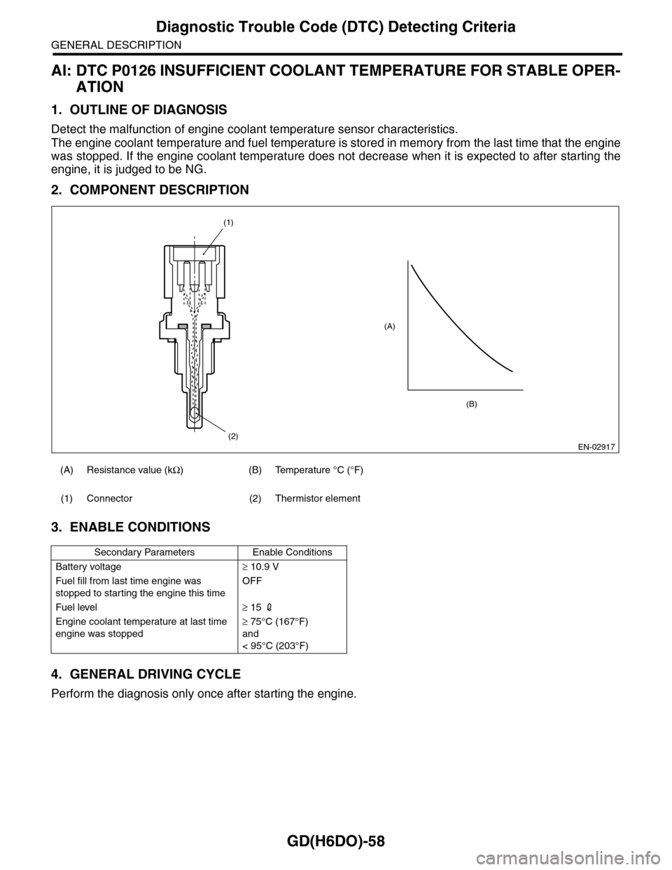
Detect the malfunction of engine coolant temperature sensor characteristics.
The engine coolant temperature and fuel temperature is stored in memory from the last time that the engine
was stopped. If the engine coolant temperature does not decrease when it is expected to after starting the
engine, it is judged to be NG.
2. COMPONENT DESCRIPTION
3. ENABLE CONDITIONS
4. GENERAL DRIVING CYCLE
Perform the diagnosis only once after starting the engine.
(A) Resistance value (kΩ)(B)Temperature °C (°F)
(1) Connector (2) Thermistor element
Secondary Parameters Enable Conditions
Battery voltage≥ 10.9 V
Fuel fill from last time engine was
stopped to starting the engine this time
OFF
Fuel level≥ 15 2
Engine coolant temperature at last time
engine was stopped
≥ 75°C (167°F)
and
< 95°C (203°F)
EN-02917
(A)
(2)
(1)
(B)
Page 1674 of 2453
GD(H6DO)-62
Diagnostic Trouble Code (DTC) Detecting Criteria
GENERAL DESCRIPTION
AK:DTC P0131 O2 SENSOR CIRCUIT LOW VOLTAGE (BANK 1 SENSOR 1)
1. OUTLINE OF DIAGNOSIS
Detect the open or short circuit of sensor.
Judge as NG when the element impressed voltage is out of range, or the element current is out of range.
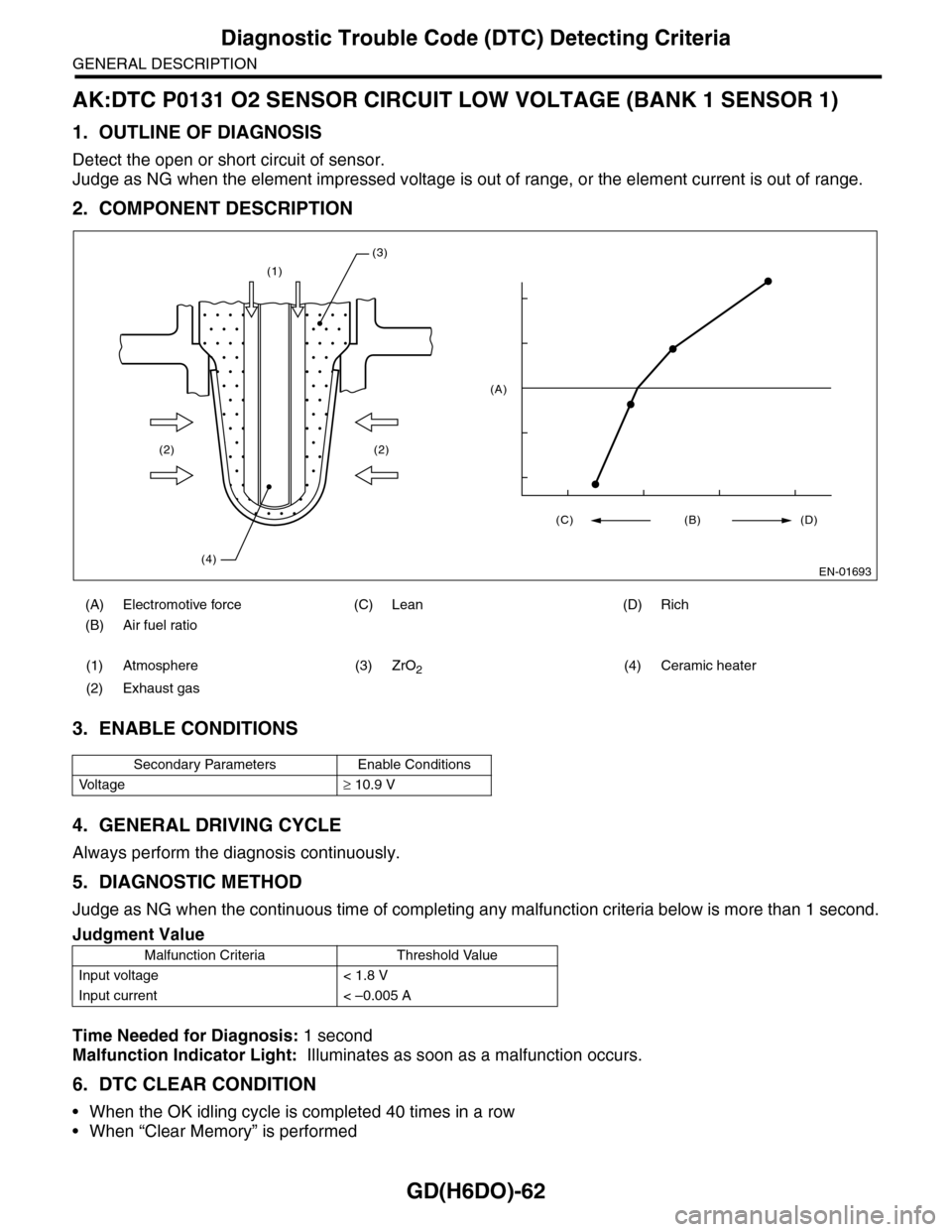
2. COMPONENT DESCRIPTION
3. ENABLE CONDITIONS
4. GENERAL DRIVING CYCLE
Always perform the diagnosis continuously.
5. DIAGNOSTIC METHOD
Judge as NG when the continuous time of completing any malfunction criteria below is more than 1 second.
Time Needed for Diagnosis: 1 second
Malfunction Indicator Light: Illuminates as soon as a malfunction occurs.
6. DTC CLEAR CONDITION
•When the OK idling cycle is completed 40 times in a row
•When “Clear Memory” is performed
(A) Electromotive force (C) Lean (D) Rich
(B) Air fuel ratio
(1) Atmosphere (3) ZrO2(4) Ceramic heater
(2) Exhaust gas
Secondary Parameters Enable Conditions
Vo l t a g e≥ 10.9 V
Judgment Value
Malfunction Criteria Threshold Value
Input voltage < 1.8 V
Input current < –0.005 A
(1)
(2)
(4)
(2)
(3)
EN-01693
(C) (B) (D)
(A)
Page 1675 of 2453
GD(H6DO)-63
Diagnostic Trouble Code (DTC) Detecting Criteria
GENERAL DESCRIPTION
7. MALFUNCTION INDICATOR LIGHT CLEAR CONDITIONS
•When the OK driving cycle is completed 3 times in a row
•When “Clear Memory” is performed
8. FAIL SAFE
•Front oxygen (A/F) sensor heater control: Prohibit heater continuity.
•A/F main learning: Not allowed to calculate the A/F main learning compensation factor.
•A/F sub learning: Not allowed to calculate the A/F sub learning compensation factor.
•Purge control: Not allowed to purge
9. ECM OPERATION AT DTC SETTING
Memorize the freeze frame data. (For test mode $02)
Page 1676 of 2453
GD(H6DO)-64
Diagnostic Trouble Code (DTC) Detecting Criteria
GENERAL DESCRIPTION
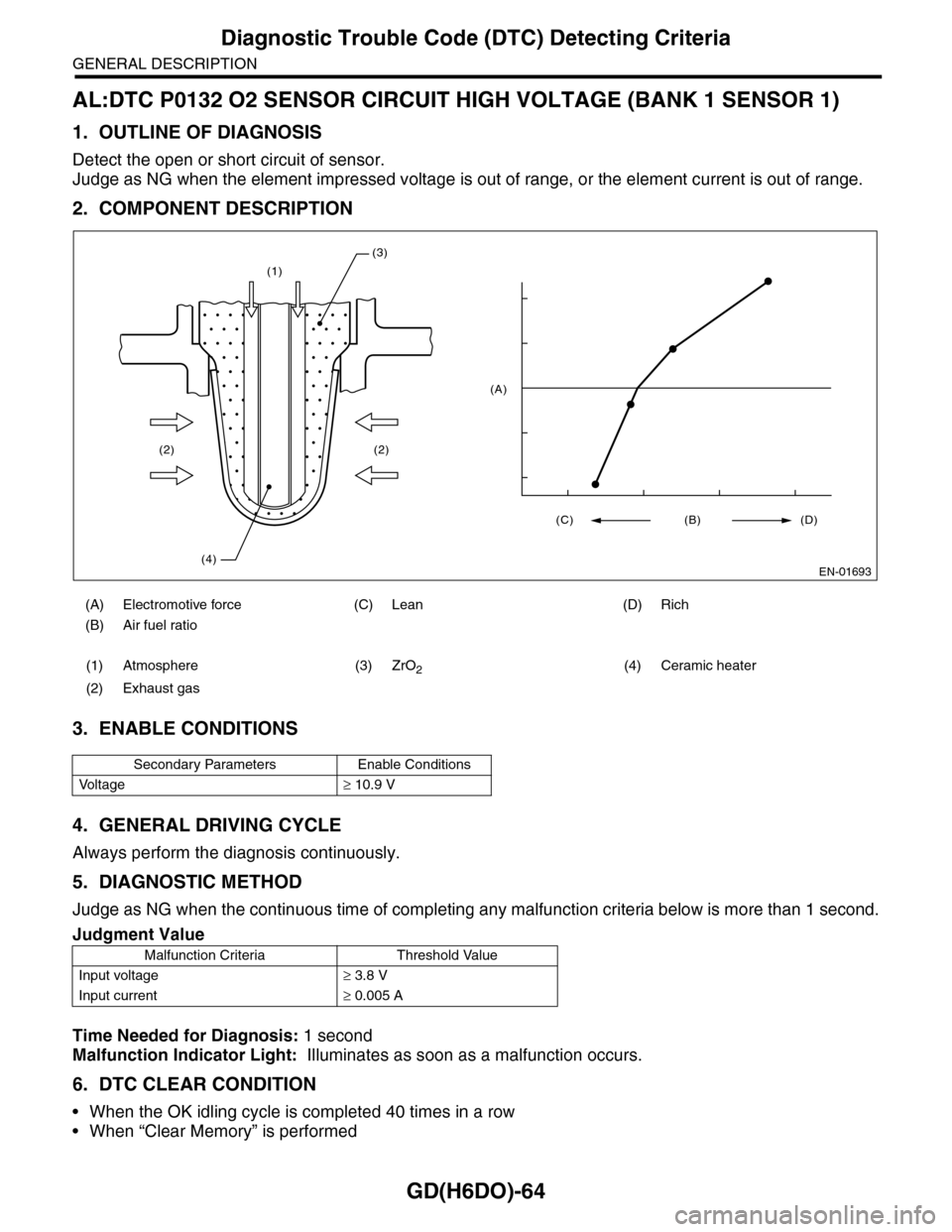
AL:DTC P0132 O2 SENSOR CIRCUIT HIGH VOLTAGE (BANK 1 SENSOR 1)
1. OUTLINE OF DIAGNOSIS
Detect the open or short circuit of sensor.
Judge as NG when the element impressed voltage is out of range, or the element current is out of range.
2. COMPONENT DESCRIPTION
3. ENABLE CONDITIONS
4. GENERAL DRIVING CYCLE
Always perform the diagnosis continuously.
5. DIAGNOSTIC METHOD
Judge as NG when the continuous time of completing any malfunction criteria below is more than 1 second.
Time Needed for Diagnosis: 1 second
Malfunction Indicator Light: Illuminates as soon as a malfunction occurs.
6. DTC CLEAR CONDITION
•When the OK idling cycle is completed 40 times in a row
•When “Clear Memory” is performed
(A) Electromotive force (C) Lean (D) Rich
(B) Air fuel ratio
(1) Atmosphere (3) ZrO2(4) Ceramic heater
(2) Exhaust gas
Secondary Parameters Enable Conditions
Vo l t a g e≥ 10.9 V
Judgment Value
Malfunction Criteria Threshold Value
Input voltage≥ 3.8 V
Input current≥ 0.005 A
(1)
(2)
(4)
(2)
(3)
EN-01693
(C) (B) (D)
(A)
Page 1677 of 2453
GD(H6DO)-65
Diagnostic Trouble Code (DTC) Detecting Criteria
GENERAL DESCRIPTION
7. MALFUNCTION INDICATOR LIGHT CLEAR CONDITIONS
•When the OK driving cycle is completed 3 times in a row
•When “Clear Memory” is performed
8. FAIL SAFE
•Front oxygen (A/F) sensor heater control: Prohibit heater continuity.
•A/F main learning: Not allowed to calculate the A/F main learning compensation factor.
•A/F sub learning: Not allowed to calculate the A/F sub learning compensation factor.
•Purge control: Not allowed to purge
9. ECM OPERATION AT DTC SETTING
Memorize the freeze frame data. (For test mode $02)
Page 1678 of 2453
GD(H6DO)-66
Diagnostic Trouble Code (DTC) Detecting Criteria
GENERAL DESCRIPTION
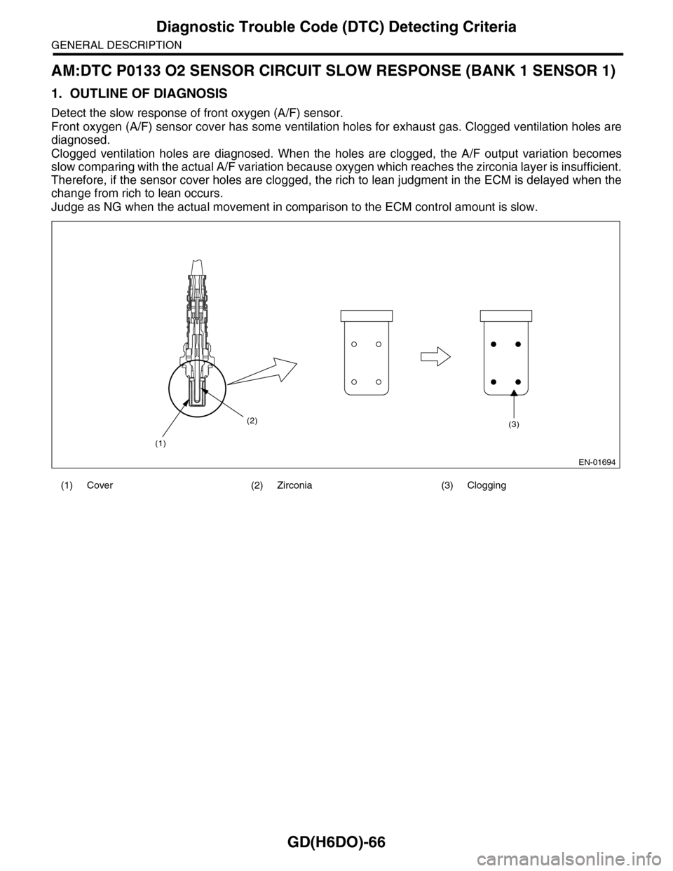
AM:DTC P0133 O2 SENSOR CIRCUIT SLOW RESPONSE (BANK 1 SENSOR 1)
1. OUTLINE OF DIAGNOSIS
Detect the slow response of front oxygen (A/F) sensor.
Front oxygen (A/F) sensor cover has some ventilation holes for exhaust gas. Clogged ventilation holes are
diagnosed.
Clogged ventilation holes are diagnosed. When the holes are clogged, the A/F output variation becomes
slow comparing with the actual A/F variation because oxygen which reaches the zirconia layer is insufficient.
Therefore, if the sensor cover holes are clogged, the rich to lean judgment in the ECM is delayed when the
change from rich to lean occurs.
Judge as NG when the actual movement in comparison to the ECM control amount is slow.
(1) Cover (2) Zirconia (3) Clogging
EN-01694
(1)
(2)(3)
Page 1680 of 2453
GD(H6DO)-68
Diagnostic Trouble Code (DTC) Detecting Criteria
GENERAL DESCRIPTION
5. DIAGNOSTIC METHOD
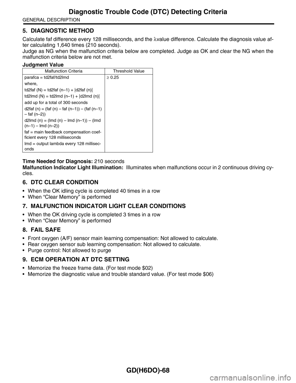
Calculate faf difference every 128 milliseconds, and the λvalue difference. Calculate the diagnosis value af-
ter calculating 1,640 times (210 seconds).
Judge as NG when the malfunction criteria below are completed. Judge as OK and clear the NG when the
malfunction criteria below are not met.
Time Needed for Diagnosis: 210 seconds
Malfunction Indicator Light Illumination: Illuminates when malfunctions occur in 2 continuous driving cy-
cles.
6. DTC CLEAR CONDITION
•When the OK idling cycle is completed 40 times in a row
•When “Clear Memory” is performed
7. MALFUNCTION INDICATOR LIGHT CLEAR CONDITIONS
•When the OK driving cycle is completed 3 times in a row
•When “Clear Memory” is performed
8. FAIL SAFE
•Front oxygen (A/F) sensor main learning compensation: Not allowed to calculate.
•Rear oxygen sensor sub learning compensation: Not allowed to calculate.
•Purge control: Not allowed to purge
9. ECM OPERATION AT DTC SETTING
•Memorize the freeze frame data. (For test mode $02)
•Memorize the diagnostic value and trouble standard value. (For test mode $06)
Judgment Value
Malfunction Criteria Threshold Value
parafca = td2faf/td2lmd≥ 0.25
where,
td2faf (N) = td2faf (n–1) + |d2faf (n)|
td2lmd (N) = td2lmd (n–1) + |d2lmd (n)|
add up for a total of 300 seconds
d2faf (n) = (faf (n) – faf (n–1)) – (faf (n–1)
– faf (n–2))
d2lmd (n) = (lmd (n) – lmd (n–1)) – (lmd
(n–1) – lmd (n–2))
faf = main feedback compensation coef-
ficient every 128 milliseconds
lmd = output lambda every 128 millisec-
onds
Page 1681 of 2453
GD(H6DO)-69
Diagnostic Trouble Code (DTC) Detecting Criteria
GENERAL DESCRIPTION
AN:DTC P0134 O2 SENSOR CIRCUIT NO ACTIVITY DETECTED (BANK 1 SEN-
SOR 1)
1. OUTLINE OF DIAGNOSIS
Detect open circuits of the sensor.
Judge as NG when the impedance of the element is large.
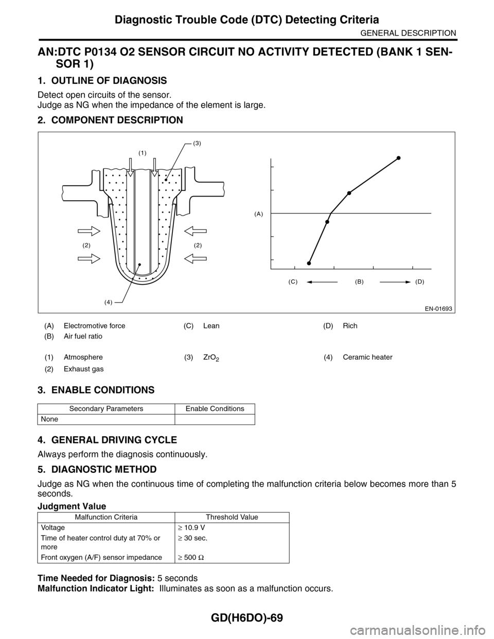
2. COMPONENT DESCRIPTION
3. ENABLE CONDITIONS
4. GENERAL DRIVING CYCLE
Always perform the diagnosis continuously.
5. DIAGNOSTIC METHOD
Judge as NG when the continuous time of completing the malfunction criteria below becomes more than 5
seconds.
Time Needed for Diagnosis: 5 seconds
Malfunction Indicator Light: Illuminates as soon as a malfunction occurs.
(A) Electromotive force (C) Lean (D) Rich
(B) Air fuel ratio
(1) Atmosphere (3) ZrO2(4) Ceramic heater
(2) Exhaust gas
Secondary Parameters Enable Conditions
None
Judgment Value
Malfunction Criteria Threshold Value
Vo l t a g e≥ 10.9 V
Time of heater control duty at 70% or
more
≥ 30 sec.
Fr o nt ox yg e n ( A / F) s en so r im pe d an c e≥ 500 Ω
(1)
(2)
(4)
(2)
(3)
EN-01693
(C) (B) (D)
(A)
Page 1682 of 2453
GD(H6DO)-70
Diagnostic Trouble Code (DTC) Detecting Criteria
GENERAL DESCRIPTION
6. DTC CLEAR CONDITION
•When the OK idling cycle is completed 40 times in a row
•When “Clear Memory” is performed
7. MALFUNCTION INDICATOR LIGHT CLEAR CONDITIONS
•When the OK driving cycle is completed 3 times in a row
•When “Clear Memory” is performed
8. FAIL SAFE
•Front oxygen (A/F) sensor main learning compensation: Not allowed to calculate.
•Purge control: Not allowed to purge
9. ECM OPERATION AT DTC SETTING
Memorize the freeze frame data. (For test mode $02)