Rear diff SUBARU TRIBECA 2009 1.G Service Repair Manual
[x] Cancel search | Manufacturer: SUBARU, Model Year: 2009, Model line: TRIBECA, Model: SUBARU TRIBECA 2009 1.GPages: 2453, PDF Size: 46.32 MB
Page 935 of 2453
RS-2
General Description
REAR SUSPENSION
1. General Description
A: SPECIFICATION
NOTE:
•Front and rear toe–in and front camber can be
adjusted. Adjust if the toe–in or camber tolerance
exceeds specifications.
•Other items indicated in the specifications table
cannot be adjusted. If other items exceed specifica-
tions, check the suspension parts and connections
for deformation, and replace with new ones as re-
quired.
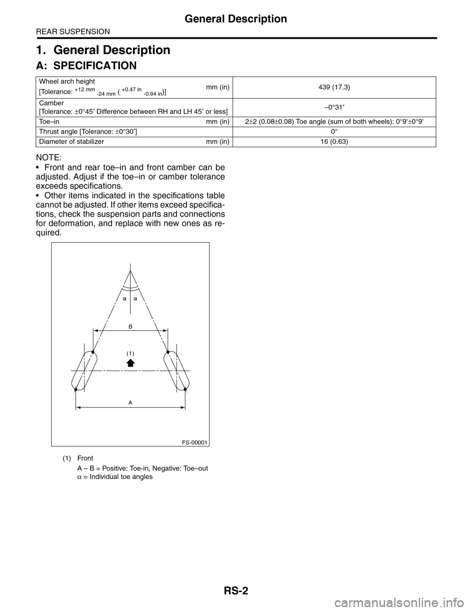
Wheel arch height
[Tolerance: +12 mm -24 mm ( +0.47 in -0.94 in)]mm (in) 439 (17.3)
Camber
[Tolerance: ±0°45′ Difference between RH and LH 45′ or less]–0°31′
To e – i n m m ( i n ) 2±2 (0.08±0.08) Toe angle (sum of both wheels): 0°9'±0°9'
Thrust angle [Tolerance: ±0°30′]0°
Diameter of stabilizer mm (in) 16 (0.63)
(1) Front
A – B = Positive: Toe-in, Negative: Toe–out
α = Individual toe angles
FS-00001
B
A
(1)
Page 939 of 2453
RS-6
General Description
REAR SUSPENSION
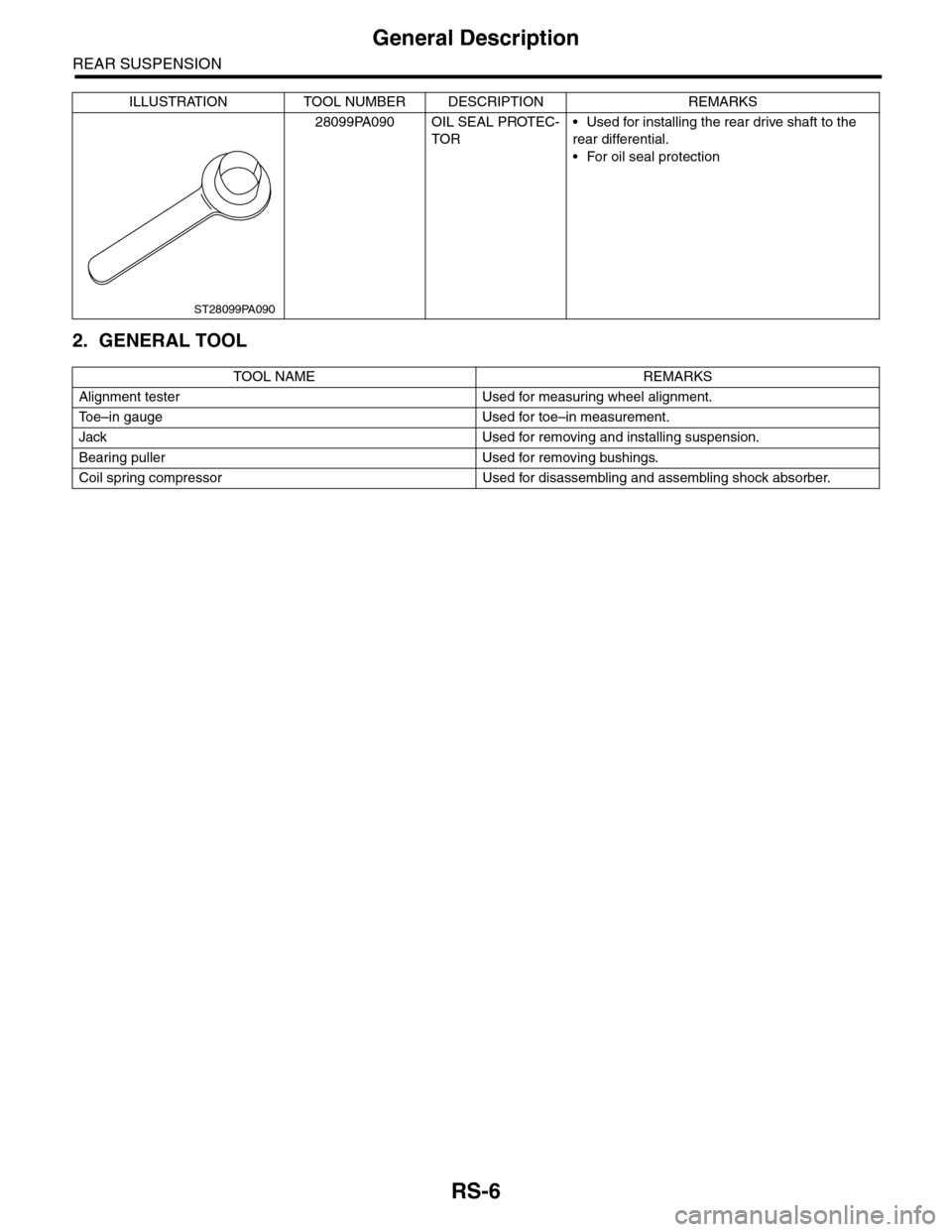
2. GENERAL TOOL
28099PA090 OIL SEAL PROTEC-
TOR
•Used for installing the rear drive shaft to the
rear differential.
•For oil seal protection
TOOL NAME REMARKS
Alignment tester Used for measuring wheel alignment.
To e – i n g a u g e U s e d f o r t o e – i n m e a s u r e m e n t .
Jack Used for removing and installing suspension.
Bearing puller Used for removing bushings.
Coil spring compressor Used for disassembling and assembling shock absorber.
ILLUSTRATION TOOL NUMBER DESCRIPTION REMARKS
ST28099PA090
Page 953 of 2453
TPM(diag)-3
General Description
TIRE PRESSURE MONITORING SYSTEM (DIAGNOSTICS)
2. General Description
A: CAUTION
1. SRS AIRBAG SYSTEM
Airbag system wiring harness is routed near the
TPM control module.
CAUTION:
•Wiring harnesses of all airbag system are yel-
low. Do not use the electrical test equipment on
these circuits.
•Be careful not to damage the airbag system
wiring harness when servicing the tire pressure
monitoring control module.
2. TIRE PRESSURE MONITORING CON-
TROL MODULE
•If the alteration of tire rotation, the installation po-
sition or the replacement of transmitter is per-
formed, ID registration for the transmitter is
required.
Monitor.>
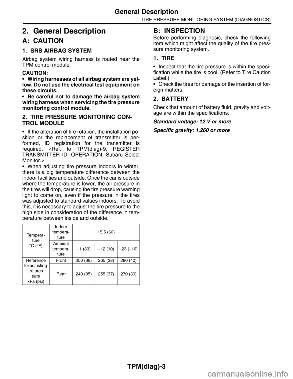
•When adjusting tire pressure indoors in winter,
there is a big temperature difference between the
indoor facilities and outside. Once the car is outside
where the temperature is lower, the air pressure in
the tires will drop, causing the tire pressure warning
light to come on, even if the pressure in the tires
was adjusted to standard values indoors. To avoid
this, it is necessary to adjust the tire pressure to the
high side in consideration of the difference in tem-
perature between inside and outside.
B: INSPECTION
Before performing diagnosis, check the following
item which might affect the quality of the tire pres-
sure monitoring system.
1. TIRE
•Inspect that the tire pressure is within the speci-
fication while the tire is cool. (Refer to Tire Caution
Label.)
•Check the tires for damage or the insertion of for-
eign matters.
2. BATTERY
Check that amount of battery fluid, gravity and volt-
age are within the specifications.
Standard voltage: 12 V or more
Specific gravity: 1.260 or more
Te m p e r a -
ture
°C (°F)
Indoor
tempera-
ture
15.5 (60)
Ambient
tempera-
ture
–1 (30) –12 (10) –23 (–10)
Reference
for adjusting
tire pres-
sure
kPa (psi)
Fr o n t 25 0 ( 36 ) 26 5 ( 3 8 ) 2 8 0 ( 4 0)
Rear 240 (35) 255 (37) 270 (39)
Page 1166 of 2453
EN(H6DO)(diag)-5
General Description
ENGINE (DIAGNOSTICS)
3. General Description
A: CAUTION
1) Airbag system wiring harness is routed near the
ECM, main relay and fuel pump relay.
CAUTION:
•All airbag system wiring harnesses and con-
nectors are colored yellow. Do not use electri-
cal test equipment on these circuits.
•Be careful not to damage the airbag system
wiring harness when servicing the ECM, TCM,
main relay and fuel pump relay.
2) Never connect the battery in reverse polarity.
•The ECM will be destroyed instantly.
•The fuel injector and other parts will be dam-
aged.
3) Do not disconnect the battery terminals while the
engine is running.
A large counter electromotive force will be generat-
ed in the generator, and this voltage may damage
electronic parts such as ECM etc.
4) Before disconnecting the connectors of each
sensor and ECM, be sure to turn the ignition switch
to OFF. Perform the clear memory mode after con-
necting the connectors.
5) Poor contact has been identified as a primary
cause of this problem. Measure the voltage or re-
sistance of individual sensor or all electrical control
modules using a tapered pin with a diameter of less
than 0.64 mm (0.025 in). Do not insert the pin more
than 5 mm (0.20 in) into the part.
6) Remove the ECM from the located position after
disconnecting two cables on battery.
Otherwise, the ECM may be damaged.
CAUTION:
When replacing the ECM, be careful not to use
the wrong spec. ECM to avoid any damage on
the fuel injection system.
7) Connectors of each sensor in the engine com-
partment and the harness connectors on the en-
gine side and body side are all designed to be
waterproof. Even if the connectors are waterproof,
take care not to allow water to get into them when
washing the vehicle, or when servicing the vehicle
in rainy weather.
8) Use ECM mounting stud bolts as the grounding
point to chassis when measuring voltage and resis-
tance in the passenger compartment.
9) Use the engine ground terminal or engine as-
sembly as the grounding point to chassis when
measuring the voltage and resistance in engine
compartment.
10) Every MFI-related part is a precision part. Do
not drop them.
11) Observe the following cautions when installing
a radio in MFI equipped models.
CAUTION:
•The antenna must be kept as far apart as pos-
sible from control unit. (The ECM is located un-
der the steering column, inside of the
instrument panel lower trim panel.)
•The antenna feeder must be placed as far apart
as possible from the ECM and MFI harness.
•Carefully adjust the antenna for correct
matching.
•When mounting a large power type radio, pay
special attention to the three items mentioned
above.
•Incorrect installation of the radio may affect
the operation of ECM.
12) Release the pressure in the fuel system before
disconnecting the fuel hose. If engine starts during
this operation, run it until it stops.
13) For the model with ABS, the ABS warning light
may illuminate when performing driving test with
jacked-up or lifted-up condition, but this is not a
system malfunction. The reason for this is the
speed difference between the front and rear
wheels. After diagnosis of engine control system,
perform the ABS memory clear procedure of self-
diagnosis function.
B: INSPECTION
Before performing diagnostics, check the following
item which might affect engine problems.
1. BATTERY
1) Measure the battery voltage and specific gravity
of electrolyte.
Standard voltage: 12 V
Specific gravity: Above 1.260
2) Check the condition of the main and other fuses,
and harnesses and connectors. Also check for
proper grounding.
2. ENGINE GROUND
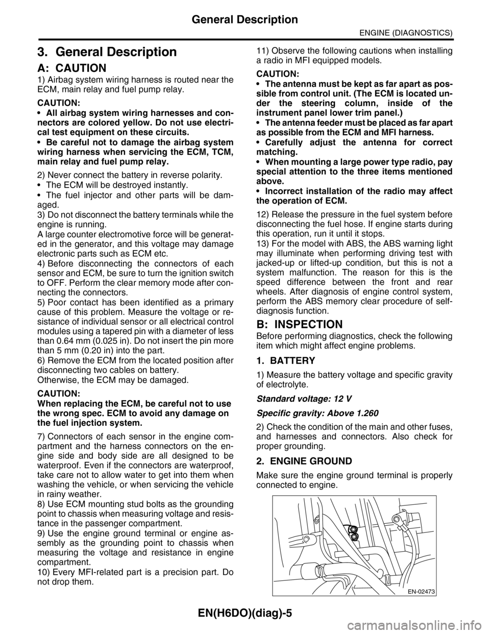
Make sure the engine ground terminal is properly
connected to engine.
EN-02473
Page 1199 of 2453
EN(H6DO)(diag)-38
Inspection Mode
ENGINE (DIAGNOSTICS)
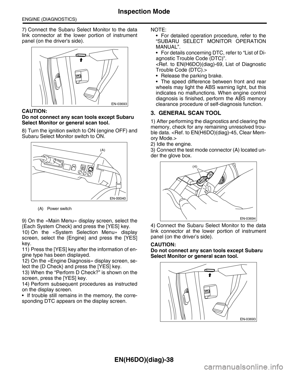
7) Connect the Subaru Select Monitor to the data
link connector at the lower portion of instrument
panel (on the driver's side).
CAUTION:
Do not connect any scan tools except Subaru
Select Monitor or general scan tool.
8) Turn the ignition switch to ON (engine OFF) and
Subaru Select Monitor switch to ON.
9) On the «Main Menu» display screen, select the
{Each System Check} and press the [YES] key.
10) On the «System Selection Menu» display
screen, select the {Engine} and press the [YES]
key.
11) Press the [YES] key after the information of en-
gine type has been displayed.
12) On the «Engine Diagnosis» display screen, se-
lect the {D Check} and press the [YES] key.
13) When the “Perform D Check?” is shown on the
screen, press the [YES] key.
14) Perform subsequent procedures as instructed
on the display screen.
•If trouble still remains in the memory, the corre-
sponding DTC appears on the display screen.
NOTE:
•For detailed operation procedure, refer to the
“SUBARU SELECT MONITOR OPERATION
MANUAL”.
•For details concerning DTC, refer to “List of Di-
agnostic Trouble Code (DTC)”.
•Release the parking brake.
•The speed difference between front and rear
wheels may light the ABS warning light, but this
indicates no malfunctions. When engine control
diagnosis is finished, perform the ABS memory
clearance procedure of self-diagnosis function.
3. GENERAL SCAN TOOL
1) After performing the diagnostics and clearing the
memory, check for any remaining unresolved trou-
ble data.
2) Idle the engine.
3) Connect the test mode connector (A) located un-
der the glove box.
4) Connect the Subaru Select Monitor to the data
link connector at the lower portion of instrument
panel (on the driver’s side).
CAUTION:
Do not connect any scan tools except Subaru
Select Monitor or general scan tool.
(A) Power switch
EN-03693
(A)
EN-00040
EN-03694
(4)
EN-03693
Page 1200 of 2453
EN(H6DO)(diag)-39
Inspection Mode
ENGINE (DIAGNOSTICS)
5) Start the engine.
NOTE:
Make sure the select lever is placed in “P” position
before starting.
6) Using the select lever, turn the “P” position
switch and the “N” position switch to ON.
7) Depress the brake pedal to turn brake switch
ON.
8) Keep the engine speed in 2,500 — 3,000 rpm
range for 40 seconds.
9) Shift the select lever in the “D” range and drive
the vehicle at 5 to 10 km/h (3 to 6 MPH).
NOTE:
•For AWD model, release the parking brake.
•The speed difference between front and rear
wheels may light the ABS warning light, but this in-
dicates no malfunctions. When engine control diag-
nosis is finished, perform the ABS memory
clearance procedure of self-diagnosis system.
10) Using the general scan tool, check DTC and
record the result(s).
NOTE:
•For detailed operation procedure, refer to the
general scan tool operation manual.
•For details concerning DTC, refer to “List of Diag-
nostic Trouble Code (DTC)”.
Page 1680 of 2453
GD(H6DO)-68
Diagnostic Trouble Code (DTC) Detecting Criteria
GENERAL DESCRIPTION
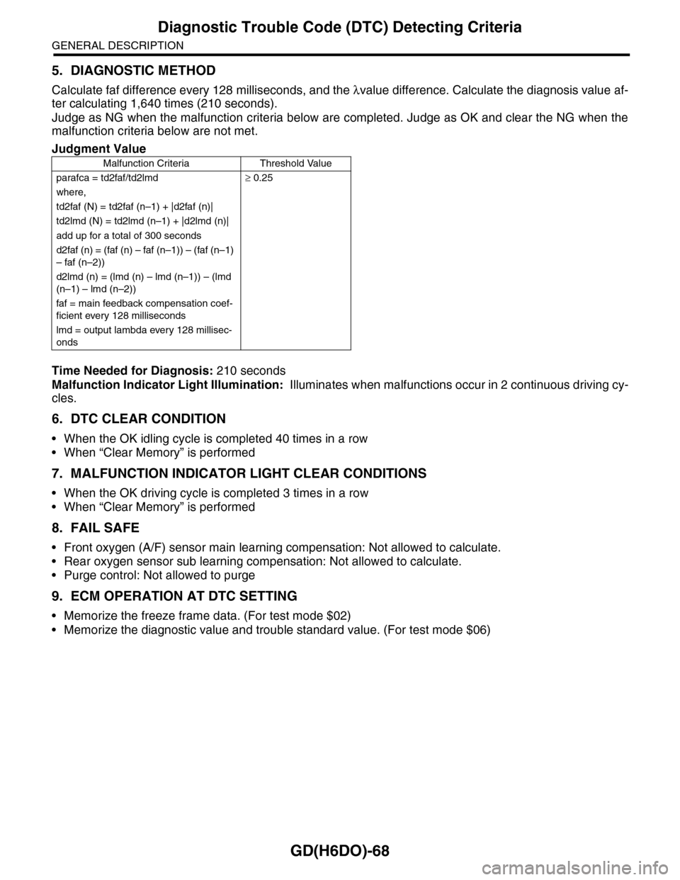
5. DIAGNOSTIC METHOD
Calculate faf difference every 128 milliseconds, and the λvalue difference. Calculate the diagnosis value af-
ter calculating 1,640 times (210 seconds).
Judge as NG when the malfunction criteria below are completed. Judge as OK and clear the NG when the
malfunction criteria below are not met.
Time Needed for Diagnosis: 210 seconds
Malfunction Indicator Light Illumination: Illuminates when malfunctions occur in 2 continuous driving cy-
cles.
6. DTC CLEAR CONDITION
•When the OK idling cycle is completed 40 times in a row
•When “Clear Memory” is performed
7. MALFUNCTION INDICATOR LIGHT CLEAR CONDITIONS
•When the OK driving cycle is completed 3 times in a row
•When “Clear Memory” is performed
8. FAIL SAFE
•Front oxygen (A/F) sensor main learning compensation: Not allowed to calculate.
•Rear oxygen sensor sub learning compensation: Not allowed to calculate.
•Purge control: Not allowed to purge
9. ECM OPERATION AT DTC SETTING
•Memorize the freeze frame data. (For test mode $02)
•Memorize the diagnostic value and trouble standard value. (For test mode $06)
Judgment Value
Malfunction Criteria Threshold Value
parafca = td2faf/td2lmd≥ 0.25
where,
td2faf (N) = td2faf (n–1) + |d2faf (n)|
td2lmd (N) = td2lmd (n–1) + |d2lmd (n)|
add up for a total of 300 seconds
d2faf (n) = (faf (n) – faf (n–1)) – (faf (n–1)
– faf (n–2))
d2lmd (n) = (lmd (n) – lmd (n–1)) – (lmd
(n–1) – lmd (n–2))
faf = main feedback compensation coef-
ficient every 128 milliseconds
lmd = output lambda every 128 millisec-
onds
Page 1734 of 2453
GD(H6DO)-122
Diagnostic Trouble Code (DTC) Detecting Criteria
GENERAL DESCRIPTION
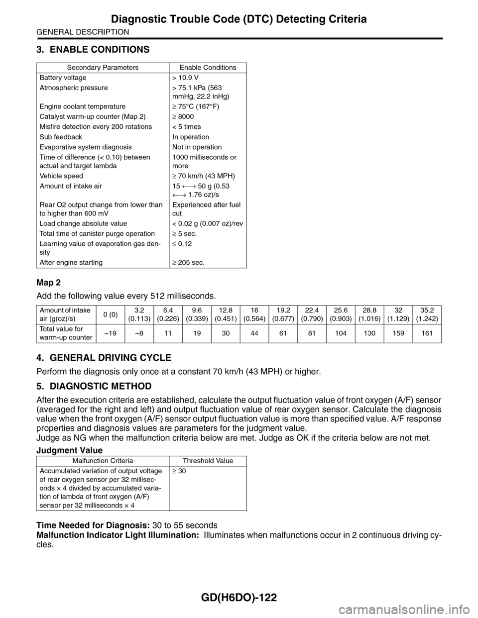
3. ENABLE CONDITIONS
Map 2
Add the following value every 512 milliseconds.
4. GENERAL DRIVING CYCLE
Perform the diagnosis only once at a constant 70 km/h (43 MPH) or higher.
5. DIAGNOSTIC METHOD
After the execution criteria are established, calculate the output fluctuation value of front oxygen (A/F) sensor
(averaged for the right and left) and output fluctuation value of rear oxygen sensor. Calculate the diagnosis
value when the front oxygen (A/F) sensor output fluctuation value is more than specified value. A/F response
properties and diagnosis values are parameters for the judgment value.
Judge as NG when the malfunction criteria below are met. Judge as OK if the criteria below are not met.
Time Needed for Diagnosis: 30 to 55 seconds
Malfunction Indicator Light Illumination: Illuminates when malfunctions occur in 2 continuous driving cy-
cles.
Secondary Parameters Enable Conditions
Battery voltage > 10.9 V
Atmospheric pressure > 75.1 kPa (563
mmHg, 22.2 inHg)
Engine coolant temperature≥ 75°C (167°F)
Catalyst warm-up counter (Map 2)≥ 8000
Misfire detection every 200 rotations < 5 times
Sub feedback In operation
Evaporative system diagnosis Not in operation
Time of difference (< 0.10) between
actual and target lambda
1000 milliseconds or
more
Ve h i c l e s p e e d≥ 70 km/h (43 MPH)
Amount of intake air 15 ←→ 50 g (0.53
←→ 1.76 oz)/s
Rear O2 output change from lower than
to higher than 600 mV
Experienced after fuel
cut
Load change absolute value < 0.02 g (0.007 oz)/rev
To t a l t i m e o f c a n i s t e r p u r g e o p e r a t i o n≥ 5 sec.
Learning value of evaporation gas den-
sity
≤ 0.12
After engine starting≥ 205 sec.
Amount of intake
air (g(oz)/s)0 (0)3.2
(0.113)
6.4
(0.226)
9.6
(0.339)
12.8
(0.451)
16
(0.564)
19.2
(0.677)
22.4
(0.790)
25.6
(0.903)
28.8
(1.016)
32
(1.129)
35.2
(1.242)
To t a l v a l u e f o r
warm-up counter–19 –8 11 19 30 44 61 81 104 130 159 161
Judgment Value
Malfunction Criteria Threshold Value
Accumulated variation of output voltage
of rear oxygen sensor per 32 millisec-
onds × 4 divided by accumulated varia-
tion of lambda of front oxygen (A/F)
sensor per 32 milliseconds × 4
≥ 30
Page 1917 of 2453
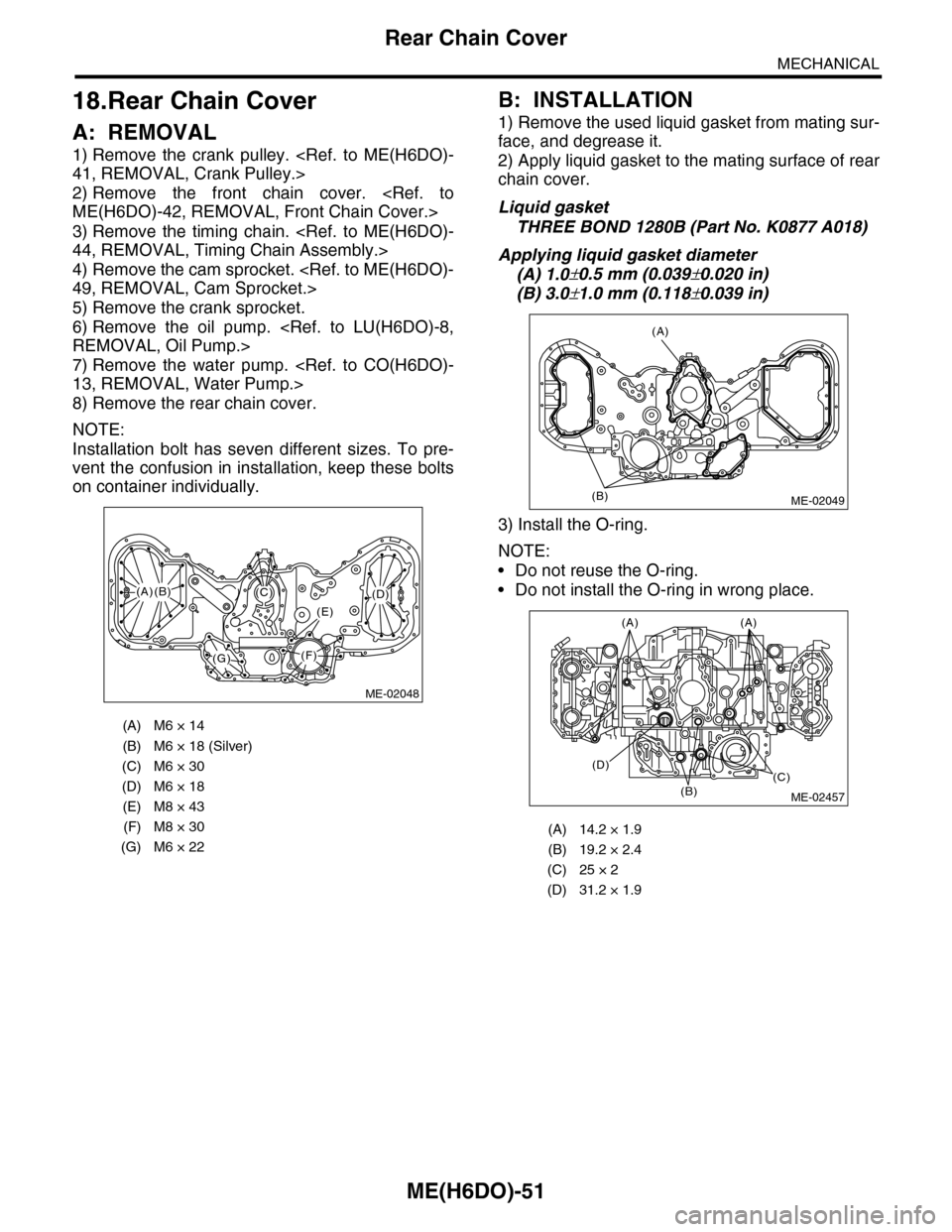
ME(H6DO)-51
Rear Chain Cover
MECHANICAL
18.Rear Chain Cover
A: REMOVAL
1) Remove the crank pulley.
2) Remove the front chain cover.
3) Remove the timing chain.
4) Remove the cam sprocket.
5) Remove the crank sprocket.
6) Remove the oil pump.
7) Remove the water pump.
8) Remove the rear chain cover.
NOTE:
Installation bolt has seven different sizes. To pre-
vent the confusion in installation, keep these bolts
on container individually.
B: INSTALLATION
1) Remove the used liquid gasket from mating sur-
face, and degrease it.
2) Apply liquid gasket to the mating surface of rear
chain cover.
Liquid gasket
THREE BOND 1280B (Part No. K0877 A018)
Applying liquid gasket diameter
(A) 1.0±0.5 mm (0.039±0.020 in)
(B) 3.0±1.0 mm (0.118±0.039 in)
3) Install the O-ring.
NOTE:
•Do not reuse the O-ring.
•Do not install the O-ring in wrong place.
(A) M6 × 14
(B) M6 × 18 (Silver)
(C) M6 × 30
(D) M6 × 18
(E) M8 × 43
(F) M8 × 30
(G) M6 × 22
ME-02048
(F)
(C)(D)
(E)
(G)
(A)(B)
(A) 14.2 × 1.9
(B) 19.2 × 2.4
(C) 25 × 2
(D) 31.2 × 1.9
(A)
(B)ME-02049
(B)
(D)(C)
(A)(A)
ME-02457
Page 1929 of 2453
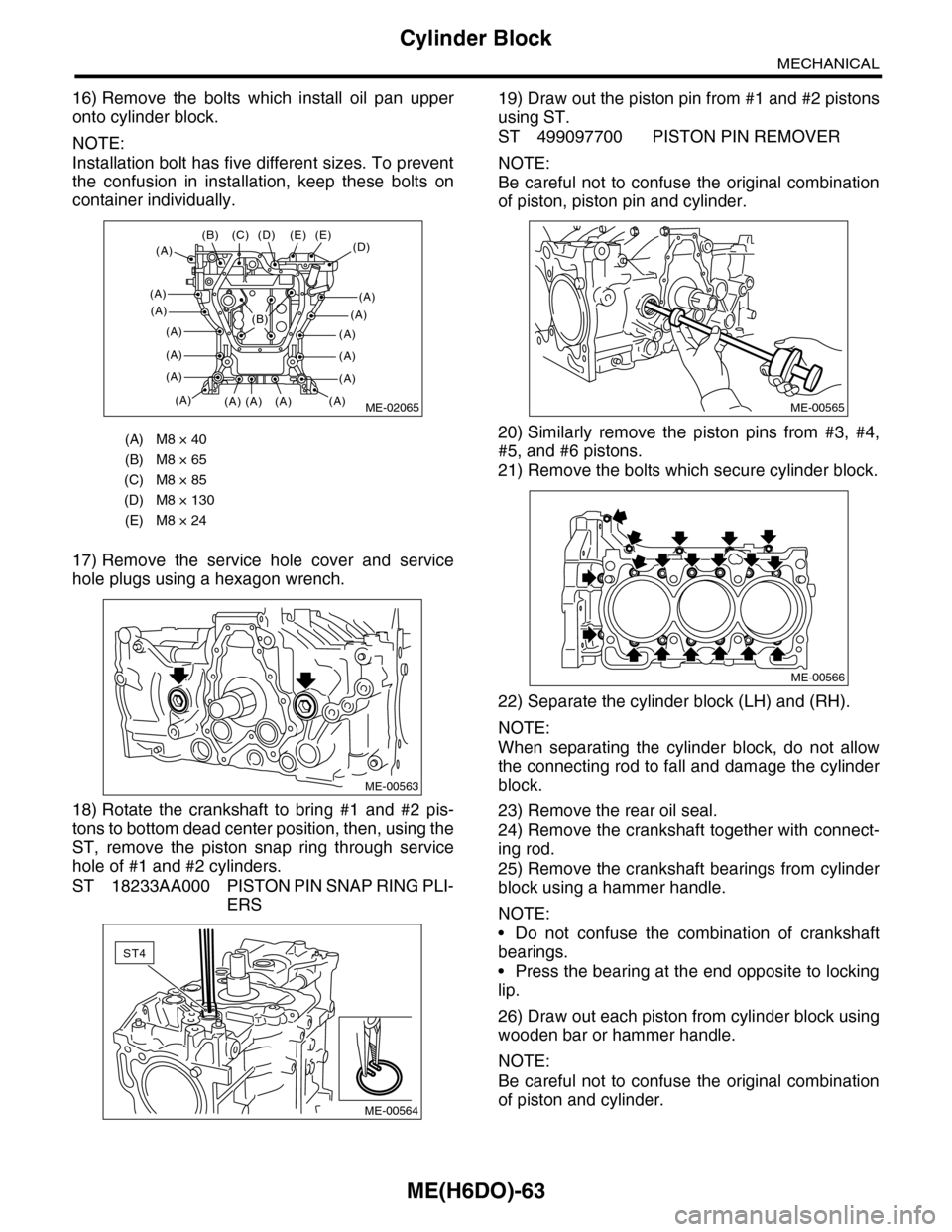
ME(H6DO)-63
Cylinder Block
MECHANICAL
16) Remove the bolts which install oil pan upper
onto cylinder block.
NOTE:
Installation bolt has five different sizes. To prevent
the confusion in installation, keep these bolts on
container individually.
17) Remove the service hole cover and service
hole plugs using a hexagon wrench.
18) Rotate the crankshaft to bring #1 and #2 pis-
tons to bottom dead center position, then, using the
ST, remove the piston snap ring through service
hole of #1 and #2 cylinders.
ST 18233AA000 PISTON PIN SNAP RING PLI-
ERS
19) Draw out the piston pin from #1 and #2 pistons
using ST.
ST 499097700 PISTON PIN REMOVER
NOTE:
Be careful not to confuse the original combination
of piston, piston pin and cylinder.
20) Similarly remove the piston pins from #3, #4,
#5, and #6 pistons.
21) Remove the bolts which secure cylinder block.
22) Separate the cylinder block (LH) and (RH).
NOTE:
When separating the cylinder block, do not allow
the connecting rod to fall and damage the cylinder
block.
23) Remove the rear oil seal.
24) Remove the crankshaft together with connect-
ing rod.
25) Remove the crankshaft bearings from cylinder
block using a hammer handle.
NOTE:
•Do not confuse the combination of crankshaft
bearings.
•Press the bearing at the end opposite to locking
lip.
26) Draw out each piston from cylinder block using
wooden bar or hammer handle.
NOTE:
Be careful not to confuse the original combination
of piston and cylinder.
(A) M8 × 40
(B) M8 × 65
(C) M8 × 85
(D) M8 × 130
(E) M8 × 24
ME-02065
(D)(E)
(A)
(A)
(A)
(A)
(A)
(A)
(A)
(E)
(A)(A)(A)
(C)(B)
(A)
(D)
(A)
(A)
(A)
(A)
(A)
(B)
ME-00563
ST4
ME-00564
ME-00565
ME-00566